Setup Manual
Page 2
Table of Contents Chapter 1: INTRODUCTION ...3 1.1 1.2 1.3 1.4 1.5 1.6 2.1 2.2 2.3 2.4 3.1 3.2 4.1 4.2 4.3 4.4 5.1 5.2 5.3 5.4 Before You Start ...3 Package Checklist ...3 Motherboard FeaturesS ...4 Rear Panel Connectors (for Ver 5.x) ...6 Rear Panel Connectors (for Ver 6.x)...6 Motherboard Layout...7 Installing Central Processing Unit (CPU) ...8 Fan Headers ...9 Installing System Memory ...10 Connectors and Slots ...11 How to Setup Jumpers ...13 Detail Settings ...13 Driver ...
Table of Contents Chapter 1: INTRODUCTION ...3 1.1 1.2 1.3 1.4 1.5 1.6 2.1 2.2 2.3 2.4 3.1 3.2 4.1 4.2 4.3 4.4 5.1 5.2 5.3 5.4 Before You Start ...3 Package Checklist ...3 Motherboard FeaturesS ...4 Rear Panel Connectors (for Ver 5.x) ...6 Rear Panel Connectors (for Ver 6.x)...6 Motherboard Layout...7 Installing Central Processing Unit (CPU) ...8 Fan Headers ...9 Installing System Memory ...10 Connectors and Slots ...11 How to Setup Jumpers ...13 Detail Settings ...13 Driver ...
Setup Manual
Page 3
... board. „ Do not leave any unfastened small parts inside the case after installation. Before you start installing the motherboard, please make sure you follow the instructions below: „ Prepare a dry and stable working environment with sufficient lighting....Cable X 1 (optional) USB 2.0 Cable X1 (optional) S/PDIF Cable X 1 (optional) Serial ATA Power Cable X 1 (optional) 3 P4M900-M4 CHAPTER 1: INTRODUCTION 1.1 BEFORE YOU START Thank you take the motherboard out from dangerous area, such as heat source, humid air and water. 1.2 PACKAGE CHECKLIST HDD Cable X 1 User's Manual X 1 Fully...
... board. „ Do not leave any unfastened small parts inside the case after installation. Before you start installing the motherboard, please make sure you follow the instructions below: „ Prepare a dry and stable working environment with sufficient lighting....Cable X 1 (optional) USB 2.0 Cable X1 (optional) S/PDIF Cable X 1 (optional) Serial ATA Power Cable X 1 (optional) 3 P4M900-M4 CHAPTER 1: INTRODUCTION 1.1 BEFORE YOU START Thank you take the motherboard out from dangerous area, such as heat source, humid air and water. 1.2 PACKAGE CHECKLIST HDD Cable X 1 User's Manual X 1 Fully...
Setup Manual
Page 4
... Controller ITE's "Smart Guardian" function DIMM S lots x 2 Supports DDR2 533 / 667 95W power consumption. 400 / 533 / 800 MHz VIA P4M900 VIA VT8237A Chrome9 HC 3D / 2D Graphics Max Shared Video Memory is recommended to use processors with 95W power consumption. SATA Version 1.0 specification compliant. ...*It is recommended to use processors with *It is 256 MB ITE 8718F Provides the most commonly used legacy Super I /O functionality. Motherboard Manual 1.3 MOTHERBOARD FEATURES Ver 5.x Socket 478 Socket 478 Ver 6.x Intel Pent ium 4 / Celeron D processor up to Intel Pent ium 4 / Celeron D ...
... Controller ITE's "Smart Guardian" function DIMM S lots x 2 Supports DDR2 533 / 667 95W power consumption. 400 / 533 / 800 MHz VIA P4M900 VIA VT8237A Chrome9 HC 3D / 2D Graphics Max Shared Video Memory is recommended to use processors with 95W power consumption. SATA Version 1.0 specification compliant. ...*It is recommended to use processors with *It is 256 MB ITE 8718F Provides the most commonly used legacy Super I /O functionality. Motherboard Manual 1.3 MOTHERBOARD FEATURES Ver 5.x Socket 478 Socket 478 Ver 6.x Intel Pent ium 4 / Celeron D processor up to Intel Pent ium 4 / Celeron D ...
Setup Manual
Page 6
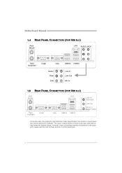
The input / output function of each audio jack listed above represents the default setting. Motherboard Manual 1.4 REAR PANEL CONNECTORS (FOR VER 5.X) LAN AUDIO JACK PS/2 Mouse PS/2 Keyboard COM1 VGA USBX2 USBX2 Center Rear Side Line In Line Out Mic ...
The input / output function of each audio jack listed above represents the default setting. Motherboard Manual 1.4 REAR PANEL CONNECTORS (FOR VER 5.X) LAN AUDIO JACK PS/2 Mouse PS/2 Keyboard COM1 VGA USBX2 USBX2 Center Rear Side Line In Line Out Mic ...
Setup Manual
Page 7
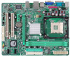
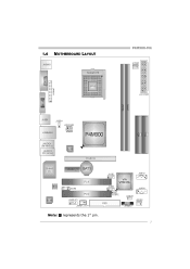
P4M900-M4 1.6 JKBMS1 MOTHERBOARD LAYOUT JCFAN1 PU Socket 478 M1 JCO CPU1 JPRNT1 JATXPWR1 DIMM1 JUSBV1 JATXPWR2 JUSB1 IDE1 JUSB2 JAUDIO1 (for Ver 5.x) JAUDIO2 (for Ver 6.x) LAN PCI-EX16 Super I/O PCI-EX1_1 BAT1 JSATA2 PCI1 BIOS JCDIN1 JUSB3 VIA VT8237A JSATA1 PCI2 Codec JAUDIOF1 JUSBV2 JCMOS1 JSFAN1 FDD1 JSPDIF_OUT1 JPANEL1 Note:
P4M900-M4 1.6 JKBMS1 MOTHERBOARD LAYOUT JCFAN1 PU Socket 478 M1 JCO CPU1 JPRNT1 JATXPWR1 DIMM1 JUSBV1 JATXPWR2 JUSB1 IDE1 JUSB2 JAUDIO1 (for Ver 5.x) JAUDIO2 (for Ver 6.x) LAN PCI-EX16 Super I/O PCI-EX1_1 BAT1 JSATA2 PCI1 BIOS JCDIN1 JUSB3 VIA VT8237A JSATA1 PCI2 Codec JAUDIOF1 JUSBV2 JCMOS1 JSFAN1 FDD1 JSPDIF_OUT1 JPANEL1 Note:
Setup Manual
Page 8
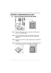
Connect the CPU FAN power cable to complete the installation. The CPU will fit only in the correct orientation. Step 3: Hold the CPU down firmly, and then close the lever to the JCFAN1. Motherboard Manual CHAPTER 2: HARDWARE INSTALLATION 2.1 INSTALLING CENTRAL PROCESSING UNIT (CPU) Step 1: Pull the lever sideways away from the socket and then raise the lever up to a 90-degree angle. The white dot/cut edge. Step 2: Look for the white dot/cut edge should point wards the lever pivot. Step 4: Put the CPU Fan on the CPU and buckle it. This completes the installation. 8
Connect the CPU FAN power cable to complete the installation. The CPU will fit only in the correct orientation. Step 3: Hold the CPU down firmly, and then close the lever to the JCFAN1. Motherboard Manual CHAPTER 2: HARDWARE INSTALLATION 2.1 INSTALLING CENTRAL PROCESSING UNIT (CPU) Step 1: Pull the lever sideways away from the socket and then raise the lever up to a 90-degree angle. The white dot/cut edge. Step 2: Look for the white dot/cut edge should point wards the lever pivot. Step 4: Put the CPU Fan on the CPU and buckle it. This completes the installation. 8

Setup Manual
Page 10
B. Align a DIMM on the slot such that the notch on the DIMM matches the break on the Slot. 2. Unlock a DIMM slot by pressing the retaining clips outward. Insert the DIMM vertically and firmly into the slot until the retaining chip snap back in place and the DIMM is 4GB. 10 DIMM1 DIMM2 Motherboard Manual 2.3 INSTALLING SYSTEM MEMORY A. Memory Capacity DIMM Socket Location DIMM1 DIMM2 DDR Module 256MB/512MB/1GB/2GB 256MB/512MB/1GB/2GB Total Memory Size Max is properly seated. Memory Modules 1.
B. Align a DIMM on the slot such that the notch on the DIMM matches the break on the Slot. 2. Unlock a DIMM slot by pressing the retaining clips outward. Insert the DIMM vertically and firmly into the slot until the retaining chip snap back in place and the DIMM is 4GB. 10 DIMM1 DIMM2 Motherboard Manual 2.3 INSTALLING SYSTEM MEMORY A. Memory Capacity DIMM Socket Location DIMM1 DIMM2 DDR Module 256MB/512MB/1GB/2GB 256MB/512MB/1GB/2GB Total Memory Size Max is properly seated. Memory Modules 1.

Setup Manual
Page 11
... IDE1/IDE2: Hard Disk Connectors The motherboard has a 32-bit Enhanced PCI IDE Controller that supports 360K, 720K, 1.2M, 1.44M and 2.88M floppy disk types. The first hard drive should always be connected to four hard disk drives. P4M900-M4 2.4 CONNECTORS AND SLOTS FDD1: Floppy Disk... Connector The motherboard provides a standard floppy disk connector that provides PIO Mode 0~4, Bus Master, and Ultra DMA 33/66/100/133...
... IDE1/IDE2: Hard Disk Connectors The motherboard has a 32-bit Enhanced PCI IDE Controller that supports 360K, 720K, 1.2M, 1.44M and 2.88M floppy disk types. The first hard drive should always be connected to four hard disk drives. P4M900-M4 2.4 CONNECTORS AND SLOTS FDD1: Floppy Disk... Connector The motherboard provides a standard floppy disk connector that provides PIO Mode 0~4, Bus Master, and Ultra DMA 33/66/100/133...

Setup Manual
Page 12
... bit-rate of 4GB/s simultaneously per direction; 500MB/s in total. PCI-Express 1.0a compliant. PCI-EX16 PCI-EX1_1 PCI1~PCI2: Peripheral Component Interconnect Slots This motherboard is designated as 32 bits. Motherboard Manual PCI-EX16: PCI-Express x16 Slot PCI-Express 1.0a compliant.
... bit-rate of 4GB/s simultaneously per direction; 500MB/s in total. PCI-Express 1.0a compliant. PCI-EX16 PCI-EX1_1 PCI1~PCI2: Peripheral Component Interconnect Slots This motherboard is designated as 32 bits. Motherboard Manual PCI-EX16: PCI-Express x16 Slot PCI-Express 1.0a compliant.
Setup Manual
Page 14
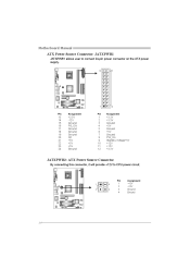
Motherboard Manual ATX Power Source Connector: JATXPWR1 JATXPWR1 allows user to connect 24-pin power connector on the ATX power supply. 12 24 1 13 Pin Assignment Pin Assignment 13 14 15 16 17 18 19 20 21 22 23 24 +3.3V -12V Ground PS_ON Ground Ground Ground NC +5V +5V +5V Ground 1 2 3 4 5 6 7 8 9 10 11 12 +3.3V +3.3V Ground +5V Ground +5V Ground PW_OK Standby Voltage+5V +12V +12V +3.3V JATXPWR2: ATX Power Source Connector By connecting this connector, it will provide +12V to CPU power circuit. 1 2 4 3 Pin 1 2 3 4 Assignment +12V +12V Ground Ground 14
Motherboard Manual ATX Power Source Connector: JATXPWR1 JATXPWR1 allows user to connect 24-pin power connector on the ATX power supply. 12 24 1 13 Pin Assignment Pin Assignment 13 14 15 16 17 18 19 20 21 22 23 24 +3.3V -12V Ground PS_ON Ground Ground Ground NC +5V +5V +5V Ground 1 2 3 4 5 6 7 8 9 10 11 12 +3.3V +3.3V Ground +5V Ground +5V Ground PW_OK Standby Voltage+5V +12V +12V +3.3V JATXPWR2: ATX Power Source Connector By connecting this connector, it will provide +12V to CPU power circuit. 1 2 4 3 Pin 1 2 3 4 Assignment +12V +12V Ground Ground 14

Setup Manual
Page 16
Motherboard Manual JAUDIOF1: Front Panel Audio Header This header allows user to connect the audio source from the variaty devices, like CD-ROM, DVD-ROM, PCI ...
Motherboard Manual JAUDIOF1: Front Panel Audio Header This header allows user to connect the audio source from the variaty devices, like CD-ROM, DVD-ROM, PCI ...

Setup Manual
Page 17
...4 1 Pin 1 2 3 4 5 6 7 Assignment Ground TX+ TXGround RXRX+ Ground 1 JSATA1 4 7 17 P4M900-M4 JCMOS1: Clear CMOS Header By placing the jumper on the AC. Remove AC power line. Set the jumper to avoid damaging the motherboard. 1 3 Pin 1-2 Close: Normal Operation (default). 1 3 1 3 Pin 2-3 Close: Clear CMOS data. &#...8251; Clear CMOS Procedures: 1. 2. 3. 4. 5. 6. JSATA1~JSATA2: Serial ATA Connectors The motherboard has a PCI to SATA Controller with 2 channels SATA interface, it allows user to restore the BIOS safe setting and the CMOS data, ...
...4 1 Pin 1 2 3 4 5 6 7 Assignment Ground TX+ TXGround RXRX+ Ground 1 JSATA1 4 7 17 P4M900-M4 JCMOS1: Clear CMOS Header By placing the jumper on the AC. Remove AC power line. Set the jumper to avoid damaging the motherboard. 1 3 Pin 1-2 Close: Normal Operation (default). 1 3 1 3 Pin 2-3 Close: Clear CMOS data. &#...8251; Clear CMOS Procedures: 1. 2. 3. 4. 5. 6. JSATA1~JSATA2: Serial ATA Connectors The motherboard has a PCI to SATA Controller with 2 channels SATA interface, it allows user to restore the BIOS safe setting and the CMOS data, ...
Setup Manual
Page 18
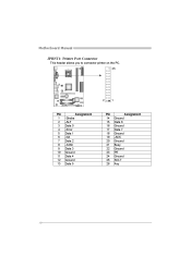
Motherboard Manual JPRNT1: Printer Port Connector This header allows you to connector printer on the PC. 25 2 1 Pin 1 2 3 4 5 6 7 8 9 10 11 12 13 Assignment -Strobe -ALF Data 0 -Error Data 1 -Init Data 2 -Scltin Data 3 Ground Data 4 Ground Data 5 Pin 14 15 16 17 18 19 20 21 22 23 24 25 26 Assignment Ground Data 6 Ground Data 7 Ground -ACK Ground Busy Ground PE Ground SCLT Key 18
Motherboard Manual JPRNT1: Printer Port Connector This header allows you to connector printer on the PC. 25 2 1 Pin 1 2 3 4 5 6 7 8 9 10 11 12 13 Assignment -Strobe -ALF Data 0 -Error Data 1 -Init Data 2 -Scltin Data 3 Ground Data 4 Ground Data 5 Pin 14 15 16 17 18 19 20 21 22 23 24 25 26 Assignment Ground Data 6 Ground Data 7 Ground -ACK Ground Busy Ground PE Ground SCLT Key 18
Setup Manual
Page 19
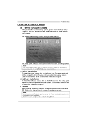
... Click on the Driver icon. Driver Installation To install the driver, please click on the Manual icon to launch the installation program. B. P4M900-M4 CHAPTER 4: USEFUL HELP 4.1 DRIVER INSTALLATION NOTE After you installed your operating system, please insert the Fully Setup Driver CD into your optical ...the file SETUP.EXE under your optical drive and install the driver for available manual. The setup guide will auto detect your motherboard and operating system. Note: You will list the compatible driver for your system, click on each device driver to browse for ...
... Click on the Driver icon. Driver Installation To install the driver, please click on the Manual icon to launch the installation program. B. P4M900-M4 CHAPTER 4: USEFUL HELP 4.1 DRIVER INSTALLATION NOTE After you installed your operating system, please insert the Fully Setup Driver CD into your optical ...the file SETUP.EXE under your optical drive and install the driver for available manual. The setup guide will auto detect your motherboard and operating system. Note: You will list the compatible driver for your system, click on each device driver to browse for ...
Setup Manual
Page 20
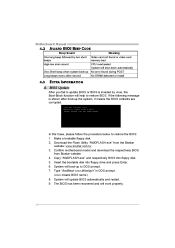
... procedure below to restore BIOS. Make a bootable floppy disk. 2. Type "Awdflash xxxx.bf/sn/py/r" in DOS prompt. (xxxx means BIOS name.) 8. Motherboard Manual 4.2 AWARD BIOS BEEP CODE Beep Sound Meaning Video card not found or video card memory bad CPU overheated System will shut down automatically No... following message is invaded by virus, the Boot-Block function will boot-up the system, it means the BIOS contents are corrupted. Confirm motherboard model and download the respectively BIOS from the Biostar website: www.biostar.com.tw 3. System will help to restore the BIOS: 1.
... procedure below to restore BIOS. Make a bootable floppy disk. 2. Type "Awdflash xxxx.bf/sn/py/r" in DOS prompt. (xxxx means BIOS name.) 8. Motherboard Manual 4.2 AWARD BIOS BEEP CODE Beep Sound Meaning Video card not found or video card memory bad CPU overheated System will shut down automatically No... following message is invaded by virus, the Boot-Block function will boot-up the system, it means the BIOS contents are corrupted. Confirm motherboard model and download the respectively BIOS from the Biostar website: www.biostar.com.tw 3. System will help to restore the BIOS: 1.

Setup Manual
Page 21
... CPU fan speed is placed evenly with the CPU speed. Plug in the power cord and boot up the system. Power on system for seconds. 3. P4M900-M4 B. The CPU cooler surface is fulfilling with the CPU surface. 2. Wait for seconds. 2. Remove the power cord from power supply for seconds. 3...., please follow steps below to avoid a damage of the CPU, and the system may not power on again. CPU fan is over heated, the motherboard will shutdown automatically to relief the CPU protection function. 1. Clear the CMOS data. (See "Close CMOS Header: JCMOS1" section) 2. Or you can...
... CPU fan speed is placed evenly with the CPU speed. Plug in the power cord and boot up the system. Power on system for seconds. 3. P4M900-M4 B. The CPU cooler surface is fulfilling with the CPU surface. 2. Wait for seconds. 2. Remove the power cord from power supply for seconds. 3...., please follow steps below to avoid a damage of the CPU, and the system may not power on again. CPU fan is over heated, the motherboard will shutdown automatically to relief the CPU protection function. 1. Clear the CMOS data. (See "Close CMOS Header: JCMOS1" section) 2. Or you can...

Setup Manual
Page 22
... system at any time. Backing up data and applications Hard disk can be booted from hard disk 2. Run SETUP program and select correct drive types. Motherboard Manual 4.4 1. System does not boot from optical drive. 1. check the drive type in . System only boots from hard disk 1. All hard disks are lit, the...
... system at any time. Backing up data and applications Hard disk can be booted from hard disk 2. Run SETUP program and select correct drive types. Motherboard Manual 4.4 1. System does not boot from optical drive. 1. check the drive type in . System only boots from hard disk 1. All hard disks are lit, the...
Setup Manual
Page 24
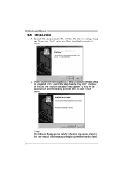
Please click "Next" button and follow the default procedure to your motherboard on hand. 24 When you click "Finish" button. If the "Launch the WarpSpeeder Tray Utility" checkbox is completed. Usage: The following dialog in this user ... only for reference, the screen printed in setup procedure, it means setup is checked, the Tray Icon utility and [WarpSpeeder™] utility will pop up. Motherboard Manual 5.3 INSTALLATION 1.
Please click "Next" button and follow the default procedure to your motherboard on hand. 24 When you click "Finish" button. If the "Launch the WarpSpeeder Tray Utility" checkbox is completed. Usage: The following dialog in this user ... only for reference, the screen printed in setup procedure, it means setup is checked, the Tray Icon utility and [WarpSpeeder™] utility will pop up. Motherboard Manual 5.3 INSTALLATION 1.
Setup Manual
Page 26
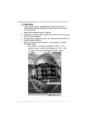
Motherboard Manual 2. With a user-friendly Status Animation, it can represent 3 overclock percentage stages: Man walking→overclock percentage from 100% ~ 110 % Panther running→overclock percentage ...
Motherboard Manual 2. With a user-friendly Status Animation, it can represent 3 overclock percentage stages: Man walking→overclock percentage from 100% ~ 110 % Panther running→overclock percentage ...
Setup Manual
Page 28
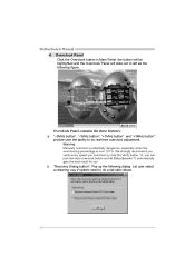
... the these features: a. b. "Recovery Dialog button": Pop up the following figure. Warning: Manually overclock is potentially dangerous, especially when the overclocking percentage is over 110 %. Motherboard Manual 4. We strongly recommend you verify every speed you .
... the these features: a. b. "Recovery Dialog button": Pop up the following figure. Warning: Manually overclock is potentially dangerous, especially when the overclocking percentage is over 110 %. Motherboard Manual 4. We strongly recommend you verify every speed you .

