Setup Manual
Page 2
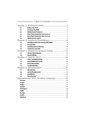
... Unit (CPU) ...8 Fan Headers ...9 Installing System Memory ...10 Connectors and Slots ...11 How to Setup Jumpers ...13 Detail Settings ...13 Driver Installation Note...19 Award BIOS Beep Code ...20 Extra Information...20 Troubleshooting ...22 Introduction ...23 System Requirement ...23 Installation ...24 WarpSpeeder™ ...25 Chapter 2: Hardware Installation ...8 Chapter 3: Headers & Jumpers Setup...
... Unit (CPU) ...8 Fan Headers ...9 Installing System Memory ...10 Connectors and Slots ...11 How to Setup Jumpers ...13 Detail Settings ...13 Driver Installation Note...19 Award BIOS Beep Code ...20 Extra Information...20 Troubleshooting ...22 Introduction ...23 System Requirement ...23 Installation ...24 WarpSpeeder™ ...25 Chapter 2: Hardware Installation ...8 Chapter 3: Headers & Jumpers Setup...
Setup Manual
Page 7
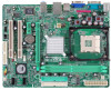
P4M900-M4 1.6 JKBMS1 MOTHERBOARD LAYOUT JCFAN1 PU Socket 478 M1 JCO CPU1 JPRNT1 JATXPWR1 DIMM1 JUSBV1 JATXPWR2 JUSB1 IDE1 JUSB2 JAUDIO1 (for Ver 5.x) JAUDIO2 (for Ver 6.x) LAN PCI-EX16 Super I/O PCI-EX1_1 BAT1 JSATA2 PCI1 BIOS JCDIN1 JUSB3 VIA VT8237A JSATA1 PCI2 Codec JAUDIOF1 JUSBV2 JCMOS1 JSFAN1 FDD1 JSPDIF_OUT1 JPANEL1 Note:
P4M900-M4 1.6 JKBMS1 MOTHERBOARD LAYOUT JCFAN1 PU Socket 478 M1 JCO CPU1 JPRNT1 JATXPWR1 DIMM1 JUSBV1 JATXPWR2 JUSB1 IDE1 JUSB2 JAUDIO1 (for Ver 5.x) JAUDIO2 (for Ver 6.x) LAN PCI-EX16 Super I/O PCI-EX1_1 BAT1 JSATA2 PCI1 BIOS JCDIN1 JUSB3 VIA VT8237A JSATA1 PCI2 Codec JAUDIOF1 JUSBV2 JCMOS1 JSFAN1 FDD1 JSPDIF_OUT1 JPANEL1 Note:

Setup Manual
Page 17
P4M900-M4 JCMOS1: Clear CMOS Header By placing the jumper on the AC. Set the jumper to "Pin 1-2 close ". Wait for five seconds. JSATA1~JSATA2: Serial ATA Connectors The motherboard has a PCI to SATA Controller with 2 channels SATA interface, it allows user to restore the BIOS safe setting and the CMOS data, please carefully...
P4M900-M4 JCMOS1: Clear CMOS Header By placing the jumper on the AC. Set the jumper to "Pin 1-2 close ". Wait for five seconds. JSATA1~JSATA2: Serial ATA Connectors The motherboard has a PCI to SATA Controller with 2 channels SATA interface, it allows user to restore the BIOS safe setting and the CMOS data, please carefully...
Setup Manual
Page 20
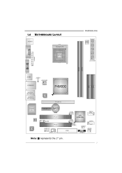
.../sn/py/r" in DOS prompt. (xxxx means BIOS name.) 8. Download the Flash Utility "AWDFLASH.exe" from Biostar website. 4. Confirm motherboard model and download the respectively BIOS from the Biostar website: www.biostar.com.tw 3. Insert the bootable disk into floppy disk. 5. Make a bootable floppy disk. 2. Motherboard Manual 4.2 AWARD BIOS BEEP CODE Beep Sound Meaning Video card...
.../sn/py/r" in DOS prompt. (xxxx means BIOS name.) 8. Download the Flash Utility "AWDFLASH.exe" from Biostar website. 4. Confirm motherboard model and download the respectively BIOS from the Biostar website: www.biostar.com.tw 3. Insert the bootable disk into floppy disk. 5. Make a bootable floppy disk. 2. Motherboard Manual 4.2 AWARD BIOS BEEP CODE Beep Sound Meaning Video card...
Setup Manual
Page 23
... to power up CPU core voltage and Memory voltage. If you use Windows XP, you can get detail descriptions about BIOS model and chipsets. The cool Hardware Monitor smartly indicates the temperatures, voltage and CPU fan speed as well as the...Windows 98 SE, Windows Me, Windows 2000, Windows XP DirectX: DirectX 8.1 or above. (The Windows XP operating system includes DirectX 8.1. P4M900-M4 CHAPTER 5: WARPSPEEDER™ 5.1 INTRODUCTION [WarpSpeeder™], a new powerful control utility, features three user-friendly functions including Overclock Manager, Overvoltage Manager, and...
... to power up CPU core voltage and Memory voltage. If you use Windows XP, you can get detail descriptions about BIOS model and chipsets. The cool Hardware Monitor smartly indicates the temperatures, voltage and CPU fan speed as well as the...Windows 98 SE, Windows Me, Windows 2000, Windows XP DirectX: DirectX 8.1 or above. (The Windows XP operating system includes DirectX 8.1. P4M900-M4 CHAPTER 5: WARPSPEEDER™ 5.1 INTRODUCTION [WarpSpeeder™], a new powerful control utility, features three user-friendly functions including Overclock Manager, Overvoltage Manager, and...
Setup Manual
Page 30
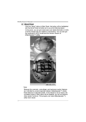
... up as the following figure. About Panel Click the "about" button in hints of [WarpSpeeder™] utility. In this panel, you can get the mainboard's BIOS model and the Version number of all the chipset that are controlled by several separate chipset, [WarpSpeeder™] divide these features to overclocking.
... up as the following figure. About Panel Click the "about" button in hints of [WarpSpeeder™] utility. In this panel, you can get the mainboard's BIOS model and the Version number of all the chipset that are controlled by several separate chipset, [WarpSpeeder™] divide these features to overclocking.

Bios Setup
Page 1
P4M900-M4 BIOS Setup BIOS Setup 1 1 Main Menu 3 2 Standard CMOS Features 7 3Advanced BIOS Features 9 4 Advanced Chipset Features 17 5 Integrated Peripherals 21 6 Power Management Setup 27 7 PnP/PCI Configurations 32 8 PC Health Status 35 9 Performance Booster Zone 37 i
P4M900-M4 BIOS Setup BIOS Setup 1 1 Main Menu 3 2 Standard CMOS Features 7 3Advanced BIOS Features 9 4 Advanced Chipset Features 17 5 Integrated Peripherals 21 6 Power Management Setup 27 7 PnP/PCI Configurations 32 8 PC Health Status 35 9 Performance Booster Zone 37 i
Bios Setup
Page 2
P4M900-M4 BIOS Setup Introduction The purpose of this manual will to guide you through the options and settings in BIOS Setup. The rest of this manual is turned off. APM Support This PHEONIX-AWARD BIOS supports Version 1.1&1.2 of CMOS RAM is supplied by this motherboard. Power to the hard ...information when the power is to CMOS RAM. Power management features are also included in the Pheonix-Award™ BIOS Setup program on this PHEONIX-AWARD BIOS. 1 BIOS activates at the first stage of the input and output devices such as virus and password protection or chipset ...
P4M900-M4 BIOS Setup Introduction The purpose of this manual will to guide you through the options and settings in BIOS Setup. The rest of this manual is turned off. APM Support This PHEONIX-AWARD BIOS supports Version 1.1&1.2 of CMOS RAM is supplied by this motherboard. Power to the hard ...information when the power is to CMOS RAM. Power management features are also included in the Pheonix-Award™ BIOS Setup program on this PHEONIX-AWARD BIOS. 1 BIOS activates at the first stage of the input and output devices such as virus and password protection or chipset ...
Bios Setup
Page 3
...ACPI). Keystroke Up arrow Down arrow Left arrow Right arrow Move Enter PgUp key PgDn key + Key - Supported CPUs This PHEONIX-AWARD BIOS supports the Intel CPU. DRAM Support DDR SDRAM (Double Data Rate Synchronous DRAM) is supported. Using Setup Use the arrow keys to ...to the item on the left (menu bar) Move to navigate in the ACPI specification, developed by using the keyboard. P4M900-M4 ACPI Support Pheonix-Award ACPI BIOS support Version 1.0b of the Intel PCI (Peripheral Component Interconnect) local bus specification. The following table provides more detail ...
...ACPI). Keystroke Up arrow Down arrow Left arrow Right arrow Move Enter PgUp key PgDn key + Key - Supported CPUs This PHEONIX-AWARD BIOS supports the Intel CPU. DRAM Support DDR SDRAM (Double Data Rate Synchronous DRAM) is supported. Using Setup Use the arrow keys to ...to the item on the left (menu bar) Move to navigate in the ACPI specification, developed by using the keyboard. P4M900-M4 ACPI Support Pheonix-Award ACPI BIOS support Version 1.0b of the Intel PCI (Peripheral Component Interconnect) local bus specification. The following table provides more detail ...
Bios Setup
Page 4
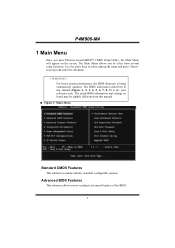
... you to select from this manual (Figure 1, 2, 3, 4, 5, 6, 7, 8, 9) is being continuously updated. The BIOS information described in this manual. „ Figure 1: Main Menu Standard CMOS Features This submenu contains industry standard configurable options. P4M900-M4 1 Main Menu Once you enter Pheonix-Award BIOS™ CMOS Setup Utility, the Main Menu will appear on board may...
... you to select from this manual (Figure 1, 2, 3, 4, 5, 6, 7, 8, 9) is being continuously updated. The BIOS information described in this manual. „ Figure 1: Main Menu Standard CMOS Features This submenu contains industry standard configurable options. P4M900-M4 1 Main Menu Once you enter Pheonix-Award BIOS™ CMOS Setup Utility, the Main Menu will appear on board may...
Bios Setup
Page 5
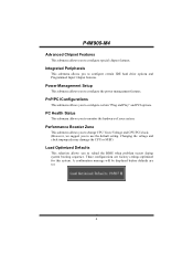
... certain "Plug and Play" and PCI options. These configurations are set. 4 PnP/PCI Configurations This submenu allows you to reload the BIOS when problem occurs during system booting sequence. P4M900-M4 Advanced Chipset Features This submenu allows you to configure the power management features. Power Management Setup This submenu allows you to configure...
... certain "Plug and Play" and PCI options. These configurations are set. 4 PnP/PCI Configurations This submenu allows you to reload the BIOS when problem occurs during system booting sequence. P4M900-M4 Advanced Chipset Features This submenu allows you to configure the power management features. Power Management Setup This submenu allows you to configure...

Bios Setup
Page 7
P4M900-M4 Upgrade BIOS This submenu allows you to upgrade bios. 6
P4M900-M4 Upgrade BIOS This submenu allows you to upgrade bios. 6

Bios Setup
Page 9
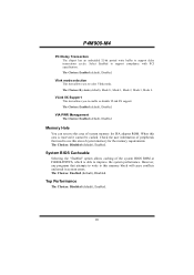
Select the type of detailed options. Select the situation in the system. 8 Displays the total memory available in which you want the BIOS to enter the sub menu of detailed options. P4M900-M4 Item IDE Channel 1 Master IDE Channel 1 Slave Drive A Drive B Halt On Base Memory Extended Memory Total Memory Options Options are in...
Select the type of detailed options. Select the situation in the system. 8 Displays the total memory available in which you want the BIOS to enter the sub menu of detailed options. P4M900-M4 Item IDE Channel 1 Master IDE Channel 1 Slave Drive A Drive B Halt On Base Memory Extended Memory Total Memory Options Options are in...

Bios Setup
Page 11
First/Second/Third Boot Device The BIOS will try to load the operating system from other device when it failed to swap logical drive assignments. The Choices: Disabled (default), Enabled. 10 You ... Disk, CDROM, ZIP100, USB-FDD, USB-ZIP, USB-CDROM, LAN, Disabled. Boot Other Device When enabled, BIOS will attempt to arrange the Hard Disk boot sequence automatically. Master, Sec. P4M900-M4 Hard Disk Boot Priority The BIOS will attempt to load the operating system in Cards. The Choices: Enabled (default), Disabled Swap Floppy Drive...
First/Second/Third Boot Device The BIOS will try to load the operating system from other device when it failed to swap logical drive assignments. The Choices: Disabled (default), Enabled. 10 You ... Disk, CDROM, ZIP100, USB-FDD, USB-ZIP, USB-CDROM, LAN, Disabled. Boot Other Device When enabled, BIOS will attempt to arrange the Hard Disk boot sequence automatically. Master, Sec. P4M900-M4 Hard Disk Boot Priority The BIOS will attempt to load the operating system in Cards. The Choices: Enabled (default), Disabled Swap Floppy Drive...

Bios Setup
Page 12
Shadow Setup This item allows you to setup cache & shadow setup. „ Figure 3.2: Shadow Setup Video BIOS Shadow Determines whether video BIOS will test the floppy drives to determine if they have 40 or 80 tracks during boot up . Disabled Optional ROM is enabled. Enabled (default) Optional ROM is disabled. 11 The Choices: Enabled (default), Disabled. P4M900-M4 Boot Up Floppy Seek When enabled, System will be copied to RAM for faster execution or not. Disabling this option reduces the time it takes to boot-up .
Shadow Setup This item allows you to setup cache & shadow setup. „ Figure 3.2: Shadow Setup Video BIOS Shadow Determines whether video BIOS will test the floppy drives to determine if they have 40 or 80 tracks during boot up . Disabled Optional ROM is enabled. Enabled (default) Optional ROM is disabled. 11 The Choices: Enabled (default), Disabled. P4M900-M4 Boot Up Floppy Seek When enabled, System will be copied to RAM for faster execution or not. Disabling this option reduces the time it takes to boot-up .

Bios Setup
Page 15
... attempt is id le. The Choices: Enabled (default), Disabled. Virus Warning This option allows you to the boot sector, BIOS will display a warning message on the screen and sound an alarm beep. P4M900-M4 Limit CPUID MaxVal Set Limit CPUID MaxVal to protect the IDE Hard Disk boot sector. The Choices: Disabled (default...
... attempt is id le. The Choices: Enabled (default), Disabled. Virus Warning This option allows you to the boot sector, BIOS will display a warning message on the screen and sound an alarm beep. P4M900-M4 Limit CPUID MaxVal Set Limit CPUID MaxVal to protect the IDE Hard Disk boot sector. The Choices: Disabled (default...
Bios Setup
Page 17
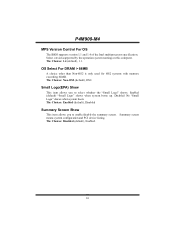
..." shows when system boots The Choices: Enabled (default), Disabled Summary Screen Show This item allows you to enable/disable the summary screen. P4M900-M4 MPS Version Control For OS The BIOS supports version 1.1 and 1.4 of the Intel multiprocessor specification. Select version supported by the operation system running on this computer. OS Select For...
..." shows when system boots The Choices: Enabled (default), Disabled Summary Screen Show This item allows you to enable/disable the summary screen. P4M900-M4 MPS Version Control For OS The BIOS supports version 1.1 and 1.4 of the Intel multiprocessor specification. Select version supported by the operation system running on this computer. OS Select For...
Bios Setup
Page 21
... F0000h-FFFFFh, which is reserved it cannot be cached. System BIOS Cacheable Selecting the "Enabled" option allows caching of peripherals that attempts to write to improve the system performance. However, any programs that need to support compliance with PCI specification. P4M900-M4 PCI Delay Transaction The chipset has an embedded 32-bit posted...
... F0000h-FFFFFh, which is reserved it cannot be cached. System BIOS Cacheable Selecting the "Enabled" option allows caching of peripherals that attempts to write to improve the system performance. However, any programs that need to support compliance with PCI specification. P4M900-M4 PCI Delay Transaction The chipset has an embedded 32-bit posted...
Bios Setup
Page 24
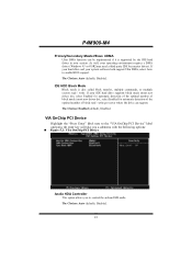
P4M900-M4 Primary/Secondary Master/Slave UDMA Ultra DMA function can be implemented if it is also called block transfer, multiple commands, or multiple sectors read / write ... enter key will take you a submenu with the following options: „ Figure 5.2: VIA OnChip PCI Device Azalia HDA Controller This option allows you to enable BIOS support. If your system software both support Ultra DMA, select Auto to control the onboard HD audio. As well, your system. IDE HDD Block Mode...
P4M900-M4 Primary/Secondary Master/Slave UDMA Ultra DMA function can be implemented if it is also called block transfer, multiple commands, or multiple sectors read / write ... enter key will take you a submenu with the following options: „ Figure 5.2: VIA OnChip PCI Device Azalia HDA Controller This option allows you to enable BIOS support. If your system software both support Ultra DMA, select Auto to control the onboard HD audio. As well, your system. IDE HDD Block Mode...

Bios Setup
Page 30
... MODEM use. Run VGABIOS if S3 Resume Choosing Enabled will restore the system to initialize the card. Former-Sts will make BIOS run VGA BIOS to cut off the vertical and horizontal synchronization ports and write blanks to the video buffer. The system resume time is shortened...system wakes up from S3 state. The Choices: Auto (default), Yes, No. Blank Screen This option only writes blanks to the video buffer. P4M900-M4 Video Off Method This option determines the manner when the monitor goes blank. V/H SYNC+Blank (default) This selection will reboot the computer. The ...
... MODEM use. Run VGABIOS if S3 Resume Choosing Enabled will restore the system to initialize the card. Former-Sts will make BIOS run VGA BIOS to cut off the vertical and horizontal synchronization ports and write blanks to the video buffer. The system resume time is shortened...system wakes up from S3 state. The Choices: Auto (default), Yes, No. Blank Screen This option only writes blanks to the video buffer. P4M900-M4 Video Off Method This option determines the manner when the monitor goes blank. V/H SYNC+Blank (default) This selection will reboot the computer. The ...

