Setup Manual
Page 2
... ...6 Rear Panel Connectors (for Ver 6.x)...6 Motherboard Layout...7 Installing Central Processing Unit (CPU) ...8 Fan Headers ...9 Installing System Memory ...10 Connectors and Slots ...11 How to Setup Jumpers ...13 Detail Settings ...13 Driver Installation Note...19 Award BIOS Beep Code ...20 Extra Information...20 Troubleshooting ...22 Introduction ...23 System Requirement ...23 Installation ...24 WarpSpeeder™ ...25 Chapter 2: Hardware Installation ...8 Chapter 3: Headers & Jumpers Setup ...13 Chapter 4: USEFUL HELP ...19 Chapter 5: WarpSpeeder™ ...23 Appendencies: SPEC In...
... ...6 Rear Panel Connectors (for Ver 6.x)...6 Motherboard Layout...7 Installing Central Processing Unit (CPU) ...8 Fan Headers ...9 Installing System Memory ...10 Connectors and Slots ...11 How to Setup Jumpers ...13 Detail Settings ...13 Driver Installation Note...19 Award BIOS Beep Code ...20 Extra Information...20 Troubleshooting ...22 Introduction ...23 System Requirement ...23 Installation ...24 WarpSpeeder™ ...25 Chapter 2: Hardware Installation ...8 Chapter 3: Headers & Jumpers Setup ...13 Chapter 4: USEFUL HELP ...19 Chapter 5: WarpSpeeder™ ...23 Appendencies: SPEC In...
Setup Manual
Page 3
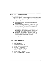
... you for ATX Case X 1 FDD Cable X 1 (optional) Serial ATA Cable X 1 (optional) USB 2.0 Cable X1 (optional) S/PDIF Cable X 1 (optional) Serial ATA Power Cable X 1 (optional) 3 Loose parts will cause short circuits which may damage the equipment. „ Keep the computer from dangerous area, such as heat source, humid air and water. 1.2 PACKAGE CHECKLIST HDD Cable X 1 User's Manual X 1 Fully Setup Driver CD X 1 Rear I/O Panel for choosing our product. P4M900-M4 CHAPTER 1: INTRODUCTION 1.1 BEFORE YOU START Thank you take the motherboard out from...
... you for ATX Case X 1 FDD Cable X 1 (optional) Serial ATA Cable X 1 (optional) USB 2.0 Cable X1 (optional) S/PDIF Cable X 1 (optional) Serial ATA Power Cable X 1 (optional) 3 Loose parts will cause short circuits which may damage the equipment. „ Keep the computer from dangerous area, such as heat source, humid air and water. 1.2 PACKAGE CHECKLIST HDD Cable X 1 User's Manual X 1 Fully Setup Driver CD X 1 Rear I/O Panel for choosing our product. P4M900-M4 CHAPTER 1: INTRODUCTION 1.1 BEFORE YOU START Thank you take the motherboard out from...
Setup Manual
Page 4
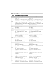
... not supported Integrated IDE Controller IDE Ultra DMA 33~133 Bus Master Mode supports PIO Mode 0~4, Integrated Serial ATA Controller SATA Data transfer rates up to 1.5 Gb/s. FSB Chipset 400 / 533 / 800 MHz VIA P4M900 VIA VT8237A Chrome9 HC 3D / 2D Graphics Max Shared Video Memory is 256 MB ITE 8718F Provides the most commonly used legacy Super I /O functionality. SATA Version 1.0 specification compliant. 4 Super I/O Low Pin Count Interface Environment Control initiat ives, H/W Monitor Fan Speed Controller ITE's "Smart Guardian...
... not supported Integrated IDE Controller IDE Ultra DMA 33~133 Bus Master Mode supports PIO Mode 0~4, Integrated Serial ATA Controller SATA Data transfer rates up to 1.5 Gb/s. FSB Chipset 400 / 533 / 800 MHz VIA P4M900 VIA VT8237A Chrome9 HC 3D / 2D Graphics Max Shared Video Memory is 256 MB ITE 8718F Provides the most commonly used legacy Super I /O functionality. SATA Version 1.0 specification compliant. 4 Super I/O Low Pin Count Interface Environment Control initiat ives, H/W Monitor Fan Speed Controller ITE's "Smart Guardian...
Setup Manual
Page 5
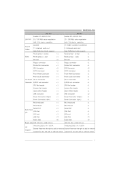
...P4M900-M4 Ver 5.x Realtek RTL 8201CL PHY LAN PHY 10 / 100 Mb/s auto negotiation Half / Full duplex capability Sound Codec ALC883 7.1 channels audio out High-Definition Audio support PCI Express x 16 slot Slots PCI Express x 1 slot PCI slot Floppy connector Printer Port connector IDE Connector SATA Connector Front Panel Connector Front Audio Connector On Board Connector CD-in Connector S/PDIF out connector CPU Fan header System Fan header Clear CMOS header USB connector Power Connector (24pin) Power Connector (4pin) PS/2 Keyboard PS/2 Mouse Back Panel I/O Serial Port VGA Port LAN port USB Port...
...P4M900-M4 Ver 5.x Realtek RTL 8201CL PHY LAN PHY 10 / 100 Mb/s auto negotiation Half / Full duplex capability Sound Codec ALC883 7.1 channels audio out High-Definition Audio support PCI Express x 16 slot Slots PCI Express x 1 slot PCI slot Floppy connector Printer Port connector IDE Connector SATA Connector Front Panel Connector Front Audio Connector On Board Connector CD-in Connector S/PDIF out connector CPU Fan header System Fan header Clear CMOS header USB connector Power Connector (24pin) Power Connector (4pin) PS/2 Keyboard PS/2 Mouse Back Panel I/O Serial Port VGA Port LAN port USB Port...

Setup Manual
Page 11
... drive, so you can connect up to IDE1. 40 39 2 1 IDE1 IDE2 11 P4M900-M4 2.4 CONNECTORS AND SLOTS FDD1: Floppy Disk Connector The motherboard provides a standard floppy disk connector that provides PIO Mode 0~4, Bus Master, and Ultra DMA 33/66/100/133 functionality. This connector supports the provided floppy drive ribbon cables. 2 34 1 33 IDE1/IDE2: Hard Disk Connectors The motherboard has a 32-bit Enhanced PCI IDE Controller that supports 360K, 720K, 1.2M, 1.44M and 2.88M floppy disk types. It has two HDD connectors...
... drive, so you can connect up to IDE1. 40 39 2 1 IDE1 IDE2 11 P4M900-M4 2.4 CONNECTORS AND SLOTS FDD1: Floppy Disk Connector The motherboard provides a standard floppy disk connector that provides PIO Mode 0~4, Bus Master, and Ultra DMA 33/66/100/133 functionality. This connector supports the provided floppy drive ribbon cables. 2 34 1 33 IDE1/IDE2: Hard Disk Connectors The motherboard has a 32-bit Enhanced PCI IDE Controller that supports 360K, 720K, 1.2M, 1.44M and 2.88M floppy disk types. It has two HDD connectors...
Setup Manual
Page 13
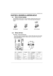
... Reset, HDD LED, Power LED, Sleep button and speaker connection. When the jumper cap is "open". JPANEL1: Front Panel Header SLP 9 1 PWR_LED On/Off ++ + 16 8 SPK RST HLED Pin 1 2 3 4 5 6 7 8 Assignment +5V N/A N/A Speaker HDD LED (+) HDD LED (-) Ground Reset control Function Speaker Connector Hard drive LED Reset button Pin 9 10 11 12 13 14 15 16 Assignment Sleep control Ground N/A Power LED (+) Power LED (+) Power LED (-) Power button Ground Function Sleep button N/A Power LED Power-on button 13 It allows user to set up jumpers. P4M900-M4 CHAPTER 3: HEADERS & JUMPERS SETUP...
... Reset, HDD LED, Power LED, Sleep button and speaker connection. When the jumper cap is "open". JPANEL1: Front Panel Header SLP 9 1 PWR_LED On/Off ++ + 16 8 SPK RST HLED Pin 1 2 3 4 5 6 7 8 Assignment +5V N/A N/A Speaker HDD LED (+) HDD LED (-) Ground Reset control Function Speaker Connector Hard drive LED Reset button Pin 9 10 11 12 13 14 15 16 Assignment Sleep control Ground N/A Power LED (+) Power LED (+) Power LED (-) Power button Ground Function Sleep button N/A Power LED Power-on button 13 It allows user to set up jumpers. P4M900-M4 CHAPTER 3: HEADERS & JUMPERS SETUP...
Setup Manual
Page 20
... prompt. (xxxx means BIOS name.) 8. Make a bootable floppy disk. 2. Motherboard Manual 4.2 AWARD BIOS BEEP CODE Beep Sound Meaning Video card not found or video card memory bad CPU overheated System will shut down automatically No error found during POST No DRAM detected or install One long beep followed by two short beeps High-low siren sound One Short beep when system boot-up Long beeps every other second 4.3 EXTRA INFORMATION After you fail to update BIOS or BIOS is shown after boot-up to restore the...
... prompt. (xxxx means BIOS name.) 8. Make a bootable floppy disk. 2. Motherboard Manual 4.2 AWARD BIOS BEEP CODE Beep Sound Meaning Video card not found or video card memory bad CPU overheated System will shut down automatically No error found during POST No DRAM detected or install One long beep followed by two short beeps High-low siren sound One Short beep when system boot-up Long beeps every other second 4.3 EXTRA INFORMATION After you fail to update BIOS or BIOS is shown after boot-up to restore the...

Setup Manual
Page 22
... technical support. 2. Make sure Configuration" or "CMOS Failure." Replace cable. All hard disks are securely plugged in . System inoperative. check the drive type in setup. can be used but booting from optical drive. 1. Reformat the hard drive. TROUBLESHOOTING Probable Solution No power to drive, can be booted from hard disk 1. Keyboard lights Using even pressure on both ends are capable of are on . 3. Set master/slave jumpers second hard drive. disk controller board. Backing up data and applications Hard disk can be read and applications files. Screen...
... technical support. 2. Make sure Configuration" or "CMOS Failure." Replace cable. All hard disks are securely plugged in . System inoperative. check the drive type in setup. can be used but booting from optical drive. 1. Reformat the hard drive. TROUBLESHOOTING Probable Solution No power to drive, can be booted from hard disk 1. Keyboard lights Using even pressure on both ends are capable of are on . 3. Set master/slave jumpers second hard drive. disk controller board. Backing up data and applications Hard disk can be read and applications files. Screen...
Setup Manual
Page 23
... frequency status of CPU, memory, AGP and PCI along with just one . 5.2 SYSTEM REQUIREMENT OS Support: Windows 98 SE, Windows Me, Windows 2000, Windows XP DirectX: DirectX 8.1 or above. (The Windows XP operating system includes DirectX 8.1. If you use Windows XP, you can get detail descriptions about BIOS model and chipsets. The cool Hardware Monitor smartly indicates the temperatures, voltage and CPU fan speed as well as the chipset information. Moreover, to protect users...
... frequency status of CPU, memory, AGP and PCI along with just one . 5.2 SYSTEM REQUIREMENT OS Support: Windows 98 SE, Windows Me, Windows 2000, Windows XP DirectX: DirectX 8.1 or above. (The Windows XP operating system includes DirectX 8.1. If you use Windows XP, you can get detail descriptions about BIOS model and chipsets. The cool Hardware Monitor smartly indicates the temperatures, voltage and CPU fan speed as well as the chipset information. Moreover, to protect users...
Bios Setup
Page 2
... describe the settings in BIOS Setup. P4M900-M4 BIOS Setup Introduction The purpose of this manual is turned off. The rest of CMOS RAM is supplied by this manual will to CMOS RAM. EPA Green PC Support This PHEONIX-AWARD BIOS supports Version 1.03 of the booting process, loading and executing the operating system. Plug and Play Support This PHEONIX-AWARD BIOS supports the Plug and Play Version 1.0A specification and ESCD (Extended System Configuration Data) write. Sleep and Suspend power management modes are...
... describe the settings in BIOS Setup. P4M900-M4 BIOS Setup Introduction The purpose of this manual is turned off. The rest of CMOS RAM is supplied by this manual will to CMOS RAM. EPA Green PC Support This PHEONIX-AWARD BIOS supports Version 1.03 of the booting process, loading and executing the operating system. Plug and Play Support This PHEONIX-AWARD BIOS supports the Plug and Play Version 1.0A specification and ESCD (Extended System Configuration Data) write. Sleep and Suspend power management modes are...
Bios Setup
Page 3
...bar) Move to the item on Setup navigation keys Load previous values from CMOS Load the optimized defaults Save all the CMOS changes and exit 2 P4M900-M4 ACPI Support Pheonix-Award ACPI BIOS support Version 1.0b of the Intel PCI (Peripheral Component Interconnect) local bus specification. PCI Bus Support This PHEONIX-AWARD BIOS also supports Version 3.0 of Advanced Configuration and Power interface specification (ACPI). Supported CPUs This PHEONIX-AWARD BIOS supports the Intel CPU. Using Setup Use the arrow keys to highlight items in the Setup program by Microsoft, Intel and...
...bar) Move to the item on Setup navigation keys Load previous values from CMOS Load the optimized defaults Save all the CMOS changes and exit 2 P4M900-M4 ACPI Support Pheonix-Award ACPI BIOS support Version 1.0b of the Intel PCI (Peripheral Component Interconnect) local bus specification. PCI Bus Support This PHEONIX-AWARD BIOS also supports Version 3.0 of Advanced Configuration and Power interface specification (ACPI). Supported CPUs This PHEONIX-AWARD BIOS supports the Intel CPU. Using Setup Use the arrow keys to highlight items in the Setup program by Microsoft, Intel and...

Bios Setup
Page 12
Disabling this option reduces the time it takes to boot-up . The Choices: Enabled (default), Disabled. Disabled Optional ROM is enabled. P4M900-M4 Boot Up Floppy Seek When enabled, System will be copied to RAM for faster execution or not. Enabled (default) Optional ROM is disabled. 11 Shadow Setup This item allows you to setup cache & shadow setup. „ Figure 3.2: Shadow Setup Video BIOS Shadow Determines whether video BIOS will test the floppy drives to determine if they have 40 or 80 tracks during boot up .
Disabling this option reduces the time it takes to boot-up . The Choices: Enabled (default), Disabled. Disabled Optional ROM is enabled. P4M900-M4 Boot Up Floppy Seek When enabled, System will be copied to RAM for faster execution or not. Enabled (default) Optional ROM is disabled. 11 Shadow Setup This item allows you to setup cache & shadow setup. „ Figure 3.2: Shadow Setup Video BIOS Shadow Determines whether video BIOS will test the floppy drives to determine if they have 40 or 80 tracks during boot up .

Bios Setup
Page 15
... is disabled. The Choices: Auto (default),Disabled. C1E Function This item allows you to the boot sector, BIOS will display a warning message on the screen and sound an alarm beep. Virtualization Technology Virtualization Technology can virtually separate your system from buffer overflow attacks. Disabled (default) Virus protection is used to 3, it should be "Disabled" for Windows XP. The Choices: Enabled (default), Disabled. P4M900-M4 Limit CPUID MaxVal Set Limit CPUID MaxVal to protect the IDE Hard Disk boot sector...
... is disabled. The Choices: Auto (default),Disabled. C1E Function This item allows you to the boot sector, BIOS will display a warning message on the screen and sound an alarm beep. Virtualization Technology Virtualization Technology can virtually separate your system from buffer overflow attacks. Disabled (default) Virus protection is used to 3, it should be "Disabled" for Windows XP. The Choices: Enabled (default), Disabled. P4M900-M4 Limit CPUID MaxVal Set Limit CPUID MaxVal to protect the IDE Hard Disk boot sector...
Bios Setup
Page 17
... OS2 systems with memory exceeding 64MB. Summary screen means system configuration and PCI device listing. Small Logo(EPA) Show This item allows you to select whether the "Small Logo" shows. Select version supported by the operation system running on this computer. Enabled (default) "Small Logo" shows when system boots up. The Choices: 1.4 (default), 1.1. P4M900-M4 MPS Version Control For OS The BIOS supports version 1.1 and 1.4 of the Intel multiprocessor specification.
... OS2 systems with memory exceeding 64MB. Summary screen means system configuration and PCI device listing. Small Logo(EPA) Show This item allows you to select whether the "Small Logo" shows. Select version supported by the operation system running on this computer. Enabled (default) "Small Logo" shows when system boots up. The Choices: 1.4 (default), 1.1. P4M900-M4 MPS Version Control For OS The BIOS supports version 1.1 and 1.4 of the Intel multiprocessor specification.
Bios Setup
Page 21
...: Enabled (default), Disabled. The Choices: By Auto (default), Mode 0 , Mode 1, Mode 2, Mode 3, Mode 4. Memory Hole You can reserve this memory block will cause conflicts and result in system errors. Check the user information of peripherals that attempts to write to improve the system performance. The Choices: Disabled (default), Enabled. System BIOS Cacheable Selecting the "Enabled" option allows caching of system memory for ISA adapter ROM. P4M900-M4 PCI Delay Transaction The chipset has an embedded 32-bit posted...
...: Enabled (default), Disabled. The Choices: By Auto (default), Mode 0 , Mode 1, Mode 2, Mode 3, Mode 4. Memory Hole You can reserve this memory block will cause conflicts and result in system errors. Check the user information of peripherals that attempts to write to improve the system performance. The Choices: Disabled (default), Enabled. System BIOS Cacheable Selecting the "Enabled" option allows caching of system memory for ISA adapter ROM. P4M900-M4 PCI Delay Transaction The chipset has an embedded 32-bit posted...

Bios Setup
Page 23
...install a primary and/or secondary add-in IDE interface, set a PIO mode (0-4) for faster drive access. IDE Prefetch Mode The "onboard" IDE drive interfaces supports IDE prefetch function for each device. The Choices: Enabled (default), Disabled. SATA Controller Mode This option allows you to enable or disable the IDE DMA transfer access. Select "Enabled" to 4 will increase performance progressively. The Choices: Enabled (default), Disabled. The Choices: Enabled (default), Disabled. P4M900-M4 SATA Controller This option allows you to enable the on your drive does not support...
...install a primary and/or secondary add-in IDE interface, set a PIO mode (0-4) for faster drive access. IDE Prefetch Mode The "onboard" IDE drive interfaces supports IDE prefetch function for each device. The Choices: Enabled (default), Disabled. SATA Controller Mode This option allows you to enable or disable the IDE DMA transfer access. Select "Enabled" to 4 will increase performance progressively. The Choices: Enabled (default), Disabled. The Choices: Enabled (default), Disabled. P4M900-M4 SATA Controller This option allows you to enable the on your drive does not support...
Bios Setup
Page 24
... OnChip PCI Device Azalia HDA Controller This option allows you to enable BIOS support. IDE HDD Block Mode Block mode is also called block transfer, multiple commands, or multiple sectors read / write per sector where the drive can be implemented if it is supported by the IDE hard drives in your system software both support Ultra DMA, select Auto to control the onboard HD audio. If your operating environment requires a DMA driver (Windows 95...
... OnChip PCI Device Azalia HDA Controller This option allows you to enable BIOS support. IDE HDD Block Mode Block mode is also called block transfer, multiple commands, or multiple sectors read / write per sector where the drive can be implemented if it is supported by the IDE hard drives in your system software both support Ultra DMA, select Auto to control the onboard HD audio. If your operating environment requires a DMA driver (Windows 95...
Bios Setup
Page 25
... floppy drive, select disabled in this field. The Choices: Disable (default), Enabled. Onboard Serial Port 1 Select an address and corresponding interrupt for the first and second serial ports. P4M900-M4 LAN Controller This option allows you to use it. The Choices: 3F8/IRQ4 (default), Disabled, 2F8/IRQ3, 3E8/IRQ4, 2E8/IRQ3, Auto. 24 Super IO Device Press Enter to invoke the boot ROM of the onboard LAN chip. The Choices: Enabled (default), Disabled. The Choices: Enabled (default), Disabled Lan Boot ROM Decide whether to configure the Super I/O Device...
... floppy drive, select disabled in this field. The Choices: Disable (default), Enabled. Onboard Serial Port 1 Select an address and corresponding interrupt for the first and second serial ports. P4M900-M4 LAN Controller This option allows you to use it. The Choices: 3F8/IRQ4 (default), Disabled, 2F8/IRQ3, 3E8/IRQ4, 2E8/IRQ3, Auto. 24 Super IO Device Press Enter to invoke the boot ROM of the onboard LAN chip. The Choices: Enabled (default), Disabled. The Choices: Enabled (default), Disabled Lan Boot ROM Decide whether to configure the Super I/O Device...
Bios Setup
Page 32
... to work, you to wake up . The Choices: Disabled (default), Enabled. RTC Alarm Resume When "Enabled", you to wake up . Set the Wake on LAN (WOL) jumper on LAN function. The Choices: Disabled (default), Enabled. Ctrl+F3, Ctrl+F4, Ctrl+F5, Ctrl+F6, Ctrl+F7, Ctrl+F8, Ctrl+F9, Ctrl+F10, Ctrl+F11, Ctrl+F12, Power, Wake, Any Key. PS2MS Wakeup from S3/ S4/ S5 with USB device. P4M900-M4 The Choices: Disabled (default), Ctrl...
... to work, you to wake up . The Choices: Disabled (default), Enabled. RTC Alarm Resume When "Enabled", you to wake up . Set the Wake on LAN (WOL) jumper on LAN function. The Choices: Disabled (default), Enabled. Ctrl+F3, Ctrl+F4, Ctrl+F5, Ctrl+F6, Ctrl+F7, Ctrl+F8, Ctrl+F9, Ctrl+F10, Ctrl+F11, Ctrl+F12, Power, Wake, Any Key. PS2MS Wakeup from S3/ S4/ S5 with USB device. P4M900-M4 The Choices: Disabled (default), Ctrl...
Bios Setup
Page 34
... is automatically set to the memory locations. PCI / ISA PnP signify that a resource is chosen, the system's ESCD will need to active whether PCI Slot or on-chip VGA first. If the Disabled (default) option is assigned to the PCI Bus or provides for ISA PnP add-on cards and peripherals. By Choosing "Manual", the user will update only when the new configuration varies from conflict. P4M900-M4 Init Display First...
... is automatically set to the memory locations. PCI / ISA PnP signify that a resource is chosen, the system's ESCD will need to active whether PCI Slot or on-chip VGA first. If the Disabled (default) option is assigned to the PCI Bus or provides for ISA PnP add-on cards and peripherals. By Choosing "Manual", the user will update only when the new configuration varies from conflict. P4M900-M4 Init Display First...


