User Manual
Page 3
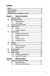
Contents Notices...vi Safety information vii About this guide vii P8H67-M LE Series specifications summary ix Chapter 1: Product introduction 1.1 Before you proceed 1-1 1.2 Motherboard overview 1-2 1.2.1 Motherboard layout 1-2 1.2.2 Layout contents 1-2 1.3 Central Processing Unit (CPU 1-3 1.4 System memory 1-3 1.4.1 Overview 1-3 1.4.2 ... Software support 1-19 1.10.1 Installing an operating system 1-19 1.10.2 Support DVD information 1-19 Chapter 2: BIOS information 2.1 Managing and updating your BIOS 2-1 2.1.1 ASUS Update utility 2-1 2.1.2 ASUS CrashFree BIOS 3 utility 2-2 iii
Contents Notices...vi Safety information vii About this guide vii P8H67-M LE Series specifications summary ix Chapter 1: Product introduction 1.1 Before you proceed 1-1 1.2 Motherboard overview 1-2 1.2.1 Motherboard layout 1-2 1.2.2 Layout contents 1-2 1.3 Central Processing Unit (CPU 1-3 1.4 System memory 1-3 1.4.1 Overview 1-3 1.4.2 ... Software support 1-19 1.10.1 Installing an operating system 1-19 1.10.2 Support DVD information 1-19 Chapter 2: BIOS information 2.1 Managing and updating your BIOS 2-1 2.1.1 ASUS Update utility 2-1 2.1.2 ASUS CrashFree BIOS 3 utility 2-2 iii

User Manual
Page 9
... resolution up to 16GB system memory * The maximum 32GB memory capacity can be supported with max.resolution up to www.asus.com for Intel® CPU support list. ASUS will update the memory QVL once the DIMMs are using a Windows® 32-bit operating system. 1 x PCI ... and 10 Realtek® 8112L Gigabit LAN controller ALC887 8-channel High Definition Audio CODEC For P8H67M LE: - 2 x USB 3.0/2.0 ports (blue, at the back I/O) - 12 x USB 2.0/1.1 ports (8 ports at mid-board, 4 ports at the back panel) For P8H67-M LX: - 14 x USB 2.0/1.1 ports (8 ports at mid-board, 6 ports at the back...
... resolution up to 16GB system memory * The maximum 32GB memory capacity can be supported with max.resolution up to www.asus.com for Intel® CPU support list. ASUS will update the memory QVL once the DIMMs are using a Windows® 32-bit operating system. 1 x PCI ... and 10 Realtek® 8112L Gigabit LAN controller ALC887 8-channel High Definition Audio CODEC For P8H67M LE: - 2 x USB 3.0/2.0 ports (blue, at the back I/O) - 12 x USB 2.0/1.1 ports (8 ports at mid-board, 4 ports at the back panel) For P8H67-M LX: - 14 x USB 2.0/1.1 ports (8 ports at mid-board, 6 ports at the back...
User Manual
Page 10
... MemOK! Anti-Surge protection ASUS CrashFree BIOS 3 ASUS MyLogo 2 ASUS Q-Fan2 4 x USB 2.0/1.1 connectors support additional 8 USB 2.0/1.1 ports 1 x System panel connector 1 x S/PDIF Out connector (for P8H67-M LE only) 4 x SATA 3.0 Gb/s connectors 2 x SATA 6.0 Gb/s connectors 1 x Front panel audio connector 1 x CPU fan connector 1 x Chassis fan connector 1 x Speaker connector 1 x COM connector (for P8H67-M LX only) 1 X LPT connector (for P8H67-M LX only) 1 x 24-pin...
... MemOK! Anti-Surge protection ASUS CrashFree BIOS 3 ASUS MyLogo 2 ASUS Q-Fan2 4 x USB 2.0/1.1 connectors support additional 8 USB 2.0/1.1 ports 1 x System panel connector 1 x S/PDIF Out connector (for P8H67-M LE only) 4 x SATA 3.0 Gb/s connectors 2 x SATA 6.0 Gb/s connectors 1 x Front panel audio connector 1 x CPU fan connector 1 x Chassis fan connector 1 x Speaker connector 1 x COM connector (for P8H67-M LX only) 1 X LPT connector (for P8H67-M LX only) 1 x 24-pin...
User Manual
Page 11
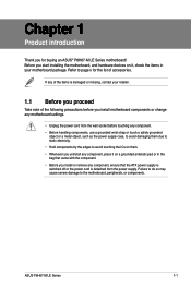
... the ATX power supply is switched off or the power cord is damaged or missing, contact your motherboard package. Refer to page x for buying an ASUS® P8H67-M LE Series motherboard! Failure to do so may cause severe damage to avoid touching the ICs on them due to static electricity. • Hold components... the list of the following precautions before you install motherboard components or change any motherboard settings. • Unplug the power cord from the power supply. ASUS P8H67-M LE Series 1-1
... the ATX power supply is switched off or the power cord is damaged or missing, contact your motherboard package. Refer to page x for buying an ASUS® P8H67-M LE Series motherboard! Failure to do so may cause severe damage to avoid touching the ICs on them due to static electricity. • Hold components... the list of the following precautions before you install motherboard components or change any motherboard settings. • Unplug the power cord from the power supply. ASUS P8H67-M LE Series 1-1
User Manual
Page 13
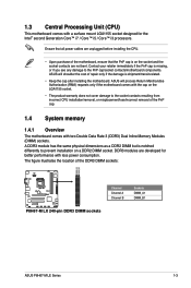
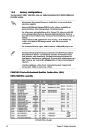
... immediately if the PnP cap is notched differently to the PnP cap/socket contacts/motherboard components. ASUS will process Return Merchandise Authorization (RMA) requests only if the motherboard comes with the cap on a DDR2 DIMM socket...from incorrect CPU installation/removal, or misplacement/loss/incorrect removal of the DDR3 DIMM sockets: DIMM_A1 DIMM_B1 P8H67-M LX Channel Channel A Channel B Sockets DIMM_A1 DIMM_B1 P8H67-M LX 240-pin DDR3 DIMM sockets ASUS P8H67-M LE Series 1-3 1.3 Central Processing Unit (CPU) This motherboard comes with a surface mount LGA1155 socket ...
... immediately if the PnP cap is notched differently to the PnP cap/socket contacts/motherboard components. ASUS will process Return Merchandise Authorization (RMA) requests only if the motherboard comes with the cap on a DDR2 DIMM socket...from incorrect CPU installation/removal, or misplacement/loss/incorrect removal of the DDR3 DIMM sockets: DIMM_A1 DIMM_B1 P8H67-M LX Channel Channel A Channel B Sockets DIMM_A1 DIMM_B1 P8H67-M LX 240-pin DDR3 DIMM sockets ASUS P8H67-M LE Series 1-3 1.3 Central Processing Unit (CPU) This motherboard comes with a surface mount LGA1155 socket ...
User Manual
Page 14
... the next page Timing 8-8-8-24 8-8-8-24 9 9-9-9-24 9-9-9-24 9-9-9-24 9-9-9-24 9-9-9-24 9-9-9-24 9-9-9-24 9-9-9-24 9 9 7-7-7-24 - - - J1108EDSE-DJ-F 2GB DS ELPIDA J1108EDSE-DJ-F 1GB SS G.SKILL - P8H67-M LE Series Motherboard Qualified Vendors Lists (QVL) DDR3-1333 MHz capability Vendors A-Data A-Data A-Data A-Data Apacer Apacer CORSAIR CORSAIR CORSAIR CORSAIR CORSAIR CORSAIR CORSAIR CORSAIR...
... the next page Timing 8-8-8-24 8-8-8-24 9 9-9-9-24 9-9-9-24 9-9-9-24 9-9-9-24 9-9-9-24 9-9-9-24 9-9-9-24 9-9-9-24 9 9 7-7-7-24 - - - J1108EDSE-DJ-F 2GB DS ELPIDA J1108EDSE-DJ-F 1GB SS G.SKILL - P8H67-M LE Series Motherboard Qualified Vendors Lists (QVL) DDR3-1333 MHz capability Vendors A-Data A-Data A-Data A-Data Apacer Apacer CORSAIR CORSAIR CORSAIR CORSAIR CORSAIR CORSAIR CORSAIR CORSAIR...

User Manual
Page 15
... DS 4GB(2x2GB) DS - Samsung K4B1G0846F Samsung K4B2G0846C Micron 0BF27D9KPT Micron 9GF27D9KPT Elpida J1108BDBG-DJ-F Elixir N2CB2G808N-CG - - Size SS/ Chip DS Brand Chip No. ASUS P8H67-M LE Series 1-5 GL1L128M88BA12N GEIL GV34GB1333C9DC 4GB(2x2GB) DS - - DDR3-1333 MHz capability Vendors Part No. PSC A3P1GF3DGF928M9B05 PSC A3P1GF3DGF928M9B05 SAMSUNG K4B1G0846F SAMSUNG K4B1G0846F SAMSUNG K4B2G0846C HYNIX...
... DS 4GB(2x2GB) DS - Samsung K4B1G0846F Samsung K4B2G0846C Micron 0BF27D9KPT Micron 9GF27D9KPT Elpida J1108BDBG-DJ-F Elixir N2CB2G808N-CG - - Size SS/ Chip DS Brand Chip No. ASUS P8H67-M LE Series 1-5 GL1L128M88BA12N GEIL GV34GB1333C9DC 4GB(2x2GB) DS - - DDR3-1333 MHz capability Vendors Part No. PSC A3P1GF3DGF928M9B05 PSC A3P1GF3DGF928M9B05 SAMSUNG K4B1G0846F SAMSUNG K4B1G0846F SAMSUNG K4B2G0846C HYNIX...
User Manual
Page 17
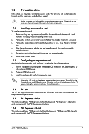
... came with the PCI Express specifications. 1.5.3 PCI Express x16 slot This motherboard has a PCI Express 2.0 x16 slot that they support. See Chapter 2 for later use . ASUS P8H67-M LE Series 1-7 Replace the system cover. 1.5.2 Configuring an expansion card After installing the expansion card, configure it and make the necessary hardware settings for the expansion...
... came with the PCI Express specifications. 1.5.3 PCI Express x16 slot This motherboard has a PCI Express 2.0 x16 slot that they support. See Chapter 2 for later use . ASUS P8H67-M LE Series 1-7 Replace the system cover. 1.5.2 Configuring an expansion card After installing the expansion card, configure it and make the necessary hardware settings for the expansion...

User Manual
Page 19
... BLINKING Data activity SPEED LED Status Description OFF 10 Mbps connection ORANGE 100 Mbps connection GREEN 1 Gbps connection ACT/LINK SPEED LED LED LAN port ASUS P8H67-M LE Series 1-9 PS/2 Keyboard port. This 15-pin port is for a VGA monitor or other VGA-compatible devices. 3. 1.7 1.7.1 1 Connectors Rear panel connectors 2 3 45 11 9 8 7 6 1 2 3 45 11...
... BLINKING Data activity SPEED LED Status Description OFF 10 Mbps connection ORANGE 100 Mbps connection GREEN 1 Gbps connection ACT/LINK SPEED LED LED LAN port ASUS P8H67-M LE Series 1-9 PS/2 Keyboard port. This 15-pin port is for a VGA monitor or other VGA-compatible devices. 3. 1.7 1.7.1 1 Connectors Rear panel connectors 2 3 45 11 9 8 7 6 1 2 3 45 11...
User Manual
Page 20
...Side Speaker Out To configure an 8-channel audio output: Use a chassis with DVI-I. 1-10 Chapter 1: Product introduction USB 3.0 ports 3 and 4 (for P8H67-M LX only). DVI-D port. USB 2.0 ports 1 and 2. These two 9-pin Universal Serial Bus (USB) ports are for your USB 3.0 devices. USB 2.0 ports 3... and 4 (for P8H67-M LE only). Microphone port (pink). DVI-D cannot be used under Windows® OS environment and after the USB 3.0 driver installation. • USB 3.0 devices ...
...Side Speaker Out To configure an 8-channel audio output: Use a chassis with DVI-I. 1-10 Chapter 1: Product introduction USB 3.0 ports 3 and 4 (for P8H67-M LX only). DVI-D port. USB 2.0 ports 1 and 2. These two 9-pin Universal Serial Bus (USB) ports are for your USB 3.0 devices. USB 2.0 ports 3... and 4 (for P8H67-M LE only). Microphone port (pink). DVI-D cannot be used under Windows® OS environment and after the USB 3.0 driver installation. • USB 3.0 devices ...

User Manual
Page 21
...) ports are designed to fit these connectors in only one orientation. Find the proper orientation and push down firmly until the connectors completely fit. ASUS P8H67-M LE Series 1-11 The power supply plugs are available for your system, refer to connect the 4-pin/8-pin ATX +12V power plug. HDMI port ... GND GND GND +3 Volts +12 Volts +12 Volts +5V Standby Power OK PIN 1 GND +5 Volts GND +5 Volts GND +3 Volts +3 Volts PIN 1 P8H67-M LX ATX power connectors GND +5 Volts +5 Volts +5 Volts -5 Volts GND GND GND PSON# GND -12 Volts +3 Volts • For a fully configured system, ...
...) ports are designed to fit these connectors in only one orientation. Find the proper orientation and push down firmly until the connectors completely fit. ASUS P8H67-M LE Series 1-11 The power supply plugs are available for your system, refer to connect the 4-pin/8-pin ATX +12V power plug. HDMI port ... GND GND GND +3 Volts +12 Volts +12 Volts +5V Standby Power OK PIN 1 GND +5 Volts GND +5 Volts GND +3 Volts +3 Volts PIN 1 P8H67-M LX ATX power connectors GND +5 Volts +5 Volts +5 Volts -5 Volts GND GND GND PSON# GND -12 Volts +3 Volts • For a fully configured system, ...
User Manual
Page 22
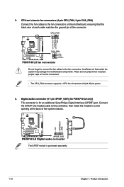
...air flow inside the system may damage the motherboard components. CPU_FAN CPU FAN PWM CPU FAN IN CPU FAN PWR GND P8H67-M LX CHA_FAN GND +12V Rotation P8H67-M LX fan connectors Do not forget to connect the fan cables to a slot opening at the back of the system chassis.... +5V SPDIFOUT GND P8H67-M LE SPDIF_OUT P8H67-M LE Digital audio connector The S/PDIF module is for P8H67-M LE only] This connector is purchased separately. 1-12 Chapter 1: ...
...air flow inside the system may damage the motherboard components. CPU_FAN CPU FAN PWM CPU FAN IN CPU FAN PWR GND P8H67-M LX CHA_FAN GND +12V Rotation P8H67-M LX fan connectors Do not forget to connect the fan cables to a slot opening at the back of the system chassis.... +5V SPDIFOUT GND P8H67-M LE SPDIF_OUT P8H67-M LE Digital audio connector The S/PDIF module is for P8H67-M LE only] This connector is purchased separately. 1-12 Chapter 1: ...
User Manual
Page 23
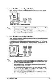
... you can connect Serial ATA boot/data hard disk drives to these connectors, set , refer to [AHCI Mode]. ASUS P8H67-M LE Series 1-13 See section 2.5.4 SATA Configuration for details. 5. SATA3G_1 SATA3G_2 GND RSATA_TXP1 RSATA_TXN1 GND RSATA_RXP1 RSATA_RXN1 GND GND RSATA_TXP2... RSATA_TXN2 GND RSATA_RXP2 RSATA_RXN2 GND P8H67-M LX SATA3G_3 SATA3G_4 GND RSATA_TXP3 RSATA_TXN3 GND RSATA_RXP3 RSATA_RXN3 GND GND RSATA_TXP4 RSATA_TXN4 GND RSATA_RXP4 RSATA_RXN4 GND P8H67-M LX SATA 3.0Gb/s connectors • These connectors are set the SATA...
... you can connect Serial ATA boot/data hard disk drives to these connectors, set , refer to [AHCI Mode]. ASUS P8H67-M LE Series 1-13 See section 2.5.4 SATA Configuration for details. 5. SATA3G_1 SATA3G_2 GND RSATA_TXP1 RSATA_TXN1 GND RSATA_RXP1 RSATA_RXN1 GND GND RSATA_TXP2... RSATA_TXN2 GND RSATA_RXP2 RSATA_RXN2 GND P8H67-M LX SATA3G_3 SATA3G_4 GND RSATA_TXP3 RSATA_TXN3 GND RSATA_RXP3 RSATA_RXN3 GND GND RSATA_TXP4 RSATA_TXN4 GND RSATA_RXP4 RSATA_RXN4 GND P8H67-M LX SATA 3.0Gb/s connectors • These connectors are set the SATA...

User Manual
Page 25
... GND SLIN# INIT# ERR# AFD SLCT PE BUSY ACK# PD7 PD6 PD5 PD4 PD3 PD2 PD1 PD0 STB# PIN 1 P8H67-M LX Parallel Port Connector ASUS P8H67-M LE Series 1-15 8. Ground Reset P8H67-M LX F_PANEL PIN 1 HD_LED RESET P8H67-M LX System panel connector • System power LED (2-pin PLED) This 2-pin connector is for the HDD Activity LED. The IDE...
... GND SLIN# INIT# ERR# AFD SLCT PE BUSY ACK# PD7 PD6 PD5 PD4 PD3 PD2 PD1 PD0 STB# PIN 1 P8H67-M LX Parallel Port Connector ASUS P8H67-M LE Series 1-15 8. Ground Reset P8H67-M LX F_PANEL PIN 1 HD_LED RESET P8H67-M LX System panel connector • System power LED (2-pin PLED) This 2-pin connector is for the HDD Activity LED. The IDE...
User Manual
Page 27
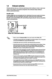
... version from the ASUS website at www.asus.com. • If you to test one set of the DRAM_LED. • The DRAM_LED also lights when the DIMM is ideal for overclockers and gamers who continually change settings to BIOS overclocking, press the MemOK! P8H67-M LX P8H67-M LX MemOK! function. ...due to enhance system performance. Replace the DIMMs with the motherboard may cause system boot failure, and the DRAM_LED near the MemOK! ASUS P8H67-M LE Series 1-17 switch • Refer to section 1.9 Onboard LEDs for the exact location of failsafe settings. If the installed DIMMs ...
... version from the ASUS website at www.asus.com. • If you to test one set of the DRAM_LED. • The DRAM_LED also lights when the DIMM is ideal for overclockers and gamers who continually change settings to BIOS overclocking, press the MemOK! P8H67-M LX P8H67-M LX MemOK! function. ...due to enhance system performance. Replace the DIMMs with the motherboard may cause system boot failure, and the DRAM_LED near the MemOK! ASUS P8H67-M LE Series 1-17 switch • Refer to section 1.9 Onboard LEDs for the exact location of failsafe settings. If the installed DIMMs ...
User Manual
Page 29
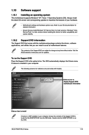
...the features of the Support DVD to avail all motherboard features. Double-click the ASSETUP.EXE to change at www.asus.com for better compatibility and system stability. 1.10.2 Support DVD information The Support DVD that comes with models. Visit the... the DVD. 1.10 Software support 1.10.1 Installing an operating system This motherboard supports Windows® XP / Vista / 7 Operating Systems (OS). ASUS P8H67-M LE Series 1-19 The DVD automatically displays the Drivers menu if Autorun is for reference only and varies with the motherboard package contains the drivers, software...
...the features of the Support DVD to avail all motherboard features. Double-click the ASSETUP.EXE to change at www.asus.com for better compatibility and system stability. 1.10.2 Support DVD information The Support DVD that comes with models. Visit the... the DVD. 1.10 Software support 1.10.1 Installing an operating system This motherboard supports Windows® XP / Vista / 7 Operating Systems (OS). ASUS P8H67-M LE Series 1-19 The DVD automatically displays the Drivers menu if Autorun is for reference only and varies with the motherboard package contains the drivers, software...
User Manual
Page 30
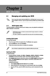
... utility. From the Windows® desktop, click Start > Programs > ASUS > AI Suite II > AI Suite II X.XX.XX to complete the installation. Select the ASUS FTP site nearest you to download then click Next. 2-1 ASUS P8H67-M LE Series c. From the FTP site, select the BIOS version that you ...wish to avoid network traffic, then click Next. Click Update button from the Quick Bar, and then click ASUS Update from the Internet...
... utility. From the Windows® desktop, click Start > Programs > ASUS > AI Suite II > AI Suite II X.XX.XX to complete the installation. Select the ASUS FTP site nearest you to download then click Next. 2-1 ASUS P8H67-M LE Series c. From the FTP site, select the BIOS version that you ...wish to avoid network traffic, then click Next. Click Update button from the Quick Bar, and then click ASUS Update from the Internet...
User Manual
Page 31
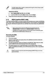
You can cause system boot failure! The utility automatically checks the devices for P8H67-M LX). • The BIOS file in the removable device into P8H67MLE.ROM (for P8H67-M LE) or P8H67MLX.ROM (for the BIOS file. Select Update BIOS from the ASUS website at www.asus.com. Download the latest BIOS file from file, then click Next...
You can cause system boot failure! The utility automatically checks the devices for P8H67-M LX). • The BIOS file in the removable device into P8H67MLE.ROM (for P8H67-M LE) or P8H67MLX.ROM (for the BIOS file. Select Update BIOS from the ASUS website at www.asus.com. Download the latest BIOS file from file, then click Next...
User Manual
Page 32
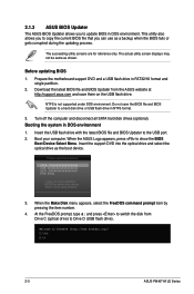
..., press to FreeDOS (http://www.freedos.org)! At the FreeDOS prompt, type d: and press to switch the disk from the ASUS website at http://support.asus.com and save the BIOS file and BIOS Updater to Drive D (USB flash drive). Welcome to show the BIOS Boot Device ...in DOS environment. Insert the USB flash drive with the latest BIOS file and BIOS Updater to boot using defaults 3. C:\>d: D:\> 2-3 ASUS P8H67-M LE Series 2.1.3 ASUS BIOS Updater The ASUS BIOS Updater allows you can use as a backup when the BIOS fails or gets corrupted during the updating process. The actual utility screen...
..., press to FreeDOS (http://www.freedos.org)! At the FreeDOS prompt, type d: and press to switch the disk from the ASUS website at http://support.asus.com and save the BIOS file and BIOS Updater to Drive D (USB flash drive). Welcome to show the BIOS Boot Device ...in DOS environment. Insert the USB flash drive with the latest BIOS file and BIOS Updater to boot using defaults 3. C:\>d: D:\> 2-3 ASUS P8H67-M LE Series 2.1.3 ASUS BIOS Updater The ASUS BIOS Updater allows you can use as a backup when the BIOS fails or gets corrupted during the updating process. The actual utility screen...
User Manual
Page 33
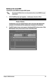
... any user-assigned filename with no more than eight alphanumeric characters for the filename and three alphanumeric characters for DOS V1.18 Current ROM BOARD: P8H67-M LE VER: 0218 DATE: 10/26/2010 Update ROM BOARD: Unknown VER: Unknown DATE: Unknown PATH: A:\ BIOS backup is not write-protected and has at least...
... any user-assigned filename with no more than eight alphanumeric characters for the filename and three alphanumeric characters for DOS V1.18 Current ROM BOARD: P8H67-M LE VER: 0218 DATE: 10/26/2010 Update ROM BOARD: Unknown VER: Unknown DATE: Unknown PATH: A:\ BIOS backup is not write-protected and has at least...


