User Manual
Page 3
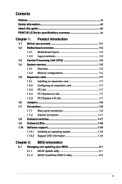
Contents Notices...vi Safety information vii About this guide vii P8H67-M LE Series specifications summary ix Chapter 1: Product introduction 1.1 Before you proceed 1-1 1.2 Motherboard overview 1-2 1.2.1 Motherboard layout 1-2 1.2.2 Layout contents 1-2 1.3 Central Processing Unit (CPU 1-3 1.4 System memory 1-3 1.4.1 Overview 1-3 1.4.2 Memory configurations 1-4 1.5 Expansion slots 1-7 1.5.1 Installing an ...1.10.2 Support DVD information 1-19 Chapter 2: BIOS information 2.1 Managing and updating your BIOS 2-1 2.1.1 ASUS Update utility 2-1 2.1.2 ASUS CrashFree BIOS 3 utility 2-2 iii
Contents Notices...vi Safety information vii About this guide vii P8H67-M LE Series specifications summary ix Chapter 1: Product introduction 1.1 Before you proceed 1-1 1.2 Motherboard overview 1-2 1.2.1 Motherboard layout 1-2 1.2.2 Layout contents 1-2 1.3 Central Processing Unit (CPU 1-3 1.4 System memory 1-3 1.4.1 Overview 1-3 1.4.2 Memory configurations 1-4 1.5 Expansion slots 1-7 1.5.1 Installing an ...1.10.2 Support DVD information 1-19 Chapter 2: BIOS information 2.1 Managing and updating your BIOS 2-1 2.1.1 ASUS Update utility 2-1 2.1.2 ASUS CrashFree BIOS 3 utility 2-2 iii
User Manual
Page 6
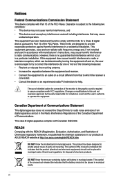
These limits are designed to provide reasonable protection against harmful interference in municipal waste. DO NOT throw the motherboard in a residential installation. This symbol of the FCC Rules. This class B digital apparatus complies with Part 15 of the crossed out wheeled bin indicates that ... cause harmful interference, and • This device must accept any interference received including interference that the battery should not be placed in our products at ASUS REACH website at http://csr.asus.com/english/REACH.htm.
These limits are designed to provide reasonable protection against harmful interference in municipal waste. DO NOT throw the motherboard in a residential installation. This symbol of the FCC Rules. This class B digital apparatus complies with Part 15 of the crossed out wheeled bin indicates that ... cause harmful interference, and • This device must accept any interference received including interference that the battery should not be placed in our products at ASUS REACH website at http://csr.asus.com/english/REACH.htm.

User Manual
Page 7
.... About this guide is organized This guide contains the following parts: • Chapter 1: Product introduction This chapter describes the features of the motherboard and the new technology it supports. • Chapter 2: BIOS information This chapter tells how to the correct voltage in any damage, contact your...retailer. How this guide This user guide contains the information you add a device. • Before connecting or removing signal cables from the motherboard, ensure that your area. Do not place the product in your power supply is broken, do not try to or from the system, ...
.... About this guide is organized This guide contains the following parts: • Chapter 1: Product introduction This chapter describes the features of the motherboard and the new technology it supports. • Chapter 2: BIOS information This chapter tells how to the correct voltage in any damage, contact your...retailer. How this guide This user guide contains the information you add a device. • Before connecting or removing signal cables from the motherboard, ensure that your area. Do not place the product in your power supply is broken, do not try to or from the system, ...
User Manual
Page 11
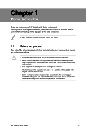
... so may cause severe damage to page x for the list of the following precautions before you for buying an ASUS® P8H67-M LE Series motherboard! Before you start installing the motherboard, and hardware devices on it on them. • Whenever you uninstall any component, place it , check the... pad or in your retailer. 1.1 Before you install or remove any of the items is damaged or missing, contact your motherboard package. If any component, ensure that came with the component. • Before you proceed Take note of accessories. ASUS P8H67-M LE Series 1-1 Refer to the...
... so may cause severe damage to page x for the list of the following precautions before you for buying an ASUS® P8H67-M LE Series motherboard! Before you start installing the motherboard, and hardware devices on it on them. • Whenever you uninstall any component, place it , check the... pad or in your retailer. 1.1 Before you install or remove any of the items is damaged or missing, contact your motherboard package. If any component, ensure that came with the component. • Before you proceed Take note of accessories. ASUS P8H67-M LE Series 1-1 Refer to the...
User Manual
Page 12
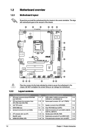
... LGA1155 USB34 MemOK! 7 DRAM_LED 8 LAN1_USB12 AUDIO RTL 8112L Asmedia ASM1083 ALC 887 AAFP CHA_FAN Lithium Cell CMOS Power P8H67-M LX PCIEX16 PCI1 PCI2 SB_PWR PCIEX4_1 USB1314 USB1112 USB910 Intel® H67 USB78 32Mb BIOS CLRTC SPEAKER F_PANEL SATA3G_3 SATA3G_1 SATA6G_1 ...pin EATXPWR, 8-pin EATX12V) 2. Intel® CPU socket 4. Serial port connector (10-1 pin COM1) 6. switch 8. Doing so can damage the motherboard. 1.2.2 Layout contents Connectors/Jumpers/Slots/LED 1. System panel connector (10-1 pin F_PANEL) Page 1-13 1-15 1-3 11. Front panel audio connector (...
... LGA1155 USB34 MemOK! 7 DRAM_LED 8 LAN1_USB12 AUDIO RTL 8112L Asmedia ASM1083 ALC 887 AAFP CHA_FAN Lithium Cell CMOS Power P8H67-M LX PCIEX16 PCI1 PCI2 SB_PWR PCIEX4_1 USB1314 USB1112 USB910 Intel® H67 USB78 32Mb BIOS CLRTC SPEAKER F_PANEL SATA3G_3 SATA3G_1 SATA6G_1 ...pin EATXPWR, 8-pin EATX12V) 2. Intel® CPU socket 4. Serial port connector (10-1 pin COM1) 6. switch 8. Doing so can damage the motherboard. 1.2.2 Layout contents Connectors/Jumpers/Slots/LED 1. System panel connector (10-1 pin F_PANEL) Page 1-13 1-15 1-3 11. Front panel audio connector (...
User Manual
Page 13
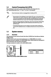
... the cost of the DDR3 DIMM sockets: DIMM_A1 DIMM_B1 P8H67-M LX Channel Channel A Channel B Sockets DIMM_A1 DIMM_B1 P8H67-M LX 240-pin DDR3 DIMM sockets ASUS P8H67-M LE Series 1-3 The figure illustrates the location of repair only if the damage is on the socket and the socket contacts ... is notched differently to prevent installation on the LGA1155 socket. • The product warranty does not cover damage to the PnP cap/socket contacts/motherboard components. DDR3 modules are not bent. A DDR3 module has the same physical dimensions as a DDR2 DIMM but is missing, or if you...
... the cost of the DDR3 DIMM sockets: DIMM_A1 DIMM_B1 P8H67-M LX Channel Channel A Channel B Sockets DIMM_A1 DIMM_B1 P8H67-M LX 240-pin DDR3 DIMM sockets ASUS P8H67-M LE Series 1-3 The figure illustrates the location of repair only if the damage is on the socket and the socket contacts ... is notched differently to prevent installation on the LGA1155 socket. • The product warranty does not cover damage to the PnP cap/socket contacts/motherboard components. DDR3 modules are not bent. A DDR3 module has the same physical dimensions as a DDR2 DIMM but is missing, or if you...
User Manual
Page 14
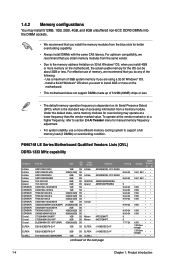
... system to the memory address limitation on 32-bit Windows® OS, when you install 4GB or more on the motherboard. • This motherboard does not support DIMMs made up of 512Mb (64MB) chips or less. • The default memory operation frequency is... the next page Timing 8-8-8-24 8-8-8-24 9 9-9-9-24 9-9-9-24 9-9-9-24 9-9-9-24 9-9-9-24 9-9-9-24 9-9-9-24 9-9-9-24 9 9 7-7-7-24 - - - P8H67-M LE Series Motherboard Qualified Vendors Lists (QVL) DDR3-1333 MHz capability Vendors A-Data A-Data A-Data A-Data Apacer Apacer CORSAIR CORSAIR CORSAIR CORSAIR CORSAIR CORSAIR CORSAIR CORSAIR CORSAIR...
... system to the memory address limitation on 32-bit Windows® OS, when you install 4GB or more on the motherboard. • This motherboard does not support DIMMs made up of 512Mb (64MB) chips or less. • The default memory operation frequency is... the next page Timing 8-8-8-24 8-8-8-24 9 9-9-9-24 9-9-9-24 9-9-9-24 9-9-9-24 9-9-9-24 9-9-9-24 9-9-9-24 9-9-9-24 9 9 7-7-7-24 - - - P8H67-M LE Series Motherboard Qualified Vendors Lists (QVL) DDR3-1333 MHz capability Vendors A-Data A-Data A-Data A-Data Apacer Apacer CORSAIR CORSAIR CORSAIR CORSAIR CORSAIR CORSAIR CORSAIR CORSAIR CORSAIR...
User Manual
Page 17
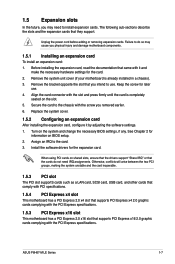
...for information on the system and change the necessary BIOS settings, if any. Turn on BIOS setup. 2. See Chapter 2 for later use . ASUS P8H67-M LE Series 1-7 Otherwise, conflicts will arise between the two PCI groups, making the system unstable and the card inoperable. 1.5.3 PCI slot The ... so may need IRQ assignments. Align the card connector with the screw you removed earlier. 6. Remove the system unit cover (if your motherboard is completely seated on shared slots, ensure that the drivers support "Share IRQ" or that they support. 1.5 Expansion slots In the future...
...for information on the system and change the necessary BIOS settings, if any. Turn on BIOS setup. 2. See Chapter 2 for later use . ASUS P8H67-M LE Series 1-7 Otherwise, conflicts will arise between the two PCI groups, making the system unstable and the card inoperable. 1.5.3 PCI slot The ... so may need IRQ assignments. Align the card connector with the screw you removed earlier. 6. Remove the system unit cover (if your motherboard is completely seated on shared slots, ensure that the drivers support "Share IRQ" or that they support. 1.5 Expansion slots In the future...
User Manual
Page 22
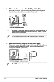
... may damage the motherboard components. Do not place jumper caps on the motherboard, ensuring that the black wire of each cable matches the ground pin of the connector. CPU_FAN CPU FAN PWM CPU FAN IN CPU FAN PWR GND P8H67-M LX CHA_FAN GND +12V Rotation P8H67-M LX fan connectors Do ... connectors on the fan connectors! • The CPU_FAN connector supports a CPU fan of the system chassis. +5V SPDIFOUT GND P8H67-M LE SPDIF_OUT P8H67-M LE Digital audio connector The S/PDIF module is for P8H67-M LE only] This connector is purchased separately. 1-12 Chapter 1: Product introduction
... may damage the motherboard components. Do not place jumper caps on the motherboard, ensuring that the black wire of each cable matches the ground pin of the connector. CPU_FAN CPU FAN PWM CPU FAN IN CPU FAN PWR GND P8H67-M LX CHA_FAN GND +12V Rotation P8H67-M LX fan connectors Do ... connectors on the fan connectors! • The CPU_FAN connector supports a CPU fan of the system chassis. +5V SPDIFOUT GND P8H67-M LE SPDIF_OUT P8H67-M LE Digital audio connector The S/PDIF module is for P8H67-M LE only] This connector is purchased separately. 1-12 Chapter 1: Product introduction
User Manual
Page 24
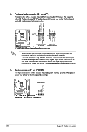
...to this connector, set the Front Panel Type item in the BIOS setup to this connector. P8H67-M LX P8H67-M LX Speaker connector 1-14 Chapter 1: Product introduction Connect one end of the motherboard's high-definition audio capability. • If you connect a high-definition front panel audio ... 1 PIN 1 MIC2 MICPWR Line out_R NC Line out_L PORT1 L PORT1 R PORT2 R SENSE_SEND PORT2 L P8H67-M LX HD-audio-compliant Legacy AC'97 pin definition compliant definition P8H67-M LX Front panel audio connector • We recommend that supports either HD Audio or legacy AC`97 audio standard....
...to this connector, set the Front Panel Type item in the BIOS setup to this connector. P8H67-M LX P8H67-M LX Speaker connector 1-14 Chapter 1: Product introduction Connect one end of the motherboard's high-definition audio capability. • If you connect a high-definition front panel audio ... 1 PIN 1 MIC2 MICPWR Line out_R NC Line out_L PORT1 L PORT1 R PORT2 R SENSE_SEND PORT2 L P8H67-M LX HD-audio-compliant Legacy AC'97 pin definition compliant definition P8H67-M LX Front panel audio connector • We recommend that supports either HD Audio or legacy AC`97 audio standard....
User Manual
Page 26
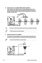
...NC USB+5V USB_P14USB_P14+ GND NC USB+5V USB_P7USB_P7+ GND P8H67-M LX USB1314 PIN 1 USB1112 PIN 1 USB910 PIN 1 USB78 PIN 1 USB+5V USB_P9USB_P9+ GND USB+5V USB_P11USB_P11+ GND USB+5V USB_P13USB_P13+ GND P8H67-M LX USB2.0 connectors Never connect a 1394 cable to 480 Mbps ... USB910, USB1112, USB1314 ) These connectors are for a serial (COM) port. COM1 PIN 1 P8H67-M LX P8H67-M LX Serial port (COM1) connector 1-16 Chapter 1: Product introduction Doing so will damage the motherboard! Connect the serial port module cable to the connector, then install the module to a slot opening...
...NC USB+5V USB_P14USB_P14+ GND NC USB+5V USB_P7USB_P7+ GND P8H67-M LX USB1314 PIN 1 USB1112 PIN 1 USB910 PIN 1 USB78 PIN 1 USB+5V USB_P9USB_P9+ GND USB+5V USB_P11USB_P11+ GND USB+5V USB_P13USB_P13+ GND P8H67-M LX USB2.0 connectors Never connect a 1394 cable to 480 Mbps ... USB910, USB1112, USB1314 ) These connectors are for a serial (COM) port. COM1 PIN 1 P8H67-M LX P8H67-M LX Serial port (COM1) connector 1-16 Chapter 1: Product introduction Doing so will damage the motherboard! Connect the serial port module cable to the connector, then install the module to a slot opening...
User Manual
Page 27
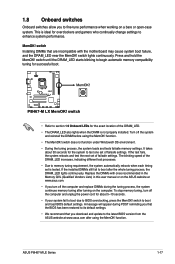
P8H67-M LX P8H67-M LX MemOK! Turn off the computer and replace DIMMs during POST reminding you that the BIOS has been restored to its default settings. • We recommend ... the installed DIMMs still fail to boot after turning on the computer. function. ASUS P8H67-M LE Series 1-17 To stop memory tuning, turn off the system and reinstall the DIMM before using the MemOK! Replace the DIMMs with the motherboard may cause system boot failure, and the DRAM_LED near the MemOK! switch Installing...
P8H67-M LX P8H67-M LX MemOK! Turn off the computer and replace DIMMs during POST reminding you that the BIOS has been restored to its default settings. • We recommend ... the installed DIMMs still fail to boot after turning on the computer. function. ASUS P8H67-M LE Series 1-17 To stop memory tuning, turn off the system and reinstall the DIMM before using the MemOK! Replace the DIMMs with the motherboard may cause system boot failure, and the DRAM_LED near the MemOK! switch Installing...
User Manual
Page 28
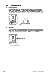
... checks the DRAM in any motherboard component. This is a reminder that lights up to the error device will continue lighting until the problem is ON, in sleep mode, or in soft-off mode. P8H67-M LX SB_PWR ON OFF Standby Power Powered Off P8H67-M LX Onboard LED 2. If an ... power LED that you should shut down the system and unplug the power cable before removing or plugging in sequence during motherboard booting process. P8H67-M LX DRAM LED P8H67-M LX DRAM LED 1-18 Chapter 1: Product introduction This user-friendly design provides an intuitional way to locate the root problem within...
... checks the DRAM in any motherboard component. This is a reminder that lights up to the error device will continue lighting until the problem is ON, in sleep mode, or in soft-off mode. P8H67-M LX SB_PWR ON OFF Standby Power Powered Off P8H67-M LX Onboard LED 2. If an ... power LED that you should shut down the system and unplug the power cable before removing or plugging in sequence during motherboard booting process. P8H67-M LX DRAM LED P8H67-M LX DRAM LED 1-18 Chapter 1: Product introduction This user-friendly design provides an intuitional way to locate the root problem within...
User Manual
Page 29
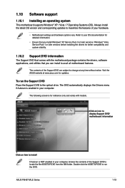
... screen is for updates. Click an icon to display Support DVD/ motherboard information Click an item to install If Autorun is enabled in your computer. Double-click the ASSETUP.EXE to the optical drive. ASUS P8H67-M LE Series 1-19 Visit the ASUS website at any time without notice. To run the Support DVD Place...
... screen is for updates. Click an icon to display Support DVD/ motherboard information Click an item to install If Autorun is enabled in your computer. Double-click the ASSETUP.EXE to the optical drive. ASUS P8H67-M LE Series 1-19 Visit the ASUS website at any time without notice. To run the Support DVD Place...
User Manual
Page 30
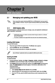
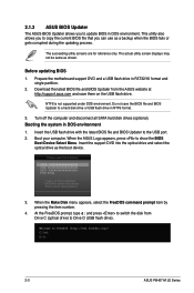
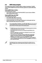
...FTP site, select the BIOS version that comes with the motherboard package. Follow the onscreen instructions to launch the AI Suite II utility. Quit all Windows® applications before you to download then click Next. 2-1 ASUS P8H67-M LE Series The AI Suite II Quick Bar appears. 2....the optical drive. Select the ASUS FTP site nearest you update the BIOS using the ASUS Update utility. 2.1.1 ASUS Update utility The ASUS Update is a utility that allows you to manage, save, and update the motherboard BIOS in Windows® environment. • ASUS Update requires an Internet connection ...
...FTP site, select the BIOS version that comes with the motherboard package. Follow the onscreen instructions to launch the AI Suite II utility. Quit all Windows® applications before you to download then click Next. 2-1 ASUS P8H67-M LE Series The AI Suite II Quick Bar appears. 2....the optical drive. Select the ASUS FTP site nearest you update the BIOS using the ASUS Update utility. 2.1.1 ASUS Update utility The ASUS Update is a utility that allows you to manage, save, and update the motherboard BIOS in Windows® environment. • ASUS Update requires an Internet connection ...
User Manual
Page 31
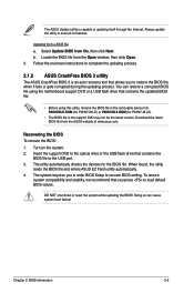
...the updating process. 2.1.2 ASUS CrashFree BIOS 3 utility The ASUS CrashFree BIOS 3 is capable of updating itself through the Internet. Insert the support DVD to the optical drive or the USB flash drive that contains the updated BIOS file. • Before using the motherboard support DVD or a ...on the system. 2. When found, the utility reads the BIOS file and enters ASUS EZ Flash utility automatically. 4. Always update the utility to recover BIOS setting. The utility automatically checks the devices for P8H67-M LX). • The BIOS file in the support DVD may not be the latest version...
...the updating process. 2.1.2 ASUS CrashFree BIOS 3 utility The ASUS CrashFree BIOS 3 is capable of updating itself through the Internet. Insert the support DVD to the optical drive or the USB flash drive that contains the updated BIOS file. • Before using the motherboard support DVD or a ...on the system. 2. When found, the utility reads the BIOS file and enters ASUS EZ Flash utility automatically. 4. Always update the utility to recover BIOS setting. The utility automatically checks the devices for P8H67-M LX). • The BIOS file in the support DVD may not be the latest version...
User Manual
Page 32
... Updater The ASUS BIOS Updater allows you can use as a backup when the BIOS fails or gets corrupted during the updating process. The actual utility screen displays may not be same as the boot device. Prepare the motherboard support DVD and a USB flash drive in ...DOS environment 1. Download the latest BIOS file and BIOS Updater from Drive C (optical drive) to boot using defaults 3. Booting the system in FAT32/16 format and single partition. 2. When the ASUS Logo appears, press to the USB port. 2. C:\>d: D:\> 2-3 ASUS P8H67...
... Updater The ASUS BIOS Updater allows you can use as a backup when the BIOS fails or gets corrupted during the updating process. The actual utility screen displays may not be same as the boot device. Prepare the motherboard support DVD and a USB flash drive in ...DOS environment 1. Download the latest BIOS file and BIOS Updater from Drive C (optical drive) to boot using defaults 3. Booting the system in FAT32/16 format and single partition. 2. When the ASUS Logo appears, press to the USB port. 2. C:\>d: D:\> 2-3 ASUS P8H67...
User Manual
Page 35
... any BIOS setting, load the default settings to ensure system compatibility and stability. The BIOS screens vary with its parameters. Chapter 2: BIOS information 2-6 ASUS P8H67-M LE Series motherboards include P8H67-M LE and P8H67-M LX two models. Using the power button, reset button, or the ++ keys to force reset from the operating system. • The BIOS setup...
... any BIOS setting, load the default settings to ensure system compatibility and stability. The BIOS screens vary with its parameters. Chapter 2: BIOS information 2-6 ASUS P8H67-M LE Series motherboards include P8H67-M LE and P8H67-M LX two models. Using the power button, reset button, or the ++ keys to force reset from the operating system. • The BIOS setup...
User Manual
Page 36
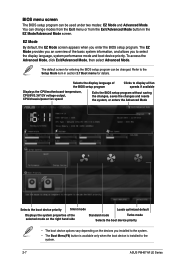
...devices you installed to the system. • The Boot Menu(F8) button is available only when the boot device is installed to the system. 2-7 ASUS P8H67-M LE Series You can change modes from the Exit menu or from the Exit/Advanced Mode button in section 2.7 Boot memu for entering the BIOS...mode and boot device priority. Selects the display language of the BIOS setup program Clicks to display all fan speeds if available Displays the CPU/motherboard temperature, CPU/5V/3.3V/12V voltage output, CPU/chassis/power fan speed Exits the BIOS setup program without saving the changes, saves the ...
...devices you installed to the system. • The Boot Menu(F8) button is available only when the boot device is installed to the system. 2-7 ASUS P8H67-M LE Series You can change modes from the Exit menu or from the Exit/Advanced Mode button in section 2.7 Boot memu for entering the BIOS...mode and boot device priority. Selects the display language of the BIOS setup program Clicks to display all fan speeds if available Displays the CPU/motherboard temperature, CPU/5V/3.3V/12V voltage output, CPU/chassis/power fan speed Exits the BIOS setup program without saving the changes, saves the ...
User Manual
Page 40
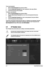
...prompted. From the Create New Password box, key in a password, then press . 3. The configuration options for this section vary depending on the motherboard. To change a user password: 1. EFI BIOS Utility - Advanced Mode Exit Main Ai Tweaker Advanced Monitor Memory Frequency Auto > GPU Boost > ...the Create New Password box, key in a new password, then press . 4. Confirm the password when prompted. To set a user password: 1. ASUS P8H67-M LE Series Select the User Password item and press . 2. After you clear the password, the User Password item on top of the Ai ...
...prompted. From the Create New Password box, key in a password, then press . 3. The configuration options for this section vary depending on the motherboard. To change a user password: 1. EFI BIOS Utility - Advanced Mode Exit Main Ai Tweaker Advanced Monitor Memory Frequency Auto > GPU Boost > ...the Create New Password box, key in a new password, then press . 4. Confirm the password when prompted. To set a user password: 1. ASUS P8H67-M LE Series Select the User Password item and press . 2. After you clear the password, the User Password item on top of the Ai ...


