
User Manual
Page 9
... 32GB memory capacity can be supported with DIMMs of 4GB capacity or more, Windows® 32-bit operating system may only recognize less than 3GB. ASUS will update the memory QVL once the DIMMs are using a Windows® 32-bit operating system. 1 x PCI Express x16 slot 1 x PCI Express x4 slot 2 x PCI... Definition Audio CODEC For P8H67M LE: - 2 x USB 3.0/2.0 ports (blue, at the back I/O) - 12 x USB 2.0/1.1 ports (8 ports at mid-board, 4 ports at the back panel) For P8H67-M LX: - 14 x USB 2.0/1.1 ports (8 ports at mid-board, 6 ports at the back panel) (continued on the next page) ix
... 32GB memory capacity can be supported with DIMMs of 4GB capacity or more, Windows® 32-bit operating system may only recognize less than 3GB. ASUS will update the memory QVL once the DIMMs are using a Windows® 32-bit operating system. 1 x PCI Express x16 slot 1 x PCI Express x4 slot 2 x PCI... Definition Audio CODEC For P8H67M LE: - 2 x USB 3.0/2.0 ports (blue, at the back I/O) - 12 x USB 2.0/1.1 ports (8 ports at mid-board, 4 ports at the back panel) For P8H67-M LX: - 14 x USB 2.0/1.1 ports (8 ports at mid-board, 6 ports at the back panel) (continued on the next page) ix
User Manual
Page 10
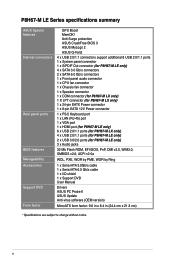
Anti-Surge protection ASUS CrashFree BIOS 3 ASUS MyLogo 2 ASUS Q-Fan2 4 x USB 2.0/1.1 connectors support additional 8 USB 2.0/1.1 ports 1 x System panel connector 1 x S/PDIF Out connector (for P8H67-M LE only) 4 x SATA 3.0 Gb/s connectors 2 x SATA 6.0 Gb/s connectors 1 x Front panel audio connector 1 x CPU fan connector 1 x Chassis fan connector 1 x Speaker connector 1 x COM connector (for P8H67-M LX only) 1 X LPT connector (for P8H67-M LX only) 1 x 24-pin EATX...
Anti-Surge protection ASUS CrashFree BIOS 3 ASUS MyLogo 2 ASUS Q-Fan2 4 x USB 2.0/1.1 connectors support additional 8 USB 2.0/1.1 ports 1 x System panel connector 1 x S/PDIF Out connector (for P8H67-M LE only) 4 x SATA 3.0 Gb/s connectors 2 x SATA 6.0 Gb/s connectors 1 x Front panel audio connector 1 x CPU fan connector 1 x Chassis fan connector 1 x Speaker connector 1 x COM connector (for P8H67-M LX only) 1 X LPT connector (for P8H67-M LX only) 1 x 24-pin EATX...
User Manual
Page 13
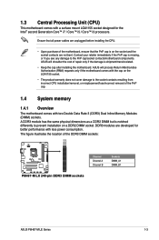
...socket and the socket contacts are developed for the Intel® second Generation Core™ i7 / Core™ i5 / Core™ i3 processors. ASUS will process Return Merchandise Authorization (RMA) requests only if the motherboard comes with two Double Data Rate 3 (DDR3) Dual Inline Memory Modules (DIMM) ...the socket contacts resulting from incorrect CPU installation/removal, or misplacement/loss/incorrect removal of the DDR3 DIMM sockets: DIMM_A1 DIMM_B1 P8H67-M LX Channel Channel A Channel B Sockets DIMM_A1 DIMM_B1 P8H67-M LX 240-pin DDR3 DIMM sockets ASUS P8H67-M LE Series 1-3
...socket and the socket contacts are developed for the Intel® second Generation Core™ i7 / Core™ i5 / Core™ i3 processors. ASUS will process Return Merchandise Authorization (RMA) requests only if the motherboard comes with two Double Data Rate 3 (DDR3) Dual Inline Memory Modules (DIMM) ...the socket contacts resulting from incorrect CPU installation/removal, or misplacement/loss/incorrect removal of the DDR3 DIMM sockets: DIMM_A1 DIMM_B1 P8H67-M LX Channel Channel A Channel B Sockets DIMM_A1 DIMM_B1 P8H67-M LX 240-pin DDR3 DIMM sockets ASUS P8H67-M LE Series 1-3

User Manual
Page 21
... . • We recommend that complies with more power-consuming devices. EATX12V EATXPWR +12V DC +12V DC +12V DC +12V DC P8H67-M LX GND GND GND GND +3 Volts +12 Volts +12 Volts +5V Standby Power OK PIN 1 GND +5 Volts GND +5 Volts GND +3 Volts +3 ...available for your system, refer to connect the 4-pin/8-pin ATX +12V power plug. 10. HDMI port (for details. USB 2.0 ports 5 and 6. ASUS P8H67-M LE Series 1-11 These two 4-pin Universal Serial Bus (USB) ports are uncertain about the minimum power supply requirement for connecting USB 2.0/1.1 devices. 1.7.2 Internal...
... . • We recommend that complies with more power-consuming devices. EATX12V EATXPWR +12V DC +12V DC +12V DC +12V DC P8H67-M LX GND GND GND GND +3 Volts +12 Volts +12 Volts +5V Standby Power OK PIN 1 GND +5 Volts GND +5 Volts GND +3 Volts +3 ...available for your system, refer to connect the 4-pin/8-pin ATX +12V power plug. 10. HDMI port (for details. USB 2.0 ports 5 and 6. ASUS P8H67-M LE Series 1-11 These two 4-pin Universal Serial Bus (USB) ports are uncertain about the minimum power supply requirement for connecting USB 2.0/1.1 devices. 1.7.2 Internal...
User Manual
Page 23
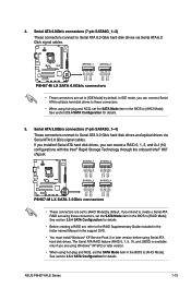
...hot-plug and NCQ, set the SATA Mode item in the BIOS to [RAID Mode]. See section 2.5.4 SATA Configuration for details. ASUS P8H67-M LE Series 1-13 See section 2.5.4 SATA Configuration for details. • Before creating a RAID set, refer to the RAID ...RSATA_TXP1 RSATA_TXN1 GND RSATA_RXP1 RSATA_RXN1 GND GND RSATA_TXP2 RSATA_TXN2 GND RSATA_RXP2 RSATA_RXN2 GND P8H67-M LX SATA3G_3 SATA3G_4 GND RSATA_TXP3 RSATA_TXN3 GND RSATA_RXP3 RSATA_RXN3 GND GND RSATA_TXP4 RSATA_TXN4 GND RSATA_RXP4 RSATA_RXN4 GND P8H67-M LX SATA 3.0Gb/s connectors • These connectors are set the SATA Mode...
...hot-plug and NCQ, set the SATA Mode item in the BIOS to [RAID Mode]. See section 2.5.4 SATA Configuration for details. ASUS P8H67-M LE Series 1-13 See section 2.5.4 SATA Configuration for details. • Before creating a RAID set, refer to the RAID ...RSATA_TXP1 RSATA_TXN1 GND RSATA_RXP1 RSATA_RXN1 GND GND RSATA_TXP2 RSATA_TXN2 GND RSATA_RXP2 RSATA_RXN2 GND P8H67-M LX SATA3G_3 SATA3G_4 GND RSATA_TXP3 RSATA_TXN3 GND RSATA_RXP3 RSATA_RXN3 GND GND RSATA_TXP4 RSATA_TXN4 GND RSATA_RXP4 RSATA_RXN4 GND P8H67-M LX SATA 3.0Gb/s connectors • These connectors are set the SATA Mode...

User Manual
Page 25
... GND SLIN# INIT# ERR# AFD SLCT PE BUSY ACK# PD7 PD6 PD5 PD4 PD3 PD2 PD1 PD0 STB# PIN 1 P8H67-M LX Parallel Port Connector ASUS P8H67-M LE Series 1-15 Ground Reset P8H67-M LX F_PANEL PIN 1 HD_LED RESET P8H67-M LX System panel connector • System power LED (2-pin PLED) This 2-pin connector is for the chassis-mounted reset button...
... GND SLIN# INIT# ERR# AFD SLCT PE BUSY ACK# PD7 PD6 PD5 PD4 PD3 PD2 PD1 PD0 STB# PIN 1 P8H67-M LX Parallel Port Connector ASUS P8H67-M LE Series 1-15 Ground Reset P8H67-M LX F_PANEL PIN 1 HD_LED RESET P8H67-M LX System panel connector • System power LED (2-pin PLED) This 2-pin connector is for the chassis-mounted reset button...
User Manual
Page 27
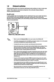
... lights continuously. This is ideal for overclockers and gamers who continually change settings to the latest BIOS version from the ASUS website at www.asus.com. • If you turn off the system and reinstall the DIMM before using the MemOK! switch •...the motherboard may cause system boot failure, and the DRAM_LED near the MemOK! ASUS P8H67-M LE Series 1-17 switch lights continuously. switch Installing DIMMs that you download and update to enhance system performance. P8H67-M LX P8H67-M LX MemOK! MemOK! 1.8 Onboard switches Onboard switches allow you to section 1.9 ...
... lights continuously. This is ideal for overclockers and gamers who continually change settings to the latest BIOS version from the ASUS website at www.asus.com. • If you turn off the system and reinstall the DIMM before using the MemOK! switch •...the motherboard may cause system boot failure, and the DRAM_LED near the MemOK! ASUS P8H67-M LE Series 1-17 switch lights continuously. switch Installing DIMMs that you download and update to enhance system performance. P8H67-M LX P8H67-M LX MemOK! MemOK! 1.8 Onboard switches Onboard switches allow you to section 1.9 ...
User Manual
Page 31
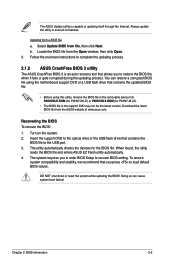
... drive that contains the updated BIOS file. • Before using this utility, rename the BIOS file in the removable device into P8H67MLE.ROM (for P8H67-M LE) or P8H67MLX.ROM (for the BIOS file. b. Chapter 2: BIOS information 2-2 Always update the utility to the USB port. 3. Follow ... BIOS file and enters ASUS EZ Flash utility automatically. 4. Download the latest BIOS file from a BIOS file a. Recovering the BIOS To recover the BIOS: 1. DO NOT shut down or reset the system while updating the BIOS! The utility automatically checks the devices for P8H67-M LX). • The BIOS...
... drive that contains the updated BIOS file. • Before using this utility, rename the BIOS file in the removable device into P8H67MLE.ROM (for P8H67-M LE) or P8H67MLX.ROM (for the BIOS file. b. Chapter 2: BIOS information 2-2 Always update the utility to the USB port. 3. Follow ... BIOS file and enters ASUS EZ Flash utility automatically. 4. Download the latest BIOS file from a BIOS file a. Recovering the BIOS To recover the BIOS: 1. DO NOT shut down or reset the system while updating the BIOS! The utility automatically checks the devices for P8H67-M LX). • The BIOS...
User Manual
Page 35
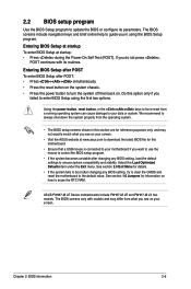
... down the system properly from the operating system. • The BIOS setup screens shown in using the first two options. ASUS P8H67-M LE Series motherboards include P8H67-M LE and P8H67-M LX two models. The BIOS screens vary with its parameters. The BIOS screens include navigation keys and brief online help to guide... Use the BIOS Setup program to update the BIOS or configure its routines. Entering BIOS Setup at startup To enter BIOS Setup at www.asus.com to download the latest BIOS file for this motherboard. • Ensure that a USB mouse is connected to enter BIOS Setup using ...
... down the system properly from the operating system. • The BIOS setup screens shown in using the first two options. ASUS P8H67-M LE Series motherboards include P8H67-M LE and P8H67-M LX two models. The BIOS screens vary with its parameters. The BIOS screens include navigation keys and brief online help to guide... Use the BIOS Setup program to update the BIOS or configure its routines. Entering BIOS Setup at startup To enter BIOS Setup at www.asus.com to download the latest BIOS file for this motherboard. • Ensure that a USB mouse is connected to enter BIOS Setup using ...

User Manual
Page 58
.... 6, 2010 EC Declaration of the following apparatus: Product name : Motherboard Model name : P8H67-M LX conform with part 15 of the FCC Rules. Address, City: No. 150, LI-TE RD., PEITOU, TAIPEI 112, TAIWAN R.O.C. Country: TAIWAN Authorized representative in Europe: ASUS COMPUTER GmbH Address, City: HARKORT STR. 21-23, 40880 RATINGEN Country: GERMANY declare...
.... 6, 2010 EC Declaration of the following apparatus: Product name : Motherboard Model name : P8H67-M LX conform with part 15 of the FCC Rules. Address, City: No. 150, LI-TE RD., PEITOU, TAIPEI 112, TAIWAN R.O.C. Country: TAIWAN Authorized representative in Europe: ASUS COMPUTER GmbH Address, City: HARKORT STR. 21-23, 40880 RATINGEN Country: GERMANY declare...


