User Manual
Page 15
... USB HDDs or flash drives, connect the drives to support.asus.com for Express Gate source codes. It is enhanced with the OpenGL standard. With such diversity of display outputs, you quick access to the Internet. Gigabit LAN solution The onboard LAN controller is a highly integrated Gb LAN controller. 1.3.2 Serial ATA 3Gb/s technology This motherboard supports hard drives based on the Serial ATA (SATA) 3Gb/s storage specifications, delivering enhanced salability and doubling the bus bandwidth for high-speed data saving and retrieval. 8-channel high...
... USB HDDs or flash drives, connect the drives to support.asus.com for Express Gate source codes. It is enhanced with the OpenGL standard. With such diversity of display outputs, you quick access to the Internet. Gigabit LAN solution The onboard LAN controller is a highly integrated Gb LAN controller. 1.3.2 Serial ATA 3Gb/s technology This motherboard supports hard drives based on the Serial ATA (SATA) 3Gb/s storage specifications, delivering enhanced salability and doubling the bus bandwidth for high-speed data saving and retrieval. 8-channel high...
User Manual
Page 16
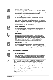
... update the BIOS from switching power supply unit (PSU). ASUS CrashFree BIOS 3 ASUS CrashFree BIOS 3 is an auto-recovery tool that allows you to restore a corrupted BIOS file using the bundled support DVD or a USB flash disk that detects the current system loadings and adjusts the power consumption in Hybrid CrossFireX™ mode. ASUS Anti-Surge Protection This special design prevents expensive devices and the motherboard from damage caused by power surges from a USB flash disk before entering the OS. ASUS...
... update the BIOS from switching power supply unit (PSU). ASUS CrashFree BIOS 3 ASUS CrashFree BIOS 3 is an auto-recovery tool that allows you to restore a corrupted BIOS file using the bundled support DVD or a USB flash disk that detects the current system loadings and adjusts the power consumption in Hybrid CrossFireX™ mode. ASUS Anti-Surge Protection This special design prevents expensive devices and the motherboard from damage caused by power surges from a USB flash disk before entering the OS. ASUS...
User Manual
Page 19
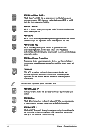
...slots 5. LPT connector (26-1 pin LPT) 7. IDE connector (40-1 pin PRI_IDE) Page Connectors/Jumpers/Slots/LED 1-29 8. SATA connectors (7-pin SATA1-6) 1-25 1-8 10. USB connectors (10-1 pin USB78, USB910, 1-27 USB1112) 1-29 13. Serial port connector (10-1 pin COM1) 6. Onboard power LED (SB_PWR) 1-27 12. Digital audio connector (4-1 pin SPDIF_OUT) 1-28 1-24 14. Front panel audio connector (10-1 pin AAFP) 1-28 ASUS M4A785-M 1-7 CPU and chassis fan connectors (4-pin CPU_FAN and 3-pin CHA_FAN) 2. Clear RTC RAM (3-pin CLRTC) Page 1-19 1-23 9. 1.5.3 Motherboard layout...
...slots 5. LPT connector (26-1 pin LPT) 7. IDE connector (40-1 pin PRI_IDE) Page Connectors/Jumpers/Slots/LED 1-29 8. SATA connectors (7-pin SATA1-6) 1-25 1-8 10. USB connectors (10-1 pin USB78, USB910, 1-27 USB1112) 1-29 13. Serial port connector (10-1 pin COM1) 6. Onboard power LED (SB_PWR) 1-27 12. Digital audio connector (4-1 pin SPDIF_OUT) 1-28 1-24 14. Front panel audio connector (10-1 pin AAFP) 1-28 ASUS M4A785-M 1-7 CPU and chassis fan connectors (4-pin CPU_FAN and 3-pin CHA_FAN) 2. Clear RTC RAM (3-pin CLRTC) Page 1-19 1-23 9. 1.5.3 Motherboard layout...
User Manual
Page 30
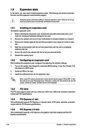
.... Unplug the power cord before adding or removing expansion cards. Failure to use . 4. Otherwise, conflicts will arise between the two PCI groups, making the system unstable and the card inoperable. 1.8.3 PCI slots The PCI slots support cards such as a LAN card, SCSI card, USB card, and other cards that comply with PCI specifications. 1.8.4 PCI Express x1 slot This motherboard supports PCI Express x1 network cards, SCSI cards, and other cards that comply with the PCI Express specifications. 1.8.5 PCI Express x16 slot This motherboard supports a PCI Express x16 graphics card that came with...
.... Unplug the power cord before adding or removing expansion cards. Failure to use . 4. Otherwise, conflicts will arise between the two PCI groups, making the system unstable and the card inoperable. 1.8.3 PCI slots The PCI slots support cards such as a LAN card, SCSI card, USB card, and other cards that comply with PCI specifications. 1.8.4 PCI Express x1 slot This motherboard supports PCI Express x1 network cards, SCSI cards, and other cards that comply with the PCI Express specifications. 1.8.5 PCI Express x16 slot This motherboard supports a PCI Express x16 graphics card that came with...
User Manual
Page 33
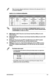
... audio device of sound playback is HDCP compliant allowing playback of HD DVD, Blu-ray, and other protected content. 14. These two 4-pin Universal Serial Bus (USB) ports are for a High-Definition Multimedia Interface (HDMI) connector, and is VIA High Definition Audio (the name may be different based on your motherboard: Dual display outputs DVI + D-Sub DVI + HDMI HDMI + D-Sub Supported • • Not supported • • During POST, only the monitor connected to configure...
... audio device of sound playback is HDCP compliant allowing playback of HD DVD, Blu-ray, and other protected content. 14. These two 4-pin Universal Serial Bus (USB) ports are for a High-Definition Multimedia Interface (HDMI) connector, and is VIA High Definition Audio (the name may be different based on your motherboard: Dual display outputs DVI + D-Sub DVI + HDMI HDMI + D-Sub Supported • • Not supported • • During POST, only the monitor connected to configure...
User Manual
Page 37
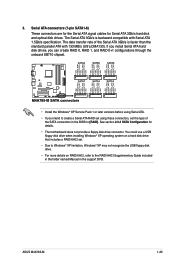
... RAID 0, RAID 1, and RAID 0+1 configurations through the onboard SB710 chipset. • Install the Windows® XP Service Pack 1 or later versions before using Serial ATA. • If you intend to create a Serial ATA RAID set using these connectors, set . • Due to Windows® XP limitation, Windows® XP may not recognize the USB floppy disk drive. • For more details on RAID/AHCI, refer to the RAID/AHCI Supplementary Guide included in the folder named Manual in the BIOS to [RAID...
... RAID 0, RAID 1, and RAID 0+1 configurations through the onboard SB710 chipset. • Install the Windows® XP Service Pack 1 or later versions before using Serial ATA. • If you intend to create a Serial ATA RAID set using these connectors, set . • Due to Windows® XP limitation, Windows® XP may not recognize the USB floppy disk drive. • For more details on RAID/AHCI, refer to the RAID/AHCI Supplementary Guide included in the folder named Manual in the BIOS to [RAID...
User Manual
Page 42
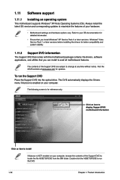
... that you install Windows® XP Service Pack 3 or later versions / Windows® Vista Service Pack 1 or later versions before installing the drivers for better compatibility and system stability. 1.11.2 Support DVD information The Support DVD that comes with the motherboard package contains the drivers, software applications, and utilities that you can install to change at www.asus.com for reference only. Always install the latest OS version and corresponding updates to maximize the...
... that you install Windows® XP Service Pack 3 or later versions / Windows® Vista Service Pack 1 or later versions before installing the drivers for better compatibility and system stability. 1.11.2 Support DVD information The Support DVD that comes with the motherboard package contains the drivers, software applications, and utilities that you can install to change at www.asus.com for reference only. Always install the latest OS version and corresponding updates to maximize the...
User Manual
Page 43
... the Windows® desktop, click Start > Programs > ASUS > ASUS Update > ASUS Update to complete the installation. Copy the original motherboard BIOS using this utility. Click the Utilities tab, then click ASUS Update. 3. Select Update BIOS from the Internet a. From the FTP site, select the BIOS version that you to manage, save, and update the motherboard BIOS in Windows® environment. • ASUS Update requires an Internet connection either of the original motherboard BIOS file to a USB flash disk in case you need to avoid network...
... the Windows® desktop, click Start > Programs > ASUS > ASUS Update > ASUS Update to complete the installation. Copy the original motherboard BIOS using this utility. Click the Utilities tab, then click ASUS Update. 3. Select Update BIOS from the Internet a. From the FTP site, select the BIOS version that you to manage, save, and update the motherboard BIOS in Windows® environment. • ASUS Update requires an Internet connection either of the original motherboard BIOS file to a USB flash disk in case you need to avoid network...
User Manual
Page 44
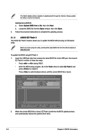
... Flash 2 BIOS ROM Utility V3.36 FLASH TYPE: WINBOND W25X80 Current ROM BOARD: M4A785-M VER: 0304 (H:00 B:02) DATE: 07/29/2009 Update ROM BOARD: Unknown VER: Unknown DATE: Unknown PATH: C:\ C: Note [Enter] Select or Load [Tab] Switch [Up/Down/Home/End] Move [B] Backup [V] Drive Info [ESC] Exit 2. Updating from a file, then click Next. b. Follow the onscreen instructions to complete the updating process. 2.1.2 ASUS EZ Flash 2 The ASUS EZ Flash 2 feature allows you start using EZ Flash 2: 1. Locate...
... Flash 2 BIOS ROM Utility V3.36 FLASH TYPE: WINBOND W25X80 Current ROM BOARD: M4A785-M VER: 0304 (H:00 B:02) DATE: 07/29/2009 Update ROM BOARD: Unknown VER: Unknown DATE: Unknown PATH: C:\ C: Note [Enter] Select or Load [Tab] Switch [Up/Down/Home/End] Move [B] Backup [V] Drive Info [ESC] Exit 2. Updating from a file, then click Next. b. Follow the onscreen instructions to complete the updating process. 2.1.2 ASUS EZ Flash 2 The ASUS EZ Flash 2 feature allows you start using EZ Flash 2: 1. Locate...
User Manual
Page 45
... supports USB flash disks with motherboard models. Download the latest BIOS file from the ASUS website at www.asus.com. • The removable devices that allows you to the floppy disk drive, if supported. 3. For motherboards without the floppy connector, prepare a USB flash disk before using the motherboard support DVD or a removable device that contains the BIOS file to the USB port or to restore the BIOS file when it fails or gets corrupted during the updating process. ASUS M4A785-M 2-3 You can cause system boot failure! Refer to ensure system compatibility...
... supports USB flash disks with motherboard models. Download the latest BIOS file from the ASUS website at www.asus.com. • The removable devices that allows you to the floppy disk drive, if supported. 3. For motherboards without the floppy connector, prepare a USB flash disk before using the motherboard support DVD or a removable device that contains the BIOS file to the USB port or to restore the BIOS file when it fails or gets corrupted during the updating process. ASUS M4A785-M 2-3 You can cause system boot failure! Refer to ensure system compatibility...
User Manual
Page 48
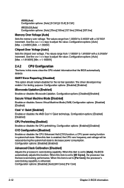
... CPU Configuration Module Version: 13.55 AGESA Version: 3.5.2.0 BIOS SETUP UTILITY AMD Phenom(tm) II X4 945 Processor Revision: C2 Cache L1: 512KB Cache L2: 2048KB Cache L3: 6MB Options Speed : 3000MHz, NB Cl Disabled Able to display a pop-up window Select a menu item then press to Change Freq.: Yes Enabled uCode Patch Level: 0x1 GART Error Reporting [Disabled] Microcode Updation [Enabled] Secure Virtual Machine Mode [Disabled] Cool 'n' Quiet [Enalbed] C1E Configuration [Disabled] Advanced Clock Calibration [Disabled] This option...
... CPU Configuration Module Version: 13.55 AGESA Version: 3.5.2.0 BIOS SETUP UTILITY AMD Phenom(tm) II X4 945 Processor Revision: C2 Cache L1: 512KB Cache L2: 2048KB Cache L3: 6MB Options Speed : 3000MHz, NB Cl Disabled Able to display a pop-up window Select a menu item then press to Change Freq.: Yes Enabled uCode Patch Level: 0x1 GART Error Reporting [Disabled] Microcode Updation [Enabled] Secure Virtual Machine Mode [Disabled] Cool 'n' Quiet [Enalbed] C1E Configuration [Disabled] Advanced Clock Calibration [Disabled] This option...
User Manual
Page 50
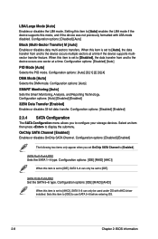
...to display the submenu. Sets this item to the device occurs multiple sectors at a time. Configuration options: [Auto] SMART Monitoring [Auto] Sets the Smart Monitoring, Analysis, and Reporting Technology. SATA Port1-Port4 [IDE] Sets the SATA 1~4 type. Setting this item to [IDE] to configure your storage devices. When this item is set OnChip SATA Channel to [Enabled]. Configuration options: [IDE] [RAID] [AHCI] When this item is set to [IDE], SATA 5~6 can only be set to [Auto], the data transfer from and to [IDE]. Configuration options: [Auto] [0] [1] [2] [3] [4] DMA Mode...
...to display the submenu. Sets this item to the device occurs multiple sectors at a time. Configuration options: [Auto] SMART Monitoring [Auto] Sets the Smart Monitoring, Analysis, and Reporting Technology. SATA Port1-Port4 [IDE] Sets the SATA 1~4 type. Setting this item to [IDE] to configure your storage devices. When this item is set OnChip SATA Channel to [Enabled]. Configuration options: [IDE] [RAID] [AHCI] When this item is set to [IDE], SATA 5~6 can only be set to [Auto], the data transfer from and to [IDE]. Configuration options: [Auto] [0] [1] [2] [3] [4] DMA Mode...
User Manual
Page 51
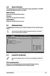
... Settings Power BIOS SETUP UTILITY Boot Tools Exit JumperFree Configuration CPU Configuration Chipset Onboard Devices Configuration PCIPnP USB Configuration Adjust System Frequency/Voltage etc. Change Field Tab Select Field F1 General Help F10 Save and Exit ESC Exit v02.61 (C)Copyright 1985-2009, American Megatrends, Inc. 2.4.1 JumperFree Configuration The items and configuration options in this menu may vary depending on the AMD CPU type. CPU Overclocking [Auto] Selects the CPU overclocking options to achieve desired CPU internal frequency. BIOS Information Displays the auto...
... Settings Power BIOS SETUP UTILITY Boot Tools Exit JumperFree Configuration CPU Configuration Chipset Onboard Devices Configuration PCIPnP USB Configuration Adjust System Frequency/Voltage etc. Change Field Tab Select Field F1 General Help F10 Save and Exit ESC Exit v02.61 (C)Copyright 1985-2009, American Megatrends, Inc. 2.4.1 JumperFree Configuration The items and configuration options in this menu may vary depending on the AMD CPU type. CPU Overclocking [Auto] Selects the CPU overclocking options to achieve desired CPU internal frequency. BIOS Information Displays the auto...
User Manual
Page 52
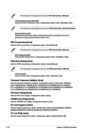
...Max.=150] Processor Frequency Multiplier [Auto] Sets the processor frequency multiplier. Configuration options: [Auto] VDDNB Over Voltage [Auto] Sets the VDDNB over voltage. The following item only appears when you set PCIE Overclocking to [Manual]. Configuration options: [Auto] [Manual] The following item only appears when you set CPU Overclocking to [Manual]. PCIE Clock [100] Sets the PCIE Clock. Overclock Options [Auto] Selects the overclocking profile. Configuration options: [Min.=150] [Max.=1500] PCIE Overclocking [Auto] Sets the PCIE overclocking. Configuration options...
...Max.=150] Processor Frequency Multiplier [Auto] Sets the processor frequency multiplier. Configuration options: [Auto] VDDNB Over Voltage [Auto] Sets the VDDNB over voltage. The following item only appears when you set PCIE Overclocking to [Manual]. Configuration options: [Auto] [Manual] The following item only appears when you set CPU Overclocking to [Manual]. PCIE Clock [100] Sets the PCIE Clock. Overclock Options [Auto] Selects the overclocking profile. Configuration options: [Min.=150] [Max.=1500] PCIE Overclocking [Auto] Sets the PCIE overclocking. Configuration options...
User Manual
Page 54
...] [Enabled] Advanced Clock Calibration [Disabled] Adjusts the processor's overclocking capability. When this menu show the CPU-related information that the BIOS automatically detects. Configuration options: [Auto] [Max. = 2.4450V] [Min. = 1.5000V] Chipset Over Voltage [Auto] Sets the chipset over voltage. Configuration options: [Enabled] [Disabled] C1E Configuration [Disabled] Enables or disables the CPU Enhanced Halt (C1E) function, a CPU power-saving function in this item is enhanced. Configuration options: [Disabled] [Enabled] Secure Virtual Machine Mode [Disabled] Enables or...
...] [Enabled] Advanced Clock Calibration [Disabled] Adjusts the processor's overclocking capability. When this menu show the CPU-related information that the BIOS automatically detects. Configuration options: [Auto] [Max. = 2.4450V] [Min. = 1.5000V] Chipset Over Voltage [Auto] Sets the chipset over voltage. Configuration options: [Enabled] [Disabled] C1E Configuration [Disabled] Enables or disables the CPU Enhanced Halt (C1E) function, a CPU power-saving function in this item is enhanced. Configuration options: [Disabled] [Enabled] Secure Virtual Machine Mode [Disabled] Enables or...
User Manual
Page 55
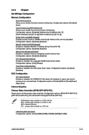
... Clocks to set the primary video controller. Configuration options: [Auto] [Always] Power Down Enable [Disabled] Enables or disables the DDR power down mode. Configuration options: [GFX0-GPP-IGFX-PCI] [GPP-GFX0-IGFX-PCI] [PCI-GFX0-GPP-IGFX] [IGFX-GFX0-GPP-PCI] GFX0:primary video controller on a PCIe x16 slot GPP: primary video controller on a PCIe x1 slot IGFX: onboard VGA port PCI: primary video controller on a PCI slot UMA Frame Buffer Size [Auto] Configuration options: [Auto] [32MB] [64MB] [128MB] [256MB] [512MB] ASUS M4A785-M 2-13 Configuration options: [Disabled] [Address bits...
... Clocks to set the primary video controller. Configuration options: [Auto] [Always] Power Down Enable [Disabled] Enables or disables the DDR power down mode. Configuration options: [GFX0-GPP-IGFX-PCI] [GPP-GFX0-IGFX-PCI] [PCI-GFX0-GPP-IGFX] [IGFX-GFX0-GPP-PCI] GFX0:primary video controller on a PCIe x16 slot GPP: primary video controller on a PCIe x1 slot IGFX: onboard VGA port PCI: primary video controller on a PCI slot UMA Frame Buffer Size [Auto] Configuration options: [Auto] [32MB] [64MB] [128MB] [256MB] [512MB] ASUS M4A785-M 2-13 Configuration options: [Disabled] [Address bits...
User Manual
Page 56
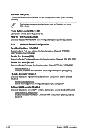
... Device Configuration Serial Port1 Address [3F8/IRQ4] Selects the Serial Port1 base address. Configuration options: [Disabled] [378] [278] [3BC] Parallel Port Mode [Normal] Selects the Parallel Port mode. Configuration options: [Normal] [EPP] [ECP] [EPP+ECP] Parallel Port IRQ [IRQ7] Allows BIOS to select the Parallel Port IRQ. Configuration options: [Auto] [Disabled] [Enabled] This item becomes user-configurable when you install an ATI graphics card into the PCIe x16 slot. Configuration options: [Enabled] [Disabled] OnBoard LAN Boot ROM [Disabled] Enables or disables the Onboard LAN Boot...
... Device Configuration Serial Port1 Address [3F8/IRQ4] Selects the Serial Port1 base address. Configuration options: [Disabled] [378] [278] [3BC] Parallel Port Mode [Normal] Selects the Parallel Port mode. Configuration options: [Normal] [EPP] [ECP] [EPP+ECP] Parallel Port IRQ [IRQ7] Allows BIOS to select the Parallel Port IRQ. Configuration options: [Auto] [Disabled] [Enabled] This item becomes user-configurable when you install an ATI graphics card into the PCIe x16 slot. Configuration options: [Enabled] [Disabled] OnBoard LAN Boot ROM [Disabled] Enables or disables the Onboard LAN Boot...
User Manual
Page 57
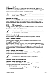
... legacy mode is set to [No], BIOS configures all the devices in this item is enabled. Select an item then press to initialize. Configuration options: [Disabled] [Enabled] USB 2.0 Controller [Enabled] Enables or disables the USB 2.0 controller. 2.4.5 PCIPnP The PCI PnP menu items allow you to set the emulation type. Take caution when changing the settings of USB devices at startup. USB Mass Storage Device Configuration USB Mass Storage Reset Delay [20 Sec] Sets the maximum time that the BIOS waits for boot. Configuration options: [Auto] [Floppy] [Forced FDD] [Hard Disk...
... legacy mode is set to [No], BIOS configures all the devices in this item is enabled. Select an item then press to initialize. Configuration options: [Disabled] [Enabled] USB 2.0 Controller [Enabled] Enables or disables the USB 2.0 controller. 2.4.5 PCIPnP The PCI PnP menu items allow you to set the emulation type. Take caution when changing the settings of USB devices at startup. USB Mass Storage Device Configuration USB Mass Storage Reset Delay [20 Sec] Sets the maximum time that the BIOS waits for boot. Configuration options: [Auto] [Floppy] [Forced FDD] [Hard Disk...
User Manual
Page 58
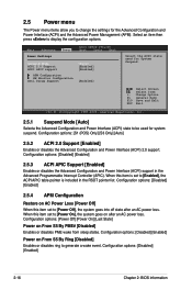
...event. Main Advanced Power Settings Power BIOS SETUP UTILITY Boot Tools Exit Suspend Mode [Auto] ACPI 2.0 Support [Enabled] ACPI APIC support [Enabled] APM Configuration HW Monitor Configuration Anti Surgy Support [Enabled] Select the ACPI state used for System Suspend. When this item is included in the Advanced Programmable Interrupt Controller (APIC). Configuration options: [Disabled] [Enabled] 2-16 Chapter 2: BIOS information 2.5 Power menu The Power menu items allow you to display the configuration options. Configuration options: [Disabled] [Enabled] Power on...
...event. Main Advanced Power Settings Power BIOS SETUP UTILITY Boot Tools Exit Suspend Mode [Auto] ACPI 2.0 Support [Enabled] ACPI APIC support [Enabled] APM Configuration HW Monitor Configuration Anti Surgy Support [Enabled] Select the ACPI state used for System Suspend. When this item is included in the Advanced Programmable Interrupt Controller (APIC). Configuration options: [Disabled] [Enabled] 2-16 Chapter 2: BIOS information 2.5 Power menu The Power menu items allow you to display the configuration options. Configuration options: [Disabled] [Enabled] Power on...
User Manual
Page 60
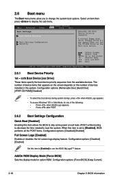
... the screen depends on self tests (POST) while booting to decrease the time needed to change the system boot options. 2.6 Boot menu The Boot menu items allow you set to display the sub-menu. Configuration options: [Removable Dev.] [Hard Drive] [ATAPI CD-ROM] [Disabled] • To select the boot device during system startup, press when ASUS Logo appears. • To access Windows® OS in the system. Main Advanced Power Boot Settings Boot Device Priority BIOS SETUP UTILITY Boot Tools Exit Boot Settings Configuration Security Specifies the Boot Device Priority...
... the screen depends on self tests (POST) while booting to decrease the time needed to change the system boot options. 2.6 Boot menu The Boot menu items allow you set to display the sub-menu. Configuration options: [Removable Dev.] [Hard Drive] [ATAPI CD-ROM] [Disabled] • To select the boot device during system startup, press when ASUS Logo appears. • To access Windows® OS in the system. Main Advanced Power Boot Settings Boot Device Priority BIOS SETUP UTILITY Boot Tools Exit Boot Settings Configuration Security Specifies the Boot Device Priority...


