User Manual
Page 3
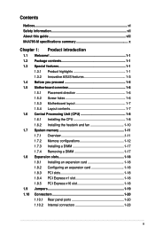
Contents Notices...vi Safety information vii About this guide viii M4A785-M specifications summary x Chapter 1: Product introduction 1.1 Welcome 1-1 1.2 Package contents 1-1 1.3 Special features 1-1 1.3.1 Product highlights 1-1 1.3.2 Innovative ASUS features 1-3 1.4 Before you proceed 1-5 1.5 Motherboard overview 1-6 1.5.1 Placement direction 1-6 1.5.2 Screw holes 1-6 1.5.3 Motherboard layout 1-7 1.5.4 Layout contents 1-7 1.6 Central Processing Unit ...x1 slot 1-18 1.8.5 PCI Express x16 slot 1-18 1.9 Jumpers 1-19 1.10 Connectors 1-20 1.10.1 Rear panel ports 1-20 1.10.2 Internal...
Contents Notices...vi Safety information vii About this guide viii M4A785-M specifications summary x Chapter 1: Product introduction 1.1 Welcome 1-1 1.2 Package contents 1-1 1.3 Special features 1-1 1.3.1 Product highlights 1-1 1.3.2 Innovative ASUS features 1-3 1.4 Before you proceed 1-5 1.5 Motherboard overview 1-6 1.5.1 Placement direction 1-6 1.5.2 Screw holes 1-6 1.5.3 Motherboard layout 1-7 1.5.4 Layout contents 1-7 1.6 Central Processing Unit ...x1 slot 1-18 1.8.5 PCI Express x16 slot 1-18 1.9 Jumpers 1-19 1.10 Connectors 1-20 1.10.1 Rear panel ports 1-20 1.10.2 Internal...

User Manual
Page 11
... - M4A785-M specifications summary Storage Audio USB LAN ASUS unique features ASUS overclocking features Back panel I/O ports 1 x Ultra DMA 133/100/66 connector for up to 12 USB 2.0/1.1 ports (6 ports at mid-board, 6 ports at the back panel) Realtek® 8112L PCIe Gigabit LAN controller ASUS 4+1 Phase Power Design ASUS EPU-4 Engine ASUS Express Gate ASUS Turbo Key ASUS Anti-Surge ASUS CrashFree...
... - M4A785-M specifications summary Storage Audio USB LAN ASUS unique features ASUS overclocking features Back panel I/O ports 1 x Ultra DMA 133/100/66 connector for up to 12 USB 2.0/1.1 ports (6 ports at mid-board, 6 ports at the back panel) Realtek® 8112L PCIe Gigabit LAN controller ASUS 4+1 Phase Power Design ASUS EPU-4 Engine ASUS Express Gate ASUS Turbo Key ASUS Anti-Surge ASUS CrashFree...
User Manual
Page 12
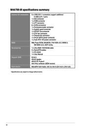
M4A785-M specifications summary Internal I/O connectors BIOS Accessories Support DVD Form factor 3 x USB 2.0/1.1 connectors support additional 6 USB 2.0/1.1 ports 1 x IDE connector 1 x COM connector 1 x LPT connector 6 x SATA connectors 1 x Front panel audio connector 1 x System panel connector 1 x S/PDIF Out connector 1 x CPU fan connector 1 x Chassis fan connector 1 x 24-pin EATX power connector 1 x 4-pin ATX 12V power connector 8Mb Flash ROM, AMI BIOS, PnP, DMI v2.0, WfM2.0, SM BIOS v2.5, ACPI v2.0a, 1 x Ultra DMA...
M4A785-M specifications summary Internal I/O connectors BIOS Accessories Support DVD Form factor 3 x USB 2.0/1.1 connectors support additional 6 USB 2.0/1.1 ports 1 x IDE connector 1 x COM connector 1 x LPT connector 6 x SATA connectors 1 x Front panel audio connector 1 x System panel connector 1 x S/PDIF Out connector 1 x CPU fan connector 1 x Chassis fan connector 1 x 24-pin EATX power connector 1 x 4-pin ATX 12V power connector 8Mb Flash ROM, AMI BIOS, PnP, DMI v2.0, WfM2.0, SM BIOS v2.5, ACPI v2.0a, 1 x Ultra DMA...
User Manual
Page 19
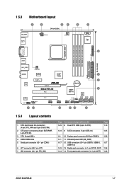
...) 7. System panel connector (20-8 pin PANEL) 1-26 1-11 11. Onboard power LED (SB_PWR) 1-27 12. Front panel audio connector (10-1 pin AAFP) 1-28 ASUS M4A785-M 1-7 DDR2 DIMM slots 5. CPU and chassis fan connectors (4-pin CPU_FAN and 3-pin CHA_FAN) 2. Clear RTC RAM (3-pin CLRTC) Page 1-19 1-23 9. CPU Socket AM2+ 4. Serial port connector (10-1 pin COM1) 6. 1.5.3 Motherboard layout 1.5.4 Layout contents Connectors/Jumpers...
...) 7. System panel connector (20-8 pin PANEL) 1-26 1-11 11. Onboard power LED (SB_PWR) 1-27 12. Front panel audio connector (10-1 pin AAFP) 1-28 ASUS M4A785-M 1-7 DDR2 DIMM slots 5. CPU and chassis fan connectors (4-pin CPU_FAN and 3-pin CHA_FAN) 2. Clear RTC RAM (3-pin CLRTC) Page 1-19 1-23 9. CPU Socket AM2+ 4. Serial port connector (10-1 pin COM1) 6. 1.5.3 Motherboard layout 1.5.4 Layout contents Connectors/Jumpers...

User Manual
Page 32
..., DVD player, or other VGA-compatible devices. 4. This port connects to the center/subwoofer speakers. 6. Center/Subwoofer port (orange). Microphone port (pink). 1.10 1.10.1 Connectors Rear panel ports 1. Optical S/PDIF_OUT port. VGA port. This port connects to the rear speakers in the 8-channel audio configuration. 1-20 Chapter 1: Product introduction Line Out port...
..., DVD player, or other VGA-compatible devices. 4. This port connects to the center/subwoofer speakers. 6. Center/Subwoofer port (orange). Microphone port (pink). 1.10 1.10.1 Connectors Rear panel ports 1. Optical S/PDIF_OUT port. VGA port. This port connects to the rear speakers in the 8-channel audio configuration. 1-20 Chapter 1: Product introduction Line Out port...
User Manual
Page 33
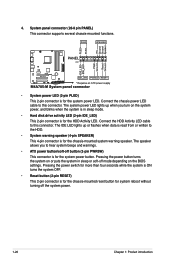
... content. This port is for the function of sound playback is VIA High Definition Audio (the name may be different based on your motherboard: Dual display outputs DVI + D-Sub DVI + HDMI HDMI + D-Sub Supported • • Not supported • •...channel configuration. Go to Start > Control Panel > Sounds and Audio Devices > Sound Playback to the audio configuration table below for a High-Definition Multimedia Interface (HDMI) connector, and is HDCP compliant allowing playback of HD DVD, Blu-ray, and other protected content. 14. ASUS M4A785-M 1-21 HDMI port. Audio 2, ...
... content. This port is for the function of sound playback is VIA High Definition Audio (the name may be different based on your motherboard: Dual display outputs DVI + D-Sub DVI + HDMI HDMI + D-Sub Supported • • Not supported • •...channel configuration. Go to Start > Control Panel > Sounds and Audio Devices > Sound Playback to the audio configuration table below for a High-Definition Multimedia Interface (HDMI) connector, and is HDCP compliant allowing playback of HD DVD, Blu-ray, and other protected content. 14. ASUS M4A785-M 1-21 HDMI port. Audio 2, ...
User Manual
Page 38
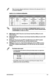
... Hard disk drive activity LED (2-pin IDE_LED) This 2-pin connector is for the system power button. System panel connector (20-8 pin PANEL) This connector supports several chassis-mounted functions. • System power LED (2-pin PLED) This 2-pin connector is for the chassis-mounted reset button for system reboot without... power LED lights up or flashes when data is read from or written to this connector. Connect the HDD Activity LED cable to hear system beeps and warnings. • ATX power button/soft-off the system power. 1-26 Chapter 1: Product introduction Pressing the power...
... Hard disk drive activity LED (2-pin IDE_LED) This 2-pin connector is for the system power button. System panel connector (20-8 pin PANEL) This connector supports several chassis-mounted functions. • System power LED (2-pin PLED) This 2-pin connector is for the chassis-mounted reset button for system reboot without... power LED lights up or flashes when data is read from or written to this connector. Connect the HDD Activity LED cable to hear system beeps and warnings. • ATX power button/soft-off the system power. 1-26 Chapter 1: Product introduction Pressing the power...
User Manual
Page 40
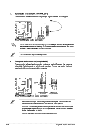
... AC`97 audio standard. Front panel audio connector (10-1 pin AAFP) This connector is for details. • The front panel audio I /O module cable to this connector. • We recommend that the audio device of the motherboard high-definition audio capability. • If you connect a high-definition front panel audio module to this connector to avail of Sound playback...
... AC`97 audio standard. Front panel audio connector (10-1 pin AAFP) This connector is for details. • The front panel audio I /O module cable to this connector. • We recommend that the audio device of the motherboard high-definition audio capability. • If you connect a high-definition front panel audio module to this connector to avail of Sound playback...


