User Manual
Page 19
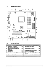
... (20-8 pin PANEL) 1-26 1-11 11. Digital audio connector (4-1 pin SPDIF_OUT) 1-28 1-24 14. Clear RTC RAM (3-pin CLRTC) Page 1-19 1-23 9. ATX power connectors (24-pin EATXPWR, 4-pin ATX12V) 3. LPT connector (26-1 pin LPT) 7. DDR2 DIMM slots 5. CPU...Motherboard layout 1.5.4 Layout contents Connectors/Jumpers/Slots/LED 1. IDE connector (40-1 pin PRI_IDE) Page Connectors/Jumpers/Slots/LED 1-29 8. SATA connectors (7-pin SATA1-6) 1-25 1-8 10. USB connectors (10-1 pin USB78, USB910, 1-27 USB1112) 1-29 13. Front panel audio connector (10-1 pin AAFP) 1-28 ASUS M4A785...
... (20-8 pin PANEL) 1-26 1-11 11. Digital audio connector (4-1 pin SPDIF_OUT) 1-28 1-24 14. Clear RTC RAM (3-pin CLRTC) Page 1-19 1-23 9. ATX power connectors (24-pin EATXPWR, 4-pin ATX12V) 3. LPT connector (26-1 pin LPT) 7. DDR2 DIMM slots 5. CPU...Motherboard layout 1.5.4 Layout contents Connectors/Jumpers/Slots/LED 1. IDE connector (40-1 pin PRI_IDE) Page Connectors/Jumpers/Slots/LED 1-29 8. SATA connectors (7-pin SATA1-6) 1-25 1-8 10. USB connectors (10-1 pin USB78, USB910, 1-27 USB1112) 1-29 13. Front panel audio connector (10-1 pin AAFP) 1-28 ASUS M4A785...
User Manual
Page 31
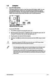
...system setup parameters by erasing the CMOS RTC RAM data. After clearing the CMOS, reinstall the battery. • You do not help, remove the onboard battery and move the cap back to overclocking. For system failure due to pins 2-3. ASUS M4A785-M 1-19 Keep the cap on CLRTC jumper ...default position. 1.9 Jumpers 1. The onboard button cell battery powers the RAM data in CMOS. Plug the power cord and turn ON the computer. 4. Shut...
...system setup parameters by erasing the CMOS RTC RAM data. After clearing the CMOS, reinstall the battery. • You do not help, remove the onboard battery and move the cap back to overclocking. For system failure due to pins 2-3. ASUS M4A785-M 1-19 Keep the cap on CLRTC jumper ...default position. 1.9 Jumpers 1. The onboard button cell battery powers the RAM data in CMOS. Plug the power cord and turn ON the computer. 4. Shut...

User Manual
Page 61
..., follow the same steps as Date and Time. Full Access allows viewing and changing all the fields in a password containing up to erase the RTC RAM. Configuration options: [Disabled] [Enabled] Hit 'DEL' Message Display [Enabled] When this item to be pressed when error occurs. Configuration options: [Disabled]...password. Bootup Num-Lock [On] Selects the power-on state for 'F1' If Error [Enabled] When this item shows Installed. ASUS M4A785-M 2-19 The message Password uninstalled appears. Configuration options: [Off] [On] Wait for the NumLock. Confirm the password when prompted.
..., follow the same steps as Date and Time. Full Access allows viewing and changing all the fields in a password containing up to erase the RTC RAM. Configuration options: [Disabled] [Enabled] Hit 'DEL' Message Display [Enabled] When this item to be pressed when error occurs. Configuration options: [Disabled]...password. Bootup Num-Lock [On] Selects the power-on state for 'F1' If Error [Enabled] When this item shows Installed. ASUS M4A785-M 2-19 The message Password uninstalled appears. Configuration options: [Off] [On] Wait for the NumLock. Confirm the password when prompted.

User Manual
Page 64
...fields other changes before exiting. If you made to the Setup program. Select OK to the non-volatile RAM. 2-22 Chapter 2: BIOS information Select Exit & Save Changes or make other than System Date, System ...select this option, a confirmation appears. Select+FFEEFFEo-11Sn11Sn0Ct0CeeorSSCGSEf eeheaxtSSGGSEhllanvieeoeaxeeeneetllnviccgroeeteettteaapccorlntttaaioSIOdSlnnctpHSIudsreteEctbHemilxfre-eEreopioemslxnntmecpinrtteheisn Once you are saved to the CMOS RAM. Discard Changes This option allows you to load default values. After selecting this option, a confirmation window appears...
...fields other changes before exiting. If you made to the Setup program. Select OK to the non-volatile RAM. 2-22 Chapter 2: BIOS information Select Exit & Save Changes or make other than System Date, System ...select this option, a confirmation appears. Select+FFEEFFEo-11Sn11Sn0Ct0CeeorSSCGSEf eeheaxtSSGGSEhllanvieeoeaxeeeneetllnviccgroeeteettteaapccorlntttaaioSIOdSlnnctpHSIudsreteEctbHemilxfre-eEreopioemslxnntmecpinrtteheisn Once you are saved to the CMOS RAM. Discard Changes This option allows you to load default values. After selecting this option, a confirmation window appears...


