User Manual
Page 4
... 1.11.1 Installing an operating system 1-30 1.11.2 Support DVD information 1-30 Chapter 2: BIOS information 2.1 Managing and updating your BIOS 2-1 2.1.1 ASUS Update utility 2-1 2.1.2 ASUS EZ Flash 2 2-2 2.1.3 ASUS CrashFree BIOS 2-3 2.2 BIOS setup program 2-4 2.2.1 BIOS menu screen 2-5 2.2.2 Menu bar 2-5 2.2.3 Navigation keys 2-5 2.2.4 Menu items 2-6 2.2.5 ... 2-9 2.4.2 CPU Configuration 2-12 2.4.3 Chipset 2-13 2.4.4 Onboard Device Configuration 2-14 2.4.5 PCIPnP 2-15 2.4.6 USB Configuration 2-15 2.5 Power menu 2-16 2.5.1 Suspend Mode 2-16 2.5.2 ACPI 2.0 Support 2-16 iv
... 1.11.1 Installing an operating system 1-30 1.11.2 Support DVD information 1-30 Chapter 2: BIOS information 2.1 Managing and updating your BIOS 2-1 2.1.1 ASUS Update utility 2-1 2.1.2 ASUS EZ Flash 2 2-2 2.1.3 ASUS CrashFree BIOS 2-3 2.2 BIOS setup program 2-4 2.2.1 BIOS menu screen 2-5 2.2.2 Menu bar 2-5 2.2.3 Navigation keys 2-5 2.2.4 Menu items 2-6 2.2.5 ... 2-9 2.4.2 CPU Configuration 2-12 2.4.3 Chipset 2-13 2.4.4 Onboard Device Configuration 2-14 2.4.5 PCIPnP 2-15 2.4.6 USB Configuration 2-15 2.5 Power menu 2-16 2.5.1 Suspend Mode 2-16 2.5.2 ACPI 2.0 Support 2-16 iv

User Manual
Page 7
...S/PDIF is an optional component (may or may not be included in your motherboard) and is set to the correct voltage in fire. vii It could interrupt the grounding circuit. • Ensure that your power supply is defined as a CLASS 1 LASER PRODUCT. These devices could explode ...; Never dispose of the electrical outlet you add a device. • Before connecting or removing signal cables from the motherboard, ensure that all power cables from the system, ensure that the power cables for the devices are unplugged before the signal cables are using an adapter or extension cord.
...S/PDIF is an optional component (may or may not be included in your motherboard) and is set to the correct voltage in fire. vii It could interrupt the grounding circuit. • Ensure that your power supply is defined as a CLASS 1 LASER PRODUCT. These devices could explode ...; Never dispose of the electrical outlet you add a device. • Before connecting or removing signal cables from the motherboard, ensure that all power cables from the system, ensure that the power cables for the devices are unplugged before the signal cables are using an adapter or extension cord.
User Manual
Page 8
..., and temperature extremes. How this guide This user guide contains the information you need when installing and configuring the motherboard. Detailed descriptions of the motherboard and the new technology it may become wet. viii About this guide is organized This guide contains the following parts... safety • Before installing the motherboard and adding devices on a stable surface. • If you encounter technical problems with the package. • Before using the product, ensure that all cables are correctly connected and the power cables are also provided. If you...
..., and temperature extremes. How this guide This user guide contains the information you need when installing and configuring the motherboard. Detailed descriptions of the motherboard and the new technology it may become wet. viii About this guide is organized This guide contains the following parts... safety • Before installing the motherboard and adding devices on a stable surface. • If you encounter technical problems with the package. • Before using the product, ensure that all cables are correctly connected and the power cables are also provided. If you...

User Manual
Page 11
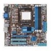
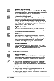
... RAID 1, RAID 0+1, and JBOD configurations VIA® VT1708S 8-channel High Definition Audio CODEC - M4A785-M specifications summary Storage Audio USB LAN ASUS unique features ASUS overclocking features Back panel I /O - FSB tuning from 100MHz up to 150MHz at 1MHz increment Overclocking ...the back panel) Realtek® 8112L PCIe Gigabit LAN controller ASUS 4+1 Phase Power Design ASUS EPU-4 Engine ASUS Express Gate ASUS Turbo Key ASUS Anti-Surge ASUS CrashFree BIOS 3 ASUS EZ Flash 2 ASUS Q-Fan ASUS MyLogo 2 ASUS AI NET 2 Intelligent overclocking tools: - Supports Jack-detection, ...
... RAID 1, RAID 0+1, and JBOD configurations VIA® VT1708S 8-channel High Definition Audio CODEC - M4A785-M specifications summary Storage Audio USB LAN ASUS unique features ASUS overclocking features Back panel I /O - FSB tuning from 100MHz up to 150MHz at 1MHz increment Overclocking ...the back panel) Realtek® 8112L PCIe Gigabit LAN controller ASUS 4+1 Phase Power Design ASUS EPU-4 Engine ASUS Express Gate ASUS Turbo Key ASUS Anti-Surge ASUS CrashFree BIOS 3 ASUS EZ Flash 2 ASUS Q-Fan ASUS MyLogo 2 ASUS AI NET 2 Intelligent overclocking tools: - Supports Jack-detection, ...
User Manual
Page 12
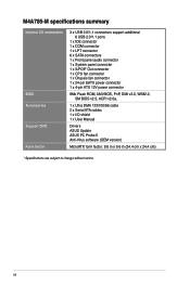
... fan connector 1 x Chassis fan connector 1 x 24-pin EATX power connector 1 x 4-pin ATX 12V power connector 8Mb Flash ROM, AMI BIOS, PnP, DMI v2.0, WfM2.0, SM BIOS v2.5, ACPI v2.0a, 1 x Ultra DMA 133/100/66 cable 2 x Serial ATA cables 1 x I/O shield 1 x User Manual Drivers ASUS Update ASUS PC Probe II Anti-Virus software (OEM version) MicroATX...
... fan connector 1 x Chassis fan connector 1 x 24-pin EATX power connector 1 x 4-pin ATX 12V power connector 8Mb Flash ROM, AMI BIOS, PnP, DMI v2.0, WfM2.0, SM BIOS v2.5, ACPI v2.0a, 1 x Ultra DMA 133/100/66 cable 2 x Serial ATA cables 1 x I/O shield 1 x User Manual Drivers ASUS Update ASUS PC Probe II Anti-Virus software (OEM version) MicroATX...
User Manual
Page 13
... motherboard delivers a host of the above items is damaged or missing, contact your retailer. 1.3 1.3.1 Special features Product highlights AMD® Phenom™ II / Athlon™II / Sempron™ 100 Series processors This motherboard supports AMD® AM3 multi-core processors with unique L3 cache and delivers better overclocking capabilities with less power consumption. ASUS M4A785...
... motherboard delivers a host of the above items is damaged or missing, contact your retailer. 1.3 1.3.1 Special features Product highlights AMD® Phenom™ II / Athlon™II / Sempron™ 100 Series processors This motherboard supports AMD® AM3 multi-core processors with unique L3 cache and delivers better overclocking capabilities with less power consumption. ASUS M4A785...
User Manual
Page 15
... This motherboard supports multiple digital and analog display output interfaces: HDMI, DVI, and D-Sub. Five seconds after powering on your computer, you quick access to provide efficient power management for Express Gate source codes. Refer to choose and upgrade display devices freely. It is enhanced with at least 1.2GB free disk space. ASUS M4A785-M 1-3 With...
... This motherboard supports multiple digital and analog display output interfaces: HDMI, DVI, and D-Sub. Five seconds after powering on your computer, you quick access to provide efficient power management for Express Gate source codes. Refer to choose and upgrade display devices freely. It is enhanced with at least 1.2GB free disk space. ASUS M4A785-M 1-3 With...
User Manual
Page 16
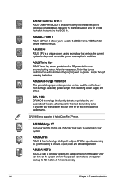
... that detects the current system loadings and adjusts the power consumption in Hybrid CrossFireX™ mode. ASUS Q-Fan ASUS Q-Fan technology intelligently adjusts CPU fan speeds according to system loading to personalize your system. ASUS AI NET 2 ASUS AI NET 2 remotely detects the cable connection immediately ... work or games, simply through pressing the button. GPU NOS is not supported in real time. ASUS Anti-Surge Protection This special design prevents expensive devices and the motherboard from damage caused by power surges from a USB flash disk before entering the OS.
... that detects the current system loadings and adjusts the power consumption in Hybrid CrossFireX™ mode. ASUS Q-Fan ASUS Q-Fan technology intelligently adjusts CPU fan speeds according to system loading to personalize your system. ASUS AI NET 2 ASUS AI NET 2 remotely detects the cable connection immediately ... work or games, simply through pressing the button. GPU NOS is not supported in real time. ASUS Anti-Surge Protection This special design prevents expensive devices and the motherboard from damage caused by power surges from a USB flash disk before entering the OS.
User Manual
Page 17
...you should shut down and reboot the system, and the BIOS automatically restores the CPU parameters to overclocking failure. ASUS M4A785-M 1-5 Green ASUS This motherboard and its power cord. feature automatically restores the CPU default settings when the system hangs due to their default settings. This is... ON, in sleep mode, or in soft-off the ATX power supply and detach its packaging comply with the European Union...
...you should shut down and reboot the system, and the BIOS automatically restores the CPU parameters to overclocking failure. ASUS M4A785-M 1-5 Green ASUS This motherboard and its power cord. feature automatically restores the CPU default settings when the system hangs due to their default settings. This is... ON, in sleep mode, or in soft-off the ATX power supply and detach its packaging comply with the European Union...
User Manual
Page 19
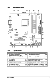
Front panel audio connector (10-1 pin AAFP) 1-28 ASUS M4A785-M 1-7 CPU Socket AM2+ 4. LPT connector (26-1 pin LPT) 7. System panel connector (20-8 pin PANEL) 1-26 1-11 11. CPU and chassis fan connectors (4-pin CPU_FAN and...port connector (10-1 pin COM1) 6. Clear RTC RAM (3-pin CLRTC) Page 1-19 1-23 9. DDR2 DIMM slots 5. SATA connectors (7-pin SATA1-6) 1-25 1-8 10. Onboard power LED (SB_PWR) 1-27 12. ATX power connectors (24-pin EATXPWR, 4-pin ATX12V) 3. USB connectors (10-1 pin USB78, USB910, 1-27 USB1112) 1-29 13. IDE connector (40-1 pin PRI_IDE) Page Connectors...
Front panel audio connector (10-1 pin AAFP) 1-28 ASUS M4A785-M 1-7 CPU Socket AM2+ 4. LPT connector (26-1 pin LPT) 7. System panel connector (20-8 pin PANEL) 1-26 1-11 11. CPU and chassis fan connectors (4-pin CPU_FAN and...port connector (10-1 pin COM1) 6. Clear RTC RAM (3-pin CLRTC) Page 1-19 1-23 9. DDR2 DIMM slots 5. SATA connectors (7-pin SATA1-6) 1-25 1-8 10. Onboard power LED (SB_PWR) 1-27 12. ATX power connectors (24-pin EATXPWR, 4-pin ATX12V) 3. USB connectors (10-1 pin USB78, USB910, 1-27 USB1112) 1-29 13. IDE connector (40-1 pin PRI_IDE) Page Connectors...
User Manual
Page 29
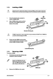
... outward to avoid damaging the DIMM. 3. 1.7.3 Installing a DIMM Unplug the power supply before adding or removing DIMMs or other system components. Firmly insert the...the break on the socket. 2 DIMM notch 1 1 Unlocked retaining clip A DIMM is properly seated. DIMM notch ASUS M4A785-M 1-17 Align a DIMM on the socket such that it flips out with your fingers when pressing the retaining ...Removing a DIMM To remove a DIMM: 1. Press the retaining clips outward to both the motherboard and the components. 1. Failure to do so can cause severe damage to unlock a DIMM socket. 2. Remove...
... outward to avoid damaging the DIMM. 3. 1.7.3 Installing a DIMM Unplug the power supply before adding or removing DIMMs or other system components. Firmly insert the...the break on the socket. 2 DIMM notch 1 1 Unlocked retaining clip A DIMM is properly seated. DIMM notch ASUS M4A785-M 1-17 Align a DIMM on the socket such that it flips out with your fingers when pressing the retaining ...Removing a DIMM To remove a DIMM: 1. Press the retaining clips outward to both the motherboard and the components. 1. Failure to do so can cause severe damage to unlock a DIMM socket. 2. Remove...
User Manual
Page 30
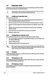
... you physical injury and damage motherboard components. 1.8.1 Installing an expansion card To install an expansion card: 1. The following sub‑sections describe the slots and the expansion cards that you removed earlier. 6. Turn on BIOS setup. 2. Unplug the power cord before adding or removing ...expansion cards. Remove the system unit cover (if your motherboard is completely seated on shared slots, ensure that the drivers support "Share IRQ" or that...
... you physical injury and damage motherboard components. 1.8.1 Installing an expansion card To install an expansion card: 1. The following sub‑sections describe the slots and the expansion cards that you removed earlier. 6. Turn on BIOS setup. 2. Unplug the power cord before adding or removing ...expansion cards. Remove the system unit cover (if your motherboard is completely seated on shared slots, ensure that the drivers support "Share IRQ" or that...
User Manual
Page 31
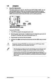
... the Real Time Clock (RTC) RAM in CMOS, which include system setup information such as system passwords. Turn OFF the computer and unplug the power cord. 2. ASUS M4A785-M 1-19 Hold down and reboot the system so the BIOS can clear the CMOS memory of date, time, and system setup parameters by erasing... do not need to clear the RTC when the system hangs due to reenter data. Keep the cap on CLRTC jumper default position. Plug the power cord and turn ON the computer. 4. After clearing the CMOS, reinstall the battery. • You do not help, remove the onboard battery and ...
... the Real Time Clock (RTC) RAM in CMOS, which include system setup information such as system passwords. Turn OFF the computer and unplug the power cord. 2. ASUS M4A785-M 1-19 Hold down and reboot the system so the BIOS can clear the CMOS memory of date, time, and system setup parameters by erasing... do not need to clear the RTC when the system hangs due to reenter data. Keep the cap on CLRTC jumper default position. Plug the power cord and turn ON the computer. 4. After clearing the CMOS, reinstall the battery. • You do not help, remove the onboard battery and ...
User Manual
Page 35
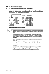
..., refer to connect the 4-pin ATX +12V power plug. com/PowerSupplyCalculator/PSCalculator.aspx?SLanguage=en-us for an ATX power supply. Otherwise, the system will not boot up. • We recommend that the PSU has a minimum power rating of 300W power rating. ASUS M4A785-M 1-23 1.10.2 Internal connectors 1. The plugs from the power supply are for details. Find the...
..., refer to connect the 4-pin ATX +12V power plug. com/PowerSupplyCalculator/PSCalculator.aspx?SLanguage=en-us for an ATX power supply. Otherwise, the system will not boot up. • We recommend that the PSU has a minimum power rating of 300W power rating. ASUS M4A785-M 1-23 1.10.2 Internal connectors 1. The plugs from the power supply are for details. Find the...
User Manual
Page 38
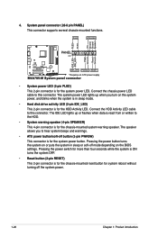
... lights up or flashes when data is read from or written to hear system beeps and warnings. • ATX power button/soft-off button (2-pin PWRSW) This connector is for the HDD Activity LED. Connect the HDD Activity LED cable to this connector. The IDE... on or puts the system in sleep mode. • Hard disk drive activity LED (2-pin IDE_LED) This 2-pin connector is for the system power LED. Pressing the power switch for the chassis-mounted system warning speaker. System panel connector (20-8 pin PANEL) This connector supports several chassis-mounted functions. • System...
... lights up or flashes when data is read from or written to hear system beeps and warnings. • ATX power button/soft-off button (2-pin PWRSW) This connector is for the HDD Activity LED. Connect the HDD Activity LED cable to this connector. The IDE... on or puts the system in sleep mode. • Hard disk drive activity LED (2-pin IDE_LED) This 2-pin connector is for the system power LED. Pressing the power switch for the chassis-mounted system warning speaker. System panel connector (20-8 pin PANEL) This connector supports several chassis-mounted functions. • System...
User Manual
Page 46
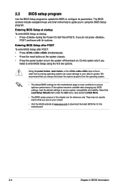
...properly from a running operating system can cause damage to force reset from the operating system. • The default BIOS settings for this motherboard. 2-4 Chapter 2: BIOS information They may not exactly match what you do not press , POST continues with its parameters. Entering BIOS Setup...BIOS file for reference only. Using the power button, reset button, or the ++ keys to your screen. • Visit the ASUS website at startup: • Press during the Power-On Self Test (POST). Do this chapter are for this motherboard apply to most conditions to ensure optimum ...
...properly from a running operating system can cause damage to force reset from the operating system. • The default BIOS settings for this motherboard. 2-4 Chapter 2: BIOS information They may not exactly match what you do not press , POST continues with its parameters. Entering BIOS Setup...BIOS file for reference only. Using the power button, reset button, or the ++ keys to your screen. • Visit the ASUS website at startup: • Press during the Power-On Self Test (POST). Do this chapter are for this motherboard apply to most conditions to ensure optimum ...
User Manual
Page 47
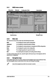
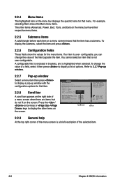
2.2.1 BIOS menu screen Menu items Menu bar Configuration fields Main Advanced Power BIOS SETUP UTILITY Boot Tools Exit Main Settings System Time [19:34:30] System Date [Thu 01/03/2002] Primary IDE... For changing the basic system configuration Advanced For changing the advanced system settings Power For changing the advanced power management (APM) configuration Boot For changing the system boot configuration Tools For configuring options for that particular menu. ASUS M4A785-M 2-5 Some of a menu screen are the navigation keys for special functions...
2.2.1 BIOS menu screen Menu items Menu bar Configuration fields Main Advanced Power BIOS SETUP UTILITY Boot Tools Exit Main Settings System Time [19:34:30] System Date [Thu 01/03/2002] Primary IDE... For changing the basic system configuration Advanced For changing the advanced system settings Power For changing the advanced power management (APM) configuration Boot For changing the system boot configuration Tools For configuring options for that particular menu. ASUS M4A785-M 2-5 Some of a menu screen are the navigation keys for special functions...
User Manual
Page 48
... item that the item has a submenu. Refer to 2.2.7 Pop-up window. 2.2.7 Pop-up window Select a menu item then press to display the other items (Advanced, Power, Boot, Tools, and Exit) on the menu bar have their respective menu items. 2.2.5 Submenu items A solid triangle before each item on the screen. Select Screen...
... item that the item has a submenu. Refer to 2.2.7 Pop-up window. 2.2.7 Pop-up window Select a menu item then press to display the other items (Advanced, Power, Boot, Tools, and Exit) on the menu bar have their respective menu items. 2.2.5 Submenu items A solid triangle before each item on the screen. Select Screen...
User Manual
Page 49
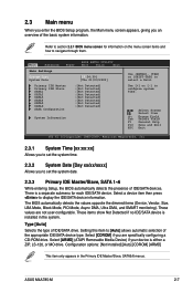
...configure system Time. These items show Not Detected if no IDE/SATA device is either a ZIP, LS-120, or MO drive. Main Advanced Power BIOS SETUP UTILITY Boot Tools Exit Main Settings System Time [19:34:30] System Date [Thu 01/03/2002] Primary IDE Master Primary ...] :[Not Detected] :[Not Detected] System Information Use [ENTER], [TAB] or [SHIFT-TAB] to section 2.2.1 BIOS menu screen for each IDE/SATA device. ASUS M4A785-M 2-7 Select [CDROM] if you to navigate through them. There is a separate submenu for information on the menu screen items and how to set the system...
...configure system Time. These items show Not Detected if no IDE/SATA device is either a ZIP, LS-120, or MO drive. Main Advanced Power BIOS SETUP UTILITY Boot Tools Exit Main Settings System Time [19:34:30] System Date [Thu 01/03/2002] Primary IDE Master Primary ...] :[Not Detected] :[Not Detected] System Information Use [ENTER], [TAB] or [SHIFT-TAB] to section 2.2.1 BIOS menu screen for each IDE/SATA device. ASUS M4A785-M 2-7 Select [CDROM] if you to navigate through them. There is a separate submenu for information on the menu screen items and how to set the system...
User Manual
Page 51
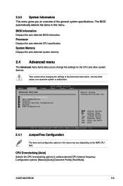
...in this menu may vary depending on the AMD CPU type. Configuration options: [Manual] [Auto] [Overclock Profile] [Test Mode] ASUS M4A785-M 2-9 The BIOS automatically detects the items in this menu. Processor Displays the auto-detected CPU specification. System Memory Displays the auto...menu items. Incorrect field values can cause the system to achieve desired CPU internal frequency. Main Advanced Advanced Settings Power BIOS SETUP UTILITY Boot Tools Exit JumperFree Configuration CPU Configuration Chipset Onboard Devices Configuration PCIPnP USB Configuration Adjust System Frequency...
...in this menu may vary depending on the AMD CPU type. Configuration options: [Manual] [Auto] [Overclock Profile] [Test Mode] ASUS M4A785-M 2-9 The BIOS automatically detects the items in this menu. Processor Displays the auto-detected CPU specification. System Memory Displays the auto...menu items. Incorrect field values can cause the system to achieve desired CPU internal frequency. Main Advanced Advanced Settings Power BIOS SETUP UTILITY Boot Tools Exit JumperFree Configuration CPU Configuration Chipset Onboard Devices Configuration PCIPnP USB Configuration Adjust System Frequency...


