
User Manual
Page 1
M4A785-M Motherboard
M4A785-M Motherboard
User Manual
Page 3
Contents Notices...vi Safety information vii About this guide viii M4A785-M specifications summary x Chapter 1: Product introduction 1.1 Welcome 1-1 1.2 Package contents 1-1 1.3 Special features 1-1 1.3.1 Product highlights 1-1 1.3.2 Innovative ASUS features 1-3 1.4 Before you proceed 1-5 1.5 Motherboard overview 1-6 1.5.1 Placement direction 1-6 1.5.2 Screw holes 1-6 1.5.3 Motherboard layout 1-7 1.5.4 Layout contents 1-7 1.6 Central Processing Unit (CPU 1-8 1.6.1 Installing the CPU 1-8 1.6.2 Installing the heatsink and fan 1-10 1.7 System memory 1-11...
Contents Notices...vi Safety information vii About this guide viii M4A785-M specifications summary x Chapter 1: Product introduction 1.1 Welcome 1-1 1.2 Package contents 1-1 1.3 Special features 1-1 1.3.1 Product highlights 1-1 1.3.2 Innovative ASUS features 1-3 1.4 Before you proceed 1-5 1.5 Motherboard overview 1-6 1.5.1 Placement direction 1-6 1.5.2 Screw holes 1-6 1.5.3 Motherboard layout 1-7 1.5.4 Layout contents 1-7 1.6 Central Processing Unit (CPU 1-8 1.6.1 Installing the CPU 1-8 1.6.2 Installing the heatsink and fan 1-10 1.7 System memory 1-11...
User Manual
Page 6
... Class B digital device, pursuant to radio communications. These limits are designed to assure compliance with FCC regulations. DO NOT throw the motherboard in municipal waste. Check local regulations for radio noise emissions from that to the following two conditions: • This device may not ...This device complies with Part 15 of Chemicals) regulatory framework, we published the chemical substances in our products at ASUS REACH website at http://green.asus.com/english/REACH.htm. Operation is no guarantee that the product (electrical and electronic equipment) should not be ...
... Class B digital device, pursuant to radio communications. These limits are designed to assure compliance with FCC regulations. DO NOT throw the motherboard in municipal waste. Check local regulations for radio noise emissions from that to the following two conditions: • This device may not ...This device complies with Part 15 of Chemicals) regulatory framework, we published the chemical substances in our products at ASUS REACH website at http://green.asus.com/english/REACH.htm. Operation is no guarantee that the product (electrical and electronic equipment) should not be ...

User Manual
Page 7
INVISIBLE LASER RADIATION, AVOID EXPOSURE TO BEAM. • Never dispose of the battery in your motherboard) and is broken, do not try to a hazardous material collection point. • Never replace the battery with your regular household waste. If possible, disconnect ... ACCORDING TO THE ABOVE BATTERY-RELATED INSTRUCTIONS. Contact a qualified service technician or your retailer. • The optical S/PDIF is set to or from the motherboard, ensure that the power cables for the devices are unplugged before the signal cables are connected. Take it to fix it by yourself. It could...
INVISIBLE LASER RADIATION, AVOID EXPOSURE TO BEAM. • Never dispose of the battery in your motherboard) and is broken, do not try to a hazardous material collection point. • Never replace the battery with your regular household waste. If possible, disconnect ... ACCORDING TO THE ABOVE BATTERY-RELATED INSTRUCTIONS. Contact a qualified service technician or your retailer. • The optical S/PDIF is set to or from the motherboard, ensure that the power cables for the devices are unplugged before the signal cables are connected. Take it to fix it by yourself. It could...
User Manual
Page 8
... are correctly connected and the power cables are also provided. If you need when installing and configuring the motherboard. viii Operation safety • Before installing the motherboard and adding devices on a stable surface. • If you encounter technical problems with the package. &#...slots, sockets and circuitry. • Avoid dust, humidity, and temperature extremes. Detailed descriptions of the motherboard and the new technology it may become wet. This motherboard should only be used in any damage, contact your retailer. About this guide is organized This guide...
... are correctly connected and the power cables are also provided. If you need when installing and configuring the motherboard. viii Operation safety • Before installing the motherboard and adding devices on a stable surface. • If you encounter technical problems with the package. &#...slots, sockets and circuitry. • Avoid dust, humidity, and temperature extremes. Detailed descriptions of the motherboard and the new technology it may become wet. This motherboard should only be used in any damage, contact your retailer. About this guide is organized This guide...
User Manual
Page 13
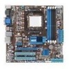
... above items is damaged or missing, contact your motherboard package for buying an ASUS® M4A785-M motherboard! Thank you start installing the motherboard, and hardware devices on it another standout in the new 45nm manufacturing process. ASUS M4A785-M 1-1 Before you for the following items. Motherboard Cables Accessories Application DVD Documentations ASUS M4A785-M motherboard 2 x Serial ATA cables 1 x Ultra DMA 133/100/66...
... above items is damaged or missing, contact your motherboard package for buying an ASUS® M4A785-M motherboard! Thank you start installing the motherboard, and hardware devices on it another standout in the new 45nm manufacturing process. ASUS M4A785-M 1-1 Before you for the following items. Motherboard Cables Accessories Application DVD Documentations ASUS M4A785-M motherboard 2 x Serial ATA cables 1 x Ultra DMA 133/100/66...
User Manual
Page 14
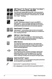
...3.0 technology provides 2.6 times more bandwidth to provide excellent system performance and overclocking capabilities. AMD Cool 'n' Quiet Technology This motherboard supports the AMD Cool 'n' Quiet technology which monitors system operation and automatically adjusts CPU voltage and frequency for the discrete ...Phenom™ X4 / Phenom™ X3 / Athlon™ X2 / Athlon™ / Sempron™ processors (socket AM2+/AM2) This motherboard supports AMD® Socket AM2+ multi-core processors. The S/PDIF transfers digital audio without converting it to 5200MT/s HyperTransport™ 3.0 (...
...3.0 technology provides 2.6 times more bandwidth to provide excellent system performance and overclocking capabilities. AMD Cool 'n' Quiet Technology This motherboard supports the AMD Cool 'n' Quiet technology which monitors system operation and automatically adjusts CPU voltage and frequency for the discrete ...Phenom™ X4 / Phenom™ X3 / Athlon™ X2 / Athlon™ / Sempron™ processors (socket AM2+/AM2) This motherboard supports AMD® Socket AM2+ multi-core processors. The S/PDIF transfers digital audio without converting it to 5200MT/s HyperTransport™ 3.0 (...
User Manual
Page 15
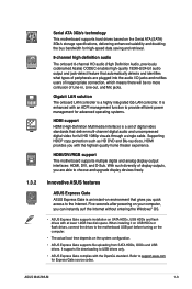
... supports file uploading from SATA HDDs, ODDs and USB drives. ASUS M4A785-M 1-3 It is enhanced with an ACPI management function to provide efficient power management for full HD 1080p visuals through a single cable. With such diversity of peripherals are able to the motherboard USB port before turning on the computer. • The actual...
... supports file uploading from SATA HDDs, ODDs and USB drives. ASUS M4A785-M 1-3 It is enhanced with an ACPI management function to provide efficient power management for full HD 1080p visuals through a single cable. With such diversity of peripherals are able to the motherboard USB port before turning on the computer. • The actual...
User Manual
Page 16
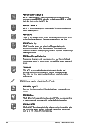
...to update the BIOS from switching power supply unit (PSU). ASUS EPU ASUS EPU is a unique power saving technology that contains the BIOS file. ASUS Anti-Surge Protection This special design prevents expensive devices and the motherboard from damage caused by power surges from a USB flash ...disk before entering the OS. ASUS EZ Flash 2 ASUS EZ Flash 2 allows you with a faster reaction ...
...to update the BIOS from switching power supply unit (PSU). ASUS EPU ASUS EPU is a unique power saving technology that contains the BIOS file. ASUS Anti-Surge Protection This special design prevents expensive devices and the motherboard from damage caused by power surges from a USB flash ...disk before entering the OS. ASUS EZ Flash 2 ASUS EZ Flash 2 allows you with a faster reaction ...
User Manual
Page 17
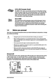
... system chassis and clear the RTC data. ASUS M4A785-M 1-5 The illustration below shows the location of Hazardous Substances (RoHS). Simply shut down the system and unplug the power cable before touching any motherboard component. Green ASUS This motherboard and its power cord. This is ON,..., or components. Onboard LED The motherboard comes with the ASUS vision of creating environment-friendly and recyclable products/packaging to safeguard consumers' health while minimizing the impact on a grounded antistatic pad or in soft-off the ATX power supply and detach its packaging ...
... system chassis and clear the RTC data. ASUS M4A785-M 1-5 The illustration below shows the location of Hazardous Substances (RoHS). Simply shut down the system and unplug the power cable before touching any motherboard component. Green ASUS This motherboard and its power cord. This is ON,..., or components. Onboard LED The motherboard comes with the ASUS vision of creating environment-friendly and recyclable products/packaging to safeguard consumers' health while minimizing the impact on a grounded antistatic pad or in soft-off the ATX power supply and detach its packaging ...

User Manual
Page 18
Doing so can damage the motherboard. Place this side towards the rear of the chassis as indicated in the image below. 1.5.2 Screw holes Place eight screws into the chassis in the correct orientation. DO NOT overtighten the screws! 1.5 Motherboard overview 1.5.1 Placement direction When installing the motherboard, ensure that you place it into the holes indicated by circles to secure the motherboard to the chassis. The edge with external ports goes to the rear part of the chassis. 1-6 Chapter 1: Product introduction
Doing so can damage the motherboard. Place this side towards the rear of the chassis as indicated in the image below. 1.5.2 Screw holes Place eight screws into the chassis in the correct orientation. DO NOT overtighten the screws! 1.5 Motherboard overview 1.5.1 Placement direction When installing the motherboard, ensure that you place it into the holes indicated by circles to secure the motherboard to the chassis. The edge with external ports goes to the rear part of the chassis. 1-6 Chapter 1: Product introduction
User Manual
Page 19
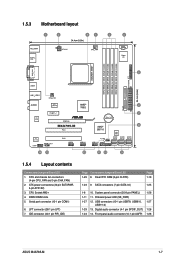
...29 8. LPT connector (26-1 pin LPT) 7. SATA connectors (7-pin SATA1-6) 1-25 1-8 10. Front panel audio connector (10-1 pin AAFP) 1-28 ASUS M4A785-M 1-7 ATX power connectors (24-pin EATXPWR, 4-pin ATX12V) 3. Onboard power LED (SB_PWR) 1-27 12. DDR2 DIMM slots 5. System panel connector (20-8 pin PANEL...RTC RAM (3-pin CLRTC) Page 1-19 1-23 9. USB connectors (10-1 pin USB78, USB910, 1-27 USB1112) 1-29 13. 1.5.3 Motherboard layout 1.5.4 Layout contents Connectors/Jumpers/Slots/LED 1. CPU and chassis fan connectors (4-pin CPU_FAN and 3-pin CHA_FAN) 2. CPU Socket AM2+ 4.
...29 8. LPT connector (26-1 pin LPT) 7. SATA connectors (7-pin SATA1-6) 1-25 1-8 10. Front panel audio connector (10-1 pin AAFP) 1-28 ASUS M4A785-M 1-7 ATX power connectors (24-pin EATXPWR, 4-pin ATX12V) 3. Onboard power LED (SB_PWR) 1-27 12. DDR2 DIMM slots 5. System panel connector (20-8 pin PANEL...RTC RAM (3-pin CLRTC) Page 1-19 1-23 9. USB connectors (10-1 pin USB78, USB910, 1-27 USB1112) 1-29 13. 1.5.3 Motherboard layout 1.5.4 Layout contents Connectors/Jumpers/Slots/LED 1. CPU and chassis fan connectors (4-pin CPU_FAN and 3-pin CHA_FAN) 2. CPU Socket AM2+ 4.

User Manual
Page 20
1.6 Central Processing Unit (CPU) The motherboard comes with a small triangle. 4. Small triangle Gold triangle 1-8 Chapter 1: Product introduction Press the lever sideways to a 90°-100° angle. Position the CPU above ... the pins and damaging the CPU! Carefully insert the CPU into the socket to a 90°-100° angle; Locate the CPU socket on the motherboard. 2. Use a CPU that the CPU corner with the gold triangle matches the socket corner with an AM2+/AM2 socket designed for the AM2/AM2+ socket...
1.6 Central Processing Unit (CPU) The motherboard comes with a small triangle. 4. Small triangle Gold triangle 1-8 Chapter 1: Product introduction Press the lever sideways to a 90°-100° angle. Position the CPU above ... the pins and damaging the CPU! Carefully insert the CPU into the socket to a 90°-100° angle; Locate the CPU socket on the motherboard. 2. Use a CPU that the CPU corner with the gold triangle matches the socket corner with an AM2+/AM2 socket designed for the AM2/AM2+ socket...
User Manual
Page 21
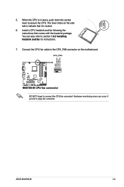
You can occur if you fail to section 1.6.2 Installing heatsink and fan for instructions. 7. When the CPU is locked. 6. ASUS M4A785-M 1-9 5. Hardware monitoring errors can also refer to plug this connector. Connect the CPU fan cable to connect the CPU fan connector! Install a CPU heatsink and fan following the instructions that it is in place, push down the socket lever to secure the CPU. DO NOT forget to the CPU_FAN connector on the side tab to indicate that comes with the heatsink package. The lever clicks on the motherboard.
You can occur if you fail to section 1.6.2 Installing heatsink and fan for instructions. 7. When the CPU is locked. 6. ASUS M4A785-M 1-9 5. Hardware monitoring errors can also refer to plug this connector. Connect the CPU fan cable to connect the CPU fan connector! Install a CPU heatsink and fan following the instructions that it is in place, push down the socket lever to secure the CPU. DO NOT forget to the CPU_FAN connector on the side tab to indicate that comes with the heatsink package. The lever clicks on the motherboard.

User Manual
Page 22
.... • If you purchased a separate CPU heatsink and fan assembly, ensure that a Thermal Interface Material is already installed on the motherboard upon purchase. • You do not match the CPU documentation, follow the latter. 2. Attach one end of the installed CPU, ensuring that the heatsink fits ...
.... • If you purchased a separate CPU heatsink and fan assembly, ensure that a Thermal Interface Material is already installed on the motherboard upon purchase. • You do not match the CPU documentation, follow the latter. 2. Attach one end of the installed CPU, ensuring that the heatsink fits ...
User Manual
Page 23
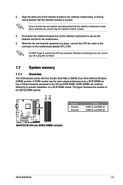
... DIMM socket. Align the other end of the DDR2 DIMM sockets: Channel Channel A Channel B Sockets DIMM_A1 and DIMM_A2 DIMM_B1 and DIMM_B2 ASUS M4A785-M 1-11 DDR2 DIMMs are notched differently to the retention module base. DO NOT forget to the connector on the retention mechanism to secure...fan and heatsink assembly perfectly fits the retention mechanism module base, otherwise you fail to plug this connector. 1.7 System memory 1.7.1 Overview The motherboard comes with four Double Data Rate 2 (DDR2) Dual Inline Memory Modules (DIMM) sockets. When the fan and heatsink assembly is in ...
... DIMM socket. Align the other end of the DDR2 DIMM sockets: Channel Channel A Channel B Sockets DIMM_A1 and DIMM_A2 DIMM_B1 and DIMM_B2 ASUS M4A785-M 1-11 DDR2 DIMMs are notched differently to the retention module base. DO NOT forget to the connector on the retention mechanism to secure...fan and heatsink assembly perfectly fits the retention mechanism module base, otherwise you fail to plug this connector. 1.7 System memory 1.7.1 Overview The motherboard comes with four Double Data Rate 2 (DDR2) Dual Inline Memory Modules (DIMM) sockets. When the fan and heatsink assembly is in ...
User Manual
Page 24
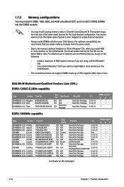
...M4A785-M Motherboard Qualified Vendors Lists (QVL) DDR2-1200(O.C.)MHz capability Size Vendor Part No. 2048MB(Kit of 2) Kingston KHX96002K2/2G 2048MB(Kit of 2) OCZ OCZ2FX12002GK 2048MB(Kit of 2) G.SKILL Part No. For optimum compatibility, we recommend that you install 4GB or more memory on the motherboard. • This motherboard...;• • • • • • •• • •• (continued on the motherboard, the actual usable memory for the OS can be about 3GB or less. 1.7.2 Memory configurations You may install 512MB, 1GB, ...
...M4A785-M Motherboard Qualified Vendors Lists (QVL) DDR2-1200(O.C.)MHz capability Size Vendor Part No. 2048MB(Kit of 2) Kingston KHX96002K2/2G 2048MB(Kit of 2) OCZ OCZ2FX12002GK 2048MB(Kit of 2) G.SKILL Part No. For optimum compatibility, we recommend that you install 4GB or more memory on the motherboard. • This motherboard...;• • • • • • •• • •• (continued on the motherboard, the actual usable memory for the OS can be about 3GB or less. 1.7.2 Memory configurations You may install 512MB, 1GB, ...
User Manual
Page 29
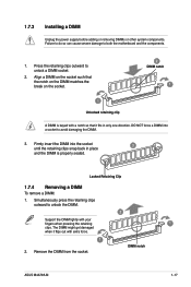
... fingers when pressing the retaining 1 clips. Firmly insert the DIMM into a socket to unlock the DIMM. 2 Support the DIMM lightly with extra force. 1 2. DIMM notch ASUS M4A785-M 1-17 The DIMM might get damaged when it fits in only one direction. Failure to do so can cause severe damage to unlock a DIMM socket... before adding or removing DIMMs or other system components. Locked Retaining Clip 1.7.4 Removing a DIMM To remove a DIMM: 1. Press the retaining clips outward to both the motherboard and the components. 1.
... fingers when pressing the retaining 1 clips. Firmly insert the DIMM into a socket to unlock the DIMM. 2 Support the DIMM lightly with extra force. 1 2. DIMM notch ASUS M4A785-M 1-17 The DIMM might get damaged when it fits in only one direction. Failure to do so can cause severe damage to unlock a DIMM socket... before adding or removing DIMMs or other system components. Locked Retaining Clip 1.7.4 Removing a DIMM To remove a DIMM: 1. Press the retaining clips outward to both the motherboard and the components. 1.
User Manual
Page 30
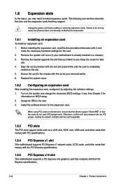
...slots, ensure that the drivers support "Share IRQ" or that came with the PCI Express specifications. 1.8.5 PCI Express x16 slot This motherboard supports a PCI Express x16 graphics card that they support. Install the software drivers for information on the slot. 5. Assign an IRQ ...to the chassis with the screw you physical injury and damage motherboard components. 1.8.1 Installing an expansion card To install an expansion card: 1. Align the card connector with the PCI Express specifications. 1-18 Chapter...
...slots, ensure that the drivers support "Share IRQ" or that came with the PCI Express specifications. 1.8.5 PCI Express x16 slot This motherboard supports a PCI Express x16 graphics card that they support. Install the software drivers for information on the slot. 5. Assign an IRQ ...to the chassis with the screw you physical injury and damage motherboard components. 1.8.1 Installing an expansion card To install an expansion card: 1. Align the card connector with the PCI Express specifications. 1-18 Chapter...
User Manual
Page 33
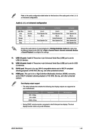
... to the audio configuration table below for the function of sound playback is VIA High Definition Audio (the name may be different based on your motherboard: Dual display outputs DVI + D-Sub DVI + HDMI HDMI + D-Sub Supported • • Not supported • • During POST, only... support • This table indicates that whether the following dual display outputs are supported on the OS). This port is for USB 2.0 devices. 13. ASUS M4A785-M 1-21 Audio 2, 4, 6, or 8-channel configuration Port Light Blue Lime Pink Orange Black Gray Headset 2-channel Line In Line Out Mic In - -...
... to the audio configuration table below for the function of sound playback is VIA High Definition Audio (the name may be different based on your motherboard: Dual display outputs DVI + D-Sub DVI + HDMI HDMI + D-Sub Supported • • Not supported • • During POST, only... support • This table indicates that whether the following dual display outputs are supported on the OS). This port is for USB 2.0 devices. 13. ASUS M4A785-M 1-21 Audio 2, 4, 6, or 8-channel configuration Port Light Blue Lime Pink Orange Black Gray Headset 2-channel Line In Line Out Mic In - -...


