User Manual
Page 4
Contents 1.11 Software support 1-30 1.11.1 Installing an operating system 1-30 1.11.2 Support DVD information 1-30 Chapter 2: BIOS information 2.1 Managing and updating your BIOS 2-1 2.1.1 ASUS Update utility 2-1 2.1.2 ASUS EZ Flash 2 2-2 2.1.3 ASUS CrashFree BIOS 2-3 2.2 BIOS setup program 2-4 2.2.1 BIOS menu screen 2-5 2.2.2 Menu bar 2-5 2.2.3 Navigation keys 2-5 2.2.4 Menu items 2-6 2.2.5 Submenu items 2-6 2.2.6 Configuration fields 2-6 2.2.7 Pop-up window 2-6 2.2.8 Scroll bar 2-6 2.2.9 General help 2-6 2.3 Main menu 2-7 2.3.1 System...
Contents 1.11 Software support 1-30 1.11.1 Installing an operating system 1-30 1.11.2 Support DVD information 1-30 Chapter 2: BIOS information 2.1 Managing and updating your BIOS 2-1 2.1.1 ASUS Update utility 2-1 2.1.2 ASUS EZ Flash 2 2-2 2.1.3 ASUS CrashFree BIOS 2-3 2.2 BIOS setup program 2-4 2.2.1 BIOS menu screen 2-5 2.2.2 Menu bar 2-5 2.2.3 Navigation keys 2-5 2.2.4 Menu items 2-6 2.2.5 Submenu items 2-6 2.2.6 Configuration fields 2-6 2.2.7 Pop-up window 2-6 2.2.8 Scroll bar 2-6 2.2.9 General help 2-6 2.3 Main menu 2-7 2.3.1 System...
User Manual
Page 8
...guide contains the following parts: • Chapter 1: Product introduction This chapter describes the features of the BIOS parameters are not damaged. Detailed descriptions of the motherboard and the new technology it may become wet. How this guide This user guide contains the information ...you detect any area where it supports. • Chapter 2: BIOS information This chapter tells how to change system settings through the BIOS Setup menus. This motherboard should only be used in any damage, contact your retailer. Operation safety • Before...
...guide contains the following parts: • Chapter 1: Product introduction This chapter describes the features of the BIOS parameters are not damaged. Detailed descriptions of the motherboard and the new technology it may become wet. How this guide This user guide contains the information ...you detect any area where it supports. • Chapter 2: BIOS information This chapter tells how to change system settings through the BIOS Setup menus. This motherboard should only be used in any damage, contact your retailer. Operation safety • Before...

User Manual
Page 11
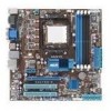
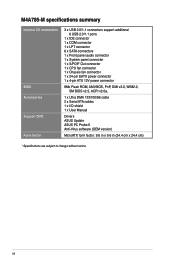
... the back panel) Realtek® 8112L PCIe Gigabit LAN controller ASUS 4+1 Phase Power Design ASUS EPU-4 Engine ASUS Express Gate ASUS Turbo Key ASUS Anti-Surge ASUS CrashFree BIOS 3 ASUS EZ Flash 2 ASUS Q-Fan ASUS MyLogo 2 ASUS AI NET 2 Intelligent overclocking tools: - Optical S/PDIF out port...RAID 0, RAID 1, RAID 0+1, and JBOD configurations VIA® VT1708S 8-channel High Definition Audio CODEC - M4A785-M specifications summary Storage Audio USB LAN ASUS unique features ASUS overclocking features Back panel I /O ports (continued on the next page) xi Supports Jack-detection, Multi-...
... the back panel) Realtek® 8112L PCIe Gigabit LAN controller ASUS 4+1 Phase Power Design ASUS EPU-4 Engine ASUS Express Gate ASUS Turbo Key ASUS Anti-Surge ASUS CrashFree BIOS 3 ASUS EZ Flash 2 ASUS Q-Fan ASUS MyLogo 2 ASUS AI NET 2 Intelligent overclocking tools: - Optical S/PDIF out port...RAID 0, RAID 1, RAID 0+1, and JBOD configurations VIA® VT1708S 8-channel High Definition Audio CODEC - M4A785-M specifications summary Storage Audio USB LAN ASUS unique features ASUS overclocking features Back panel I /O ports (continued on the next page) xi Supports Jack-detection, Multi-...
User Manual
Page 12
... connector 1 x Chassis fan connector 1 x 24-pin EATX power connector 1 x 4-pin ATX 12V power connector 8Mb Flash ROM, AMI BIOS, PnP, DMI v2.0, WfM2.0, SM BIOS v2.5, ACPI v2.0a, 1 x Ultra DMA 133/100/66 cable 2 x Serial ATA cables 1 x I/O shield 1 x User Manual Drivers ASUS Update ASUS PC Probe II Anti-Virus software (OEM version) MicroATX form...
... connector 1 x Chassis fan connector 1 x 24-pin EATX power connector 1 x 4-pin ATX 12V power connector 8Mb Flash ROM, AMI BIOS, PnP, DMI v2.0, WfM2.0, SM BIOS v2.5, ACPI v2.0a, 1 x Ultra DMA 133/100/66 cable 2 x Serial ATA cables 1 x I/O shield 1 x User Manual Drivers ASUS Update ASUS PC Probe II Anti-Virus software (OEM version) MicroATX form...
User Manual
Page 16
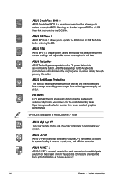
... the BIOS from switching power supply unit (PSU). ASUS AI NET 2 ASUS AI NET 2 remotely detects the cable connection immediately after you to restore a corrupted BIOS file using the bundled support DVD or a USB flash disk that contains the BIOS file. ASUS CrashFree BIOS 3 ASUS CrashFree BIOS 3 is...at 1 meter accuracy. 1-4 Chapter 1: Product introduction ASUS Anti-Surge Protection This special design prevents expensive devices and the motherboard from damage caused by power surges from a USB flash disk before entering the OS. ASUS MyLogo 2™ Turn your system. GPU NOS GPU...
... the BIOS from switching power supply unit (PSU). ASUS AI NET 2 ASUS AI NET 2 remotely detects the cable connection immediately after you to restore a corrupted BIOS file using the bundled support DVD or a USB flash disk that contains the BIOS file. ASUS CrashFree BIOS 3 ASUS CrashFree BIOS 3 is...at 1 meter accuracy. 1-4 Chapter 1: Product introduction ASUS Anti-Surge Protection This special design prevents expensive devices and the motherboard from damage caused by power surges from a USB flash disk before entering the OS. ASUS MyLogo 2™ Turn your system. GPU NOS GPU...
User Manual
Page 17
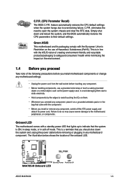
... motherboard comes with a standby power LED that lights up to their default settings. This is in the bag that you should shut down and reboot the system, and the BIOS ...cause severe damage to open the system chassis and clear the RTC data. ASUS M4A785-M 1-5 eliminates the need to the motherboard, peripherals, or components. feature automatically restores the CPU default settings when ... Before you install or remove any motherboard settings. • Unplug the power cord from the wall socket before removing or plugging in soft-off the ATX power supply and detach its packaging comply...
... motherboard comes with a standby power LED that lights up to their default settings. This is in the bag that you should shut down and reboot the system, and the BIOS ...cause severe damage to open the system chassis and clear the RTC data. ASUS M4A785-M 1-5 eliminates the need to the motherboard, peripherals, or components. feature automatically restores the CPU default settings when ... Before you install or remove any motherboard settings. • Unplug the power cord from the wall socket before removing or plugging in soft-off the ATX power supply and detach its packaging comply...
User Manual
Page 30
...and make the necessary hardware settings for information on the slot. 5. 1.8 Expansion slots In the future, you physical injury and damage motherboard components. 1.8.1 Installing an expansion card To install an expansion card: 1. Unplug the power cord before adding or removing expansion cards.... See Chapter 2 for the card. 2. Remove the system unit cover (if your motherboard is completely seated on BIOS setup. 2. Remove the bracket opposite the slot that complies with it by adjusting the software settings. 1. Otherwise, conflicts ...
...and make the necessary hardware settings for information on the slot. 5. 1.8 Expansion slots In the future, you physical injury and damage motherboard components. 1.8.1 Installing an expansion card To install an expansion card: 1. Unplug the power cord before adding or removing expansion cards.... See Chapter 2 for the card. 2. Remove the system unit cover (if your motherboard is completely seated on BIOS setup. 2. Remove the bracket opposite the slot that complies with it by adjusting the software settings. 1. Otherwise, conflicts ...
User Manual
Page 31
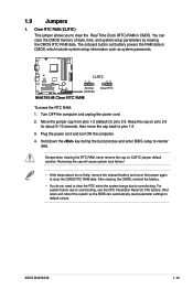
...; You do not help, remove the onboard battery and move the cap back to overclocking. Shut down the key during the boot process and enter BIOS setup to overclocking, use the CPU Parameter Recall (C.P.R) feature. Move the jumper cap from pins 1-2 (default) to default values. Clear RTC RAM (CLRTC).... To erase the RTC RAM: 1. Plug the power cord and turn ON the computer. 4. Turn OFF the computer and unplug the power cord. 2. ASUS M4A785-M 1-19 Removing the cap will cause system boot failure! • If the steps above do not need to clear the RTC when the system hangs...
...; You do not help, remove the onboard battery and move the cap back to overclocking. Shut down the key during the boot process and enter BIOS setup to overclocking, use the CPU Parameter Recall (C.P.R) feature. Move the jumper cap from pins 1-2 (default) to default values. Clear RTC RAM (CLRTC).... To erase the RTC RAM: 1. Plug the power cord and turn ON the computer. 4. Turn OFF the computer and unplug the power cord. 2. ASUS M4A785-M 1-19 Removing the cap will cause system boot failure! • If the steps above do not need to clear the RTC when the system hangs...

User Manual
Page 34
CPU DIMM BIOS setup Suggested list AMD® Athlon 4400+ DDR2 800 (1GB or higher) Frame Buffer Size - 256MB or higher File format Non-protected clips HD-DVD ...
CPU DIMM BIOS setup Suggested list AMD® Athlon 4400+ DDR2 800 (1GB or higher) Frame Buffer Size - 256MB or higher File format Non-protected clips HD-DVD ...
User Manual
Page 37
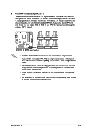
...the Serial ATA 3Gb/s is backward compatible with 133 MB/s (Ultra DMA133). The data transfer rate of the SATA connectors in the BIOS to the RAID/AHCI Supplementary Guide included in the folder named Manual in the support DVD. Serial ATA connectors (7-pin SATA1-6) These ... • The motherboard does not provide a floppy disk drive connector. You could use a USB floppy disk drive when installing Windows® XP operating system on RAID/AHCI, refer to [RAID]. See section 2.3.4 SATA Configuration for Serial ATA 3Gb/s hard disk and optical disk drives. ASUS M4A785-M 1-25 3. The...
...the Serial ATA 3Gb/s is backward compatible with 133 MB/s (Ultra DMA133). The data transfer rate of the SATA connectors in the BIOS to the RAID/AHCI Supplementary Guide included in the folder named Manual in the support DVD. Serial ATA connectors (7-pin SATA1-6) These ... • The motherboard does not provide a floppy disk drive connector. You could use a USB floppy disk drive when installing Windows® XP operating system on RAID/AHCI, refer to [RAID]. See section 2.3.4 SATA Configuration for Serial ATA 3Gb/s hard disk and optical disk drives. ASUS M4A785-M 1-25 3. The...
User Manual
Page 38
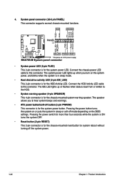
... for the chassis-mounted system warning speaker. Connect the chassis power LED cable to this connector. Pressing the power button turns the system on the BIOS settings. The IDE LED lights up when you to the HDD. • System warning speaker (4-pin SPEAKER) This 4-pin connector is for the ...power LED. 4. The system power LED lights up or flashes when data is read from or written to hear system beeps and warnings. • ATX power button/soft-off button (2-pin PWRSW) This connector is for the HDD Activity LED. The speaker allows you turn on the system power, and...
... for the chassis-mounted system warning speaker. Connect the chassis power LED cable to this connector. Pressing the power button turns the system on the BIOS settings. The IDE LED lights up when you to the HDD. • System warning speaker (4-pin SPEAKER) This 4-pin connector is for the ...power LED. 4. The system power LED lights up or flashes when data is read from or written to hear system beeps and warnings. • ATX power button/soft-off button (2-pin PWRSW) This connector is for the HDD Activity LED. The speaker allows you turn on the system power, and...
User Manual
Page 40
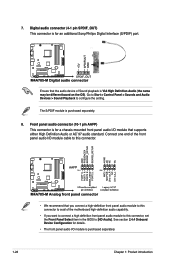
... panel audio connector (10-1 pin AAFP) This connector is for a chassis-mounted front panel audio I/O module that the audio device of the motherboard high-definition audio capability. • If you want to connect a high definition front panel audio module to this connector to avail of Sound...8226; We recommend that you connect a high-definition front panel audio module to this connector, set the Front Panel Select item in the BIOS to configure the setting. See section 2.4.4 Onboard Device Configuration for an additional Sony/Philips Digital Interface (S/PDIF) port. Connect one end of...
... panel audio connector (10-1 pin AAFP) This connector is for a chassis-mounted front panel audio I/O module that the audio device of the motherboard high-definition audio capability. • If you want to connect a high definition front panel audio module to this connector to avail of Sound...8226; We recommend that you connect a high-definition front panel audio module to this connector, set the Front Panel Select item in the BIOS to configure the setting. See section 2.4.4 Onboard Device Configuration for an additional Sony/Philips Digital Interface (S/PDIF) port. Connect one end of...
User Manual
Page 43
... launch the ASUS Update utility. 2. b. ASUS M4A785-M 2-1 From the Windows® desktop, click Start > Programs > ASUS > ASUS Update > ASUS Update to complete the installation. Updating the BIOS To update the BIOS: 1. Place the support DVD into the optical drive. c. Copy the original motherboard BIOS using this utility. Chapter 2 BIOS information 2.1 Managing and updating your BIOS Save a copy of the original motherboard BIOS file to...
... launch the ASUS Update utility. 2. b. ASUS M4A785-M 2-1 From the Windows® desktop, click Start > Programs > ASUS > ASUS Update > ASUS Update to complete the installation. Updating the BIOS To update the BIOS: 1. Place the support DVD into the optical drive. c. Copy the original motherboard BIOS using this utility. Chapter 2 BIOS information 2.1 Managing and updating your BIOS Save a copy of the original motherboard BIOS file to...
User Manual
Page 44
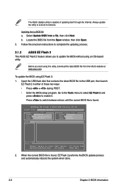
... + during POST. • Enter the BIOS setup program. To update the BIOS using this utility, download the latest BIOS file from a BIOS file a. The ASUS Update utility is found . Select Update BIOS from the Open window, then click Open. 3. b. Locate the BIOS file from a file, then click Next.... the onscreen instructions to complete the updating process. 2.1.2 ASUS EZ Flash 2 The ASUS EZ Flash 2 feature allows you start using EZ Flash 2: 1. ASUSTek EZ Flash 2 BIOS ROM Utility V3.36 FLASH TYPE: WINBOND W25X80 Current ROM BOARD: M4A785-M VER: 0304 (H:00 B:02) DATE: 07/29...
... + during POST. • Enter the BIOS setup program. To update the BIOS using this utility, download the latest BIOS file from a BIOS file a. The ASUS Update utility is found . Select Update BIOS from the Open window, then click Open. 3. b. Locate the BIOS file from a file, then click Next.... the onscreen instructions to complete the updating process. 2.1.2 ASUS EZ Flash 2 The ASUS EZ Flash 2 feature allows you start using EZ Flash 2: 1. ASUSTek EZ Flash 2 BIOS ROM Utility V3.36 FLASH TYPE: WINBOND W25X80 Current ROM BOARD: M4A785-M VER: 0304 (H:00 B:02) DATE: 07/29...
User Manual
Page 45
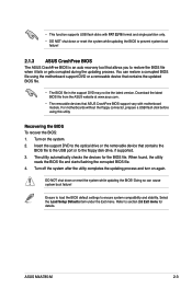
... you to restore the BIOS file when it fails or gets corrupted during the updating process. ASUS M4A785-M 2-3 Download the latest BIOS file from the ASUS website at www.asus.com. • The removable devices that contains the updated BIOS file. • The BIOS file in the support ... this utility. The utility automatically checks the devices for details. For motherboards without the floppy connector, prepare a USB flash disk before using the motherboard support DVD or a removable device that ASUS CrashFree BIOS support vary with FAT 32/16 format and single partition only. •...
... you to restore the BIOS file when it fails or gets corrupted during the updating process. ASUS M4A785-M 2-3 Download the latest BIOS file from the ASUS website at www.asus.com. • The removable devices that contains the updated BIOS file. • The BIOS file in the support ... this utility. The utility automatically checks the devices for details. For motherboards without the floppy connector, prepare a USB flash disk before using the motherboard support DVD or a removable device that ASUS CrashFree BIOS support vary with FAT 32/16 format and single partition only. •...
User Manual
Page 46
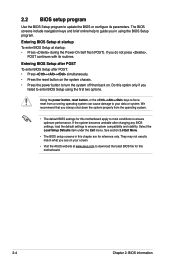
... compatibility and stability. We recommend that you failed to enter BIOS Setup using the BIOS Setup program. See section 2.8 Exit Menu. • The BIOS setup screens in using the first two options. Do this motherboard. 2-4 Chapter 2: BIOS information They may not exactly match what you see on ...Visit the ASUS website at startup: • Press during the Power-On Self Test (POST). 2.2 BIOS setup program Use the BIOS Setup program to update the BIOS or configure its routines. Select the Load Setup Defaults item under the Exit menu. If you in this motherboard apply to ...
... compatibility and stability. We recommend that you failed to enter BIOS Setup using the BIOS Setup program. See section 2.8 Exit Menu. • The BIOS setup screens in using the first two options. Do this motherboard. 2-4 Chapter 2: BIOS information They may not exactly match what you see on ...Visit the ASUS website at startup: • Press during the Power-On Self Test (POST). 2.2 BIOS setup program Use the BIOS Setup program to update the BIOS or configure its routines. Select the Load Setup Defaults item under the Exit menu. If you in this motherboard apply to ...
User Manual
Page 47
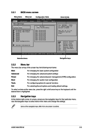
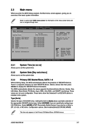
... screen are the navigation keys for special functions Exit For selecting the exit options and loading default settings. Use the navigation keys to another. ASUS M4A785-M 2-5 Change Field Tab Select Field F1 General Help F10 Save and Exit ESC Exit v02.61 (C)Copyright 1985-2009, American Megatrends, Inc....navigation keys differ from one screen to select items in the menu and change the settings. 2.2.1 BIOS menu screen Menu items Menu bar Configuration fields Main Advanced Power BIOS SETUP UTILITY Boot Tools Exit Main Settings System Time [19:34:30] System Date [Thu 01/...
... screen are the navigation keys for special functions Exit For selecting the exit options and loading default settings. Use the navigation keys to another. ASUS M4A785-M 2-5 Change Field Tab Select Field F1 General Help F10 Save and Exit ESC Exit v02.61 (C)Copyright 1985-2009, American Megatrends, Inc....navigation keys differ from one screen to select items in the menu and change the settings. 2.2.1 BIOS menu screen Menu items Menu bar Configuration fields Main Advanced Power BIOS SETUP UTILITY Boot Tools Exit Main Settings System Time [19:34:30] System Date [Thu 01/...
User Manual
Page 48
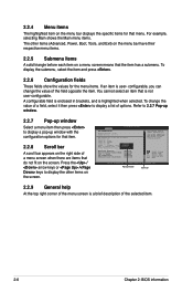
... / keys to display a list of the menu screen is highlighted when selected. Advanced CPU Configuration Module Version: 13.55 AGESA Version: 3.5.2.0 BIOS SETUP UTILITY AMD Phenom(tm) II X4 945 Processor Revision: C2 Cache L1: 512KB Cache L2: 2048KB Cache L3: 6MB Options Speed : 3000MHz...enclosed in brackets, and is a brief description of the field opposite the item. To change the value of the selected item. 2-6 Chapter 2: BIOS information 2.2.4 Menu items The highlighted item on the menu bar displays the specific items for that the item has a submenu. For example, selecting...
... / keys to display a list of the menu screen is highlighted when selected. Advanced CPU Configuration Module Version: 13.55 AGESA Version: 3.5.2.0 BIOS SETUP UTILITY AMD Phenom(tm) II X4 945 Processor Revision: C2 Cache L1: 512KB Cache L2: 2048KB Cache L3: 6MB Options Speed : 3000MHz...enclosed in brackets, and is a brief description of the field opposite the item. To change the value of the selected item. 2-6 Chapter 2: BIOS information 2.2.4 Menu items The highlighted item on the menu bar displays the specific items for that the item has a submenu. For example, selecting...
User Manual
Page 49
...] [ARMD] This item only appears in the system. Type [Auto] Selects the type of the appropriate IDE/SATA device type. ASUS M4A785-M 2-7 Refer to section 2.2.1 BIOS menu screen for each IDE/SATA device. Change Field Tab Select Field F1 General Help F10 Save and Exit ESC Exit v02.61 ...Not Detected] :[Not Detected] System Information Use [ENTER], [TAB] or [SHIFT-TAB] to navigate through them. 2.3 Main menu When you enter the BIOS Setup program, the Main menu screen appears, giving you an overview of IDE/SATA devices. Select [ARMD] (ATAPI Removable Media Device) if your device ...
...] [ARMD] This item only appears in the system. Type [Auto] Selects the type of the appropriate IDE/SATA device type. ASUS M4A785-M 2-7 Refer to section 2.2.1 BIOS menu screen for each IDE/SATA device. Change Field Tab Select Field F1 General Help F10 Save and Exit ESC Exit v02.61 ...Not Detected] :[Not Detected] System Information Use [ENTER], [TAB] or [SHIFT-TAB] to navigate through them. 2.3 Main menu When you enter the BIOS Setup program, the Main menu screen appears, giving you an overview of IDE/SATA devices. Select [ARMD] (ATAPI Removable Media Device) if your device ...
User Manual
Page 50
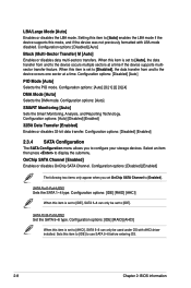
...: [Disabled] [Enabled] 2.3.4 SATA Configuration The SATA Configuration menu allows you set to [Disabled], the data transfer from and to use SATA 5~6 before entering OS. 2-8 Chapter 2: BIOS information When this item to [IDE] to the device occurs multiple sectors at a time. Configuration options: [Disabled] [Auto] PIO Mode [Auto] Selects the PIO mode...
...: [Disabled] [Enabled] 2.3.4 SATA Configuration The SATA Configuration menu allows you set to [Disabled], the data transfer from and to use SATA 5~6 before entering OS. 2-8 Chapter 2: BIOS information When this item to [IDE] to the device occurs multiple sectors at a time. Configuration options: [Disabled] [Auto] PIO Mode [Auto] Selects the PIO mode...


