Service Guide
Page 7
...Acer eRecovery Management 26 Acer eSettings Management 28 Using the System Utilities 30 Hardware Specification and Configurations 33 System Utilities 39 BIOS Setup Utility 39 Invoking BIOS Setup 40 Information 41 Main 42 Advanced 44 Security 45 Boot 49 Exit 50 BIOS Flash Utility 51 HDD unlock Utility 52 Machine Disassembly... and Replacement 53 General Information 54 Before You Begin 54 Disassembly Procedure Flowchard 55 Removing the Battery Pack 57 Removing HDD/Wirless Cover/RAM Module...
...Acer eRecovery Management 26 Acer eSettings Management 28 Using the System Utilities 30 Hardware Specification and Configurations 33 System Utilities 39 BIOS Setup Utility 39 Invoking BIOS Setup 40 Information 41 Main 42 Advanced 44 Security 45 Boot 49 Exit 50 BIOS Flash Utility 51 HDD unlock Utility 52 Machine Disassembly... and Replacement 53 General Information 54 Before You Begin 54 Disassembly Procedure Flowchard 55 Removing the Battery Pack 57 Removing HDD/Wirless Cover/RAM Module...

Service Guide
Page 63
...-step procedures on how to avoid mismatch when putting back the components. During the disassembly process, group the screws with the corresponding components to disassemble the notebook computer Aspire 6935G for the different components vary in size. Chapter 3 53 To disassemble the computer, you remove the stripe cover, please be careful not to scrape the...
...-step procedures on how to avoid mismatch when putting back the components. During the disassembly process, group the screws with the corresponding components to disassemble the notebook computer Aspire 6935G for the different components vary in size. Chapter 3 53 To disassemble the computer, you remove the stripe cover, please be careful not to scrape the...
Service Guide
Page 64
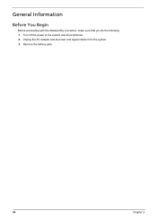
Unplug the AC adapter and all peripherals. 2. Turn off the power to the system and all power and signal cables from the system. 3. Remove the battery pack. 54 Chapter 3 General Information Before You Begin Before proceeding with the disassembly procedure, make sure that you do the following: 1.
Unplug the AC adapter and all peripherals. 2. Turn off the power to the system and all power and signal cables from the system. 3. Remove the battery pack. 54 Chapter 3 General Information Before You Begin Before proceeding with the disassembly procedure, make sure that you do the following: 1.
Service Guide
Page 65
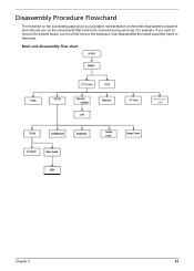
Main unit disassembly flow chart Chapter 3 55 For example, if you want to remove the system board, you on the entire disassembly sequence and instructs you must first remove the keyboard, then disassemble the inside assembly frame in that need to be removed during servicing. Disassembly Procedure Flowchard The flowchart on the succeeding page gives you a graphic representation on the components that order.
Main unit disassembly flow chart Chapter 3 55 For example, if you want to remove the system board, you on the entire disassembly sequence and instructs you must first remove the keyboard, then disassemble the inside assembly frame in that need to be removed during servicing. Disassembly Procedure Flowchard The flowchart on the succeeding page gives you a graphic representation on the components that order.
Service Guide
Page 72
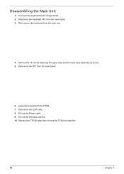
Turn over the keyboard as shown. 5. Remove the 18 screws fastening the upper case and the lower case assembly as the image shows. 2. Disconnect the LCM cable. 8. Pull out the Wireless antenna. 10. Release four TPCB locker then remove the TCB from the main unit. 4. Then remove the keyboard from machine. 62 Chapter 3 Loose two screws from the main board 3. Disconnect the Keyboard FFC from the TPCB. 7. Disconnect the FFC from the main board. 6. Pull out the Power cable. 9. Disassembling the Main Unit 1.
Turn over the keyboard as shown. 5. Remove the 18 screws fastening the upper case and the lower case assembly as the image shows. 2. Disconnect the LCM cable. 8. Pull out the Wireless antenna. 10. Release four TPCB locker then remove the TCB from the main unit. 4. Then remove the keyboard from machine. 62 Chapter 3 Loose two screws from the main board 3. Disconnect the Keyboard FFC from the TPCB. 7. Disconnect the FFC from the main board. 6. Pull out the Power cable. 9. Disassembling the Main Unit 1.
Service Guide
Page 73
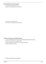
Loose the LED boards four screws. 12. Loose the daughter board screw then remove the daughter board from the machine. Loose four LCM hinge screws. 14. Then remove LCM module from the machine. 16. Disconnect LED/B cable and USB/B FFC. Remove two LED boards from the BTCB.. 19. Remove M/B from the machine. 13. Loose the M/B screw, remove RJ11 connector from the BTCB. 18. Disconnect four cables on the M/B as shown. 17. Chapter 3 63 Remove I/O baord and Main Board. 15. Disassembling the LED boards 11.
Loose the LED boards four screws. 12. Loose the daughter board screw then remove the daughter board from the machine. Loose four LCM hinge screws. 14. Then remove LCM module from the machine. 16. Disconnect LED/B cable and USB/B FFC. Remove two LED boards from the BTCB.. 19. Remove M/B from the machine. 13. Loose the M/B screw, remove RJ11 connector from the BTCB. 18. Disconnect four cables on the M/B as shown. 17. Chapter 3 63 Remove I/O baord and Main Board. 15. Disassembling the LED boards 11.

Service Guide
Page 74
Remove LCM bezel. 4. Disconnect CCD cable. 6. Remove Modem card from the hinge. 64 Chapter 3 Disassembly LCM module 1. 20. Disconnect Modem card cable. 23. Loose 11 LCM bezel screws. 3. Loose four LCD scrws from the M/B. Disconnect Inverter cable and Back LED board cable. 5. Loose two Modem card screws. 22. Remove the USB board from BTCB. 21. Remove six LCM bezel mylar. 2.
Remove LCM bezel. 4. Disconnect CCD cable. 6. Remove Modem card from the hinge. 64 Chapter 3 Disassembly LCM module 1. 20. Disconnect Modem card cable. 23. Loose 11 LCM bezel screws. 3. Loose four LCD scrws from the M/B. Disconnect Inverter cable and Back LED board cable. 5. Loose two Modem card screws. 22. Remove the USB board from BTCB. 21. Remove six LCM bezel mylar. 2.

Service Guide
Page 76
Disassembling the External Modules Disassembling the HDD Module 1. Remove the four screws holding the optical bracket. 2. two on each side. 2. Disassembling the ODD Module 1. Remove the two screws holding the HDD (hard disk drive) foil; Then remove the optical bracket from the HDD foil. Carefully take out the hard disk drive from the optical disk drive. 66 Chapter 3
Disassembling the External Modules Disassembling the HDD Module 1. Remove the four screws holding the optical bracket. 2. two on each side. 2. Disassembling the ODD Module 1. Remove the two screws holding the HDD (hard disk drive) foil; Then remove the optical bracket from the HDD foil. Carefully take out the hard disk drive from the optical disk drive. 66 Chapter 3


