Aspire 6935 Series Quick Guide
Page 5
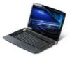
... mouse. Easy-launch button Buttons for video communication. Empowering key Launch Acer Empowering Technology 5 English # Icon 1 2 3 4 5 6 7 8 9 10 11 12 13 14 Item Acer Crystal Eye Acer PureZone Display screen Status indicators Power button Description Web camera for launching frequently...Click buttons (left, center* and right) The left and right mouse buttons. *The center button serves as Acer Bio-Protection fingerprint reader supporting Acer FingerNav 4-way control function (only for certain models). Speakers 2.1 speakers deliver stereo audio output. CineDash media The...
... mouse. Easy-launch button Buttons for video communication. Empowering key Launch Acer Empowering Technology 5 English # Icon 1 2 3 4 5 6 7 8 9 10 11 12 13 14 Item Acer Crystal Eye Acer PureZone Display screen Status indicators Power button Description Web camera for launching frequently...Click buttons (left, center* and right) The left and right mouse buttons. *The center button serves as Acer Bio-Protection fingerprint reader supporting Acer FingerNav 4-way control function (only for certain models). Speakers 2.1 speakers deliver stereo audio output. CineDash media The...
Service Guide
Page 7
... Technology 19 Empowering Technology password 20 Acer eAudio Management 21 Acer ePower Management 22 Acer eDataSecurity Management (for selected models 24 Acer eRecovery Management 26 Acer eSettings Management 28 Using the System Utilities 30 Hardware Specification and Configurations 33 System Utilities 39 BIOS Setup Utility 39 Invoking BIOS Setup 40 Information 41 Main 42 Advanced 44 Security...
... Technology 19 Empowering Technology password 20 Acer eAudio Management 21 Acer ePower Management 22 Acer eDataSecurity Management (for selected models 24 Acer eRecovery Management 26 Acer eSettings Management 28 Using the System Utilities 30 Hardware Specification and Configurations 33 System Utilities 39 BIOS Setup Utility 39 Invoking BIOS Setup 40 Information 41 Main 42 Advanced 44 Security...
Service Guide
Page 8
...) Error Message 73 Index of Error Messages 74 Phoenix BIOS Beep Codes 77 Index of Symptom-to-FRU Error Message 81 Intermittent Problems 85 Undetermined Problems 86 Jumper and Connector Locations 87 Top View 87 Bottom View 88 FRU (Field Replaceable Unit) List 91 Aspire 6935G Exploded Diagram 92 Aspire 6935G FRU List 108 VIII
...) Error Message 73 Index of Error Messages 74 Phoenix BIOS Beep Codes 77 Index of Symptom-to-FRU Error Message 81 Intermittent Problems 85 Undetermined Problems 86 Jumper and Connector Locations 87 Top View 87 Bottom View 88 FRU (Field Replaceable Unit) List 91 Aspire 6935G Exploded Diagram 92 Aspire 6935G FRU List 108 VIII

Service Guide
Page 25
To activate hotkeys, press and hold the key before pressing the other key in the hotkey combination. Hot Keys The computer employs hotkeys or key combinations to access most of the computer's controls like sreen brightness, volume output and the BIOS utility. Hotkey + + + + + + + + + > +
To activate hotkeys, press and hold the key before pressing the other key in the hotkey combination. Hot Keys The computer employs hotkeys or key combinations to access most of the computer's controls like sreen brightness, volume output and the BIOS utility. Hotkey + + + + + + + + + > +
Service Guide
Page 36
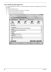
Acer eSettings Management Acer eSettings Management allows you set BIOS passwords and modify boot options. Acer eSettings Management also: ‰ Provides a simple graphical user interface for navigation. ‰ Prints and saves hardware specifications. ‰ Lets you to inspect hardware specifications, set an asset tag for your system. 28 Chapter 1
Acer eSettings Management Acer eSettings Management allows you set BIOS passwords and modify boot options. Acer eSettings Management also: ‰ Provides a simple graphical user interface for navigation. ‰ Prints and saves hardware specifications. ‰ Lets you to inspect hardware specifications, set an asset tag for your system. 28 Chapter 1
Service Guide
Page 45
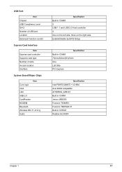
... Built-in ICH8M 2 USB 1.1 and USB 2.0 Host controller 4 One on the right side Enable/Disable by BIOS Setup Specification Built-in ICH8M 75mmx54mm(W)x5mm One Left Side PCI Express Specification Intel PM975/GM975 + ICH8M Acer MXM compatible ATHEROS_AR8121 Built in ICH8M Jmicro JMB385 Foxconn T60M951 Foxconn T60H928.01 Built-in ICH8-M Realtek...
... Built-in ICH8M 2 USB 1.1 and USB 2.0 Host controller 4 One on the right side Enable/Disable by BIOS Setup Specification Built-in ICH8M 75mmx54mm(W)x5mm One Left Side PCI Express Specification Intel PM975/GM975 + ICH8M Acer MXM compatible ATHEROS_AR8121 Built in ICH8M Jmicro JMB385 Foxconn T60M951 Foxconn T60H928.01 Built-in ICH8-M Realtek...
Service Guide
Page 49
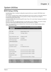
...m during POST to enter multi-boot menu. However, if you encounter configuration problems, you want to change boot device without entering BIOS Setup Utility, please set to "disabled". If you may need to run Setup. Chapter 2 39 Press during POST (when "Press... Your computer is a hardware configuration program built into your computer's BIOS (Basic Input/ Output System). Please also refer to enter setup. The default parameter of screen). Chapter 2 System Utilities BIOS Setup Utility The BIOS Setup Utility is already properly configured and optimized, and you do ...
...m during POST to enter multi-boot menu. However, if you encounter configuration problems, you want to change boot device without entering BIOS Setup Utility, please set to "disabled". If you may need to run Setup. Chapter 2 39 Press during POST (when "Press... Your computer is a hardware configuration program built into your computer's BIOS (Basic Input/ Output System). Please also refer to enter setup. The default parameter of screen). Chapter 2 System Utilities BIOS Setup Utility The BIOS Setup Utility is already properly configured and optimized, and you do ...
Service Guide
Page 50
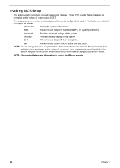
... to enter Setup message is enclosed in the Item Specific Help part of the screen. Navigation keys for parameters are found in square brackets. Invoking BIOS Setup The setup function can change the value of a parameter if it is prompted on the bottom of the screen. The features are shown on...
... to enter Setup message is enclosed in the Item Specific Help part of the screen. Navigation keys for parameters are found in square brackets. Invoking BIOS Setup The setup function can change the value of a parameter if it is prompted on the bottom of the screen. The features are shown on...
Service Guide
Page 51
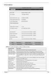
Displays system BIOS version. This field shows product name of devices installed on secondary IDE master. This will be visible only when an internal LAN device is subject ... version of HDD installed on primary IDE master. ParameterItem CPU Type IDE1 Model Name IDE1 Serial Number IDE2I Model Name IDE2 Serial Number System BIOS ver VGA BIOS Ver KBC Ver Serial Number Asset Tag Number Product Name Manufacturer Name UUID Number Description This field shows the CPU type and speed of...
Displays system BIOS version. This field shows product name of devices installed on secondary IDE master. This will be visible only when an internal LAN device is subject ... version of HDD installed on primary IDE master. ParameterItem CPU Type IDE1 Model Name IDE1 Serial Number IDE2I Model Name IDE2 Serial Number System BIOS ver VGA BIOS Ver KBC Ver Serial Number Asset Tag Number Product Name Manufacturer Name UUID Number Description This field shows the CPU type and speed of...
Service Guide
Page 54
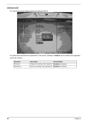
Parameter Serial port Parallel port Description Displays the settings of the serial port Shows the settings of the parallel port Format/Option Enabled or Disabled Enabled or Disabled 44 Chapter 2 Advanced The Advanced screen displays advanced settings in boldface are the default and suggested parameter settings. Settings in BIOS. The table below describes the parameters in this screen.
Parameter Serial port Parallel port Description Displays the settings of the serial port Shows the settings of the parallel port Format/Option Enabled or Disabled Enabled or Disabled 44 Chapter 2 Advanced The Advanced screen displays advanced settings in boldface are the default and suggested parameter settings. Settings in BIOS. The table below describes the parameters in this screen.
Service Guide
Page 56
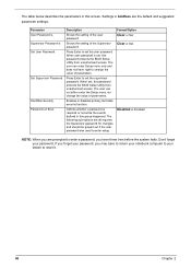
...Defines whether a password is set , this group happened. When user password is required or not while the events defined in this password protects the BIOS Setup Utility from unauthorized access. Format/Option Clear or Set Clear or Set Disabled or Enabled NOTE: When you are prompted to enter a password, ... the system halts. Enables or disables primary hard disk security function. The table below describes the parameters in this password protects the BIOS Setup Utility from unauthorized access. The user can not either enter the Setup menu nor change the value of parameters.
...Defines whether a password is set , this group happened. When user password is required or not while the events defined in this password protects the BIOS Setup Utility from unauthorized access. Format/Option Clear or Set Clear or Set Disabled or Enabled NOTE: When you are prompted to enter a password, ... the system halts. Enables or disables primary hard disk security function. The table below describes the parameters in this password protects the BIOS Setup Utility from unauthorized access. The user can not either enter the Setup menu nor change the value of parameters.
Service Guide
Page 57
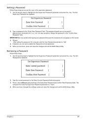
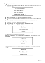
...do not appear on boot parameter. 5. Removing a Password Follow these steps as you are done, press u to save the changes and exit the BIOS Setup Utility. The Set Password box appears: 2. Press e twice without typing anything in the "Enter New Password" field. The password length can ...opt to save the changes and exit the BIOS Setup Utility. Retype the password in the Enter Current Password field and press e. 3. Type the current password in the "Confirm New Password" field....
...do not appear on boot parameter. 5. Removing a Password Follow these steps as you are done, press u to save the changes and exit the BIOS Setup Utility. The Set Password box appears: 2. Press e twice without typing anything in the "Enter New Password" field. The password length can ...opt to save the changes and exit the BIOS Setup Utility. Retype the password in the Enter Current Password field and press e. 3. Type the current password in the "Confirm New Password" field....
Service Guide
Page 58
... new password and confirm new password strings do not match, the screen will show you are done, press u to save the changes and exit the BIOS Setup Utility. Type the current password in the Confirm New Password field. 4. After setting the password, the computer sets the User Password parameter to highlight...
... new password and confirm new password strings do not match, the screen will show you are done, press u to save the changes and exit the BIOS Setup Utility. Type the current password in the Confirm New Password field. 4. After setting the password, the computer sets the User Password parameter to highlight...
Service Guide
Page 61
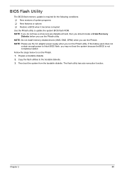
...Prepare a bootable diskette. 2. The flash utility has auto-execution function. Then boot the system from the bootable diskette. Fellow the steps below to finish BIOS flash, you use the Phlash. NOTE: If you do not have a crisis recovery diskette at hand, then you should create a Crisis Recovery Diskette before... you may not boot the system because the BIOS is required for the following conditions: ‰ New versions of system programs ‰ New features or options ‰ Restore...
...Prepare a bootable diskette. 2. The flash utility has auto-execution function. Then boot the system from the bootable diskette. Fellow the steps below to finish BIOS flash, you use the Phlash. NOTE: If you do not have a crisis recovery diskette at hand, then you should create a Crisis Recovery Diskette before... you may not boot the system because the BIOS is required for the following conditions: ‰ New versions of system programs ‰ New features or options ‰ Restore...
Service Guide
Page 81
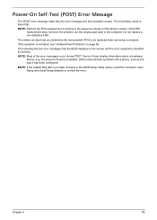
... cause is not listed, see "Undetermined Problems" on the screen and the error symptoms classified by function. The following lists the error messages that the BIOS displays on page 86. If the symptom is listed first. NOTE: Most of memory installed. NOTE: If the system fails after you determine the next... actions in the sequence shown in FRU/Action column, if the FRU replacement does not solve the problem, put the original part back in the BIOS Setup Utility menus, reset the computer, enter Setup and install Setup defaults or correct the error.
... cause is not listed, see "Undetermined Problems" on the screen and the error symptoms classified by function. The following lists the error messages that the BIOS displays on page 86. If the symptom is listed first. NOTE: Most of memory installed. NOTE: If the system fails after you determine the next... actions in the sequence shown in FRU/Action column, if the FRU replacement does not solve the problem, put the original part back in the BIOS Setup Utility menus, reset the computer, enter Setup and install Setup defaults or correct the error.
Service Guide
Page 82
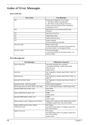
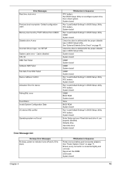
... 070 071 072 110 Error Message List Error Messages Failure Fixed Disk Stuck Key Keyboard error Keyboard Controller Failed Keyboard locked - CPU BIOS Update Code Mismatch. 2. Hard disk drive System board see "Keyboard or Auxiliary Input Device Check" on page 70. Unlock external ...Sequence Reconnect hard disk drive connector. Default configuration used System timer error 74 Error Messages Equipment Configuration Error causes: 1. FRU/Action in BIOS Setup Utility. System board Chapter 4 Run Setup Shadow RAM Failed at offset: nnnn System RAM Failed at offset: nnnn Extended RAM ...
... 070 071 072 110 Error Message List Error Messages Failure Fixed Disk Stuck Key Keyboard error Keyboard Controller Failed Keyboard locked - CPU BIOS Update Code Mismatch. 2. Hard disk drive System board see "Keyboard or Auxiliary Input Device Check" on page 70. Unlock external ...Sequence Reconnect hard disk drive connector. Default configuration used System timer error 74 Error Messages Equipment Configuration Error causes: 1. FRU/Action in BIOS Setup Utility. System board Chapter 4 Run Setup Shadow RAM Failed at offset: nnnn System RAM Failed at offset: nnnn Extended RAM ...
Service Guide
Page 83
... Utility. Ensure every connector is blank. DIMM System board Check the drive is defined with the proper diskette type in BIOS Setup Utility. Error Messages Real time clock error Previous boot incomplete - See "External Diskette Drive Check" on page 71. Diskette ...-on indicator turns off and LCD is connected tightly and correctly. System board Run "Load Default Settings" in BIOS Setup Utility. RTC battery System board Run "Load Default Settings" in BIOS Setup Utility. Default configuration used. Check the drive is defined with the proper diskette type in...
... Utility. Ensure every connector is blank. DIMM System board Check the drive is defined with the proper diskette type in BIOS Setup Utility. Error Messages Real time clock error Previous boot incomplete - See "External Diskette Drive Check" on page 71. Diskette ...-on indicator turns off and LCD is connected tightly and correctly. System board Run "Load Default Settings" in BIOS Setup Utility. RTC battery System board Run "Load Default Settings" in BIOS Setup Utility. Default configuration used. Check the drive is defined with the proper diskette type in...
Service Guide
Page 85
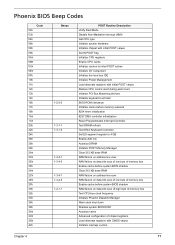
... Load alternate registers with initial POST values Restore CPU control word during warm boot Initialize PCI Bus Mastering devices Initialize keyboard controller BIOS ROM checksum Initialize cache before memory autosize 8254 timer initialization 8237 DMA controller initialization Reset Programmable Interrupt Controller Test DRAM refresh Test ... RAM failure on address line xxxx RAM failure on data bits xxxx of low byte of memory bus Enable cache before system BIOS shadow RAM failure on data bits xxxx of high byte of memory bus Test CPU bus-clock frequency Initialize Phoenix Dispatch Manager ...
... Load alternate registers with initial POST values Restore CPU control word during warm boot Initialize PCI Bus Mastering devices Initialize keyboard controller BIOS ROM checksum Initialize cache before memory autosize 8254 timer initialization 8237 DMA controller initialization Reset Programmable Interrupt Controller Test DRAM refresh Test ... RAM failure on address line xxxx RAM failure on data bits xxxx of low byte of memory bus Enable cache before system BIOS shadow RAM failure on data bits xxxx of high byte of memory bus Test CPU bus-clock frequency Initialize Phoenix Dispatch Manager ...
Service Guide
Page 86
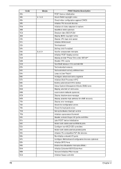
...video configuration against CMOS Initialize PCI bus and devices Initialize all video adapters in system QuietBoot start (optional) Shadow video BIOS ROM Display BIOS copyright notice Display CPU type and speed Initialize EISA board Test keyboard Set key click if enabled Test for unexpected ... ports Initialize PC-compatible PnP ISA devices Re-initialize onboard I/O ports Configure Motherboard Configurable Devices (optional) Initialize BIOS Area Enable Non-Maskable Interrupts (NMIs) Initialize Extended BIOS Data Area Test and initialize PS/2 mouse Initialize floppy controller 78 Chapter 4
...video configuration against CMOS Initialize PCI bus and devices Initialize all video adapters in system QuietBoot start (optional) Shadow video BIOS ROM Display BIOS copyright notice Display CPU type and speed Initialize EISA board Test keyboard Set key click if enabled Test for unexpected ... ports Initialize PC-compatible PnP ISA devices Re-initialize onboard I/O ports Configure Motherboard Configurable Devices (optional) Initialize BIOS Area Enable Non-Maskable Interrupts (NMIs) Initialize Extended BIOS Data Area Test and initialize PS/2 mouse Initialize floppy controller 78 Chapter 4
Service Guide
Page 88
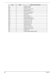
Code E1h E2h E3h E4h E5h E6h E7h E8h E9h EAh EBh ECh EDh EEh EFh F0h F1h F2h F3h Beeps POST Routine Description Initialize the bridge Initialize the CPU Initialize the system timer Initialize system I/O Check force recovery boot Checksum BIOS ROM Go to BIOS Set Huge Segment Initialize Multi Processor Initialize OEM special code Initialize PIC and DMA Initialize Memory type Initialize Memory size Shadow Boot Block System memory test Initialize interrupt vectors Initialize Run Time Clock Initialize video Initialize System Management Mode 80 Chapter 4
Code E1h E2h E3h E4h E5h E6h E7h E8h E9h EAh EBh ECh EDh EEh EFh F0h F1h F2h F3h Beeps POST Routine Description Initialize the bridge Initialize the CPU Initialize the system timer Initialize system I/O Check force recovery boot Checksum BIOS ROM Go to BIOS Set Huge Segment Initialize Multi Processor Initialize OEM special code Initialize PIC and DMA Initialize Memory type Initialize Memory size Shadow Boot Block System memory test Initialize interrupt vectors Initialize Run Time Clock Initialize video Initialize System Management Mode 80 Chapter 4


