Aspire 6935 Series Quick Guide
Page 10
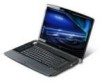
Note: Do not cover or obstruct the opening of the fan. 4 Battery bay Houses the computer's battery pack. 5 Battery release latch Releases the battery for removal. 6 Battery lock Locks the battery in position. 10 Base view English # Icon Item Description 1 Memory compartment Houses the computer's main memory. 2 Hard disk bay Houses the computer's hard disk (secured with screws). 3 Ventilation slots and Enable the computer to stay cool, even after cooling fan prolonged use.
Note: Do not cover or obstruct the opening of the fan. 4 Battery bay Houses the computer's battery pack. 5 Battery release latch Releases the battery for removal. 6 Battery lock Locks the battery in position. 10 Base view English # Icon Item Description 1 Memory compartment Houses the computer's main memory. 2 Hard disk bay Houses the computer's hard disk (secured with screws). 3 Ventilation slots and Enable the computer to stay cool, even after cooling fan prolonged use.
Service Guide
Page 7
...18 The Euro symbol 18 The US dollar sign 18 Acer Empowering Technology 19 Empowering Technology password 20 Acer eAudio Management 21 Acer ePower Management 22 Acer eDataSecurity Management (for selected models 24 Acer eRecovery Management 26 Acer eSettings Management 28 Using the System Utilities 30 Hardware ... unlock Utility 52 Machine Disassembly and Replacement 53 General Information 54 Before You Begin 54 Disassembly Procedure Flowchard 55 Removing the Battery Pack 57 Removing HDD/Wirless Cover/RAM Module/Wireless LAN Card/TV Tunder Card/ System Fan/ Thermal Module/CPU/ODD...
...18 The Euro symbol 18 The US dollar sign 18 Acer Empowering Technology 19 Empowering Technology password 20 Acer eAudio Management 21 Acer ePower Management 22 Acer eDataSecurity Management (for selected models 24 Acer eRecovery Management 26 Acer eSettings Management 28 Using the System Utilities 30 Hardware ... unlock Utility 52 Machine Disassembly and Replacement 53 General Information 54 Before You Begin 54 Disassembly Procedure Flowchard 55 Removing the Battery Pack 57 Removing HDD/Wirless Cover/RAM Module/Wireless LAN Card/TV Tunder Card/ System Fan/ Thermal Module/CPU/ODD...
Service Guide
Page 19
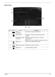
Base View No. Note: Do not cover or obstruct the opening of the fan. 4 Battery bay Houses the computer's battery pack. 5 Battery release latch Releases the battery for removal. 6 Battery lock Locks the battery in position. Icon Item 1 Memory compartment Description Houses the computer's main memory. 2 Hard disk bay Houses the computer's hard disk (secured with screws). 3 Ventilation slots and Enable the computer to stay cool, even after cooling fan prolonged use. Chapter 1 11
Base View No. Note: Do not cover or obstruct the opening of the fan. 4 Battery bay Houses the computer's battery pack. 5 Battery release latch Releases the battery for removal. 6 Battery lock Locks the battery in position. Icon Item 1 Memory compartment Description Houses the computer's main memory. 2 Hard disk bay Houses the computer's hard disk (secured with screws). 3 Ventilation slots and Enable the computer to stay cool, even after cooling fan prolonged use. Chapter 1 11
Service Guide
Page 20
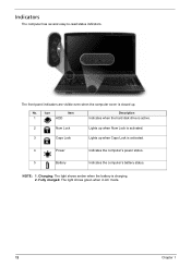
... Lock Lights up when Num Lock is activated. 3 Caps Lock Lights up . Charging: The light shows amber when the battery is activated. 4 Power Indicates the computer's power status. 5 Battery Indicates the computer's battery status. The front panel indicators are visible even when the computer cover is closed up when Caps Lock is charging...
... Lock Lights up when Num Lock is activated. 3 Caps Lock Lights up . Charging: The light shows amber when the battery is activated. 4 Power Indicates the computer's power status. 5 Battery Indicates the computer's battery status. The front panel indicators are visible even when the computer cover is closed up when Caps Lock is charging...
Service Guide
Page 27
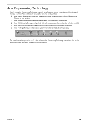
... access frequently used functions and manage your system. ‰ Acer ePower Management optimizes battery usage via customizable power plans. ‰ Acer eDataSecurity Management protects data with passwords and encryption (for selected models). ‰ Acer eRecovery Management backs up and recovers data flexibly, reliablyand completely. ‰ Acer eSettings Management accesses system information and adjusts settings easily...
... access frequently used functions and manage your system. ‰ Acer ePower Management optimizes battery usage via customizable power plans. ‰ Acer eDataSecurity Management protects data with passwords and encryption (for selected models). ‰ Acer eRecovery Management backs up and recovers data flexibly, reliablyand completely. ‰ Acer eSettings Management accesses system information and adjusts settings easily...
Service Guide
Page 30
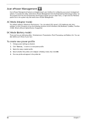
...define up to three of your power management options. Select whether this utility, select Acer ePower Management from the Empowering Technology toolbar, run the program from the Acer Empowering Technology program group in Start menu, or right-click the Windows power icon...adjust CPU speed, LCD brightness and other settings, or click on buttons to a new power profile. 3. Acer ePower Management Acer ePower Management features a straightforward user interface for Adapter or Battery mode, then click OK. 5. Click "Save as desired. 2. Entertainment, Presentation, Word Processing, and...
...define up to three of your power management options. Select whether this utility, select Acer ePower Management from the Empowering Technology toolbar, run the program from the Acer Empowering Technology program group in Start menu, or right-click the Windows power icon...adjust CPU speed, LCD brightness and other settings, or click on buttons to a new power profile. 3. Acer ePower Management Acer ePower Management features a straightforward user interface for Adapter or Battery mode, then click OK. 5. Click "Save as desired. 2. Entertainment, Presentation, Word Processing, and...
Service Guide
Page 31
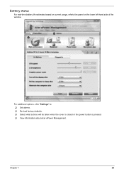
Battery status For real-time battery life estimates based on current usage, referto the panel on the lower left-hand side of the window. Chapter 1 23 For additional options, click "Settings" to: ‰ Set alarms. ‰ Re-load factory defaults. ‰ Select what actions will be taken when the cover is closed or the power button is pressed. ‰ View information about Acer ePower Management.
Battery status For real-time battery life estimates based on current usage, referto the panel on the lower left-hand side of the window. Chapter 1 23 For additional options, click "Settings" to: ‰ Set alarms. ‰ Re-load factory defaults. ‰ Select what actions will be taken when the cover is closed or the power button is pressed. ‰ View information about Acer ePower Management.
Service Guide
Page 46
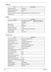
... simultaneously Specification ITE 8512E 88-/89-key Yes Plug USB keyboard to the USB port directly: Yes Battery Item Vendor & Model Name Battery Type Pack capacity Number of battery cell Package configuration Normal voltage Charge voltage Specification BATTERY PACK SANYO LI-ION 8 CELL2.4, 4800MAH BATTRY PACK SONY LIION 8CELL2.4, 4800MAH Li-ion 4800 mAH...
... simultaneously Specification ITE 8512E 88-/89-key Yes Plug USB keyboard to the USB port directly: Yes Battery Item Vendor & Model Name Battery Type Pack capacity Number of battery cell Package configuration Normal voltage Charge voltage Specification BATTERY PACK SANYO LI-ION 8 CELL2.4, 4800MAH BATTRY PACK SONY LIION 8CELL2.4, 4800MAH Li-ion 4800 mAH...
Service Guide
Page 61
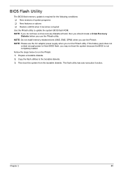
... steps below to finish BIOS flash, you run the Phlash. 1. Copy the flash utilities to update the system BIOS flash ROM. Chapter 2 51 If the battery pack does not contain enough power to run the Phlash utility. Then boot the system from the bootable diskette. NOTE: Do not install memory-related...
... steps below to finish BIOS flash, you run the Phlash. 1. Copy the flash utilities to update the system BIOS flash ROM. Chapter 2 51 If the battery pack does not contain enough power to run the Phlash utility. Then boot the system from the bootable diskette. NOTE: Do not install memory-related...
Service Guide
Page 64
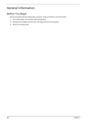
Unplug the AC adapter and all peripherals. 2. General Information Before You Begin Before proceeding with the disassembly procedure, make sure that you do the following: 1. Turn off the power to the system and all power and signal cables from the system. 3. Remove the battery pack. 54 Chapter 3
Unplug the AC adapter and all peripherals. 2. General Information Before You Begin Before proceeding with the disassembly procedure, make sure that you do the following: 1. Turn off the power to the system and all power and signal cables from the system. 3. Remove the battery pack. 54 Chapter 3
Service Guide
Page 67
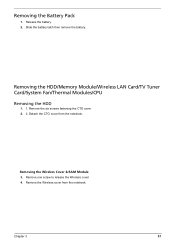
Removing the Wireless Cover & RAM Module 3. Chapter 3 57 Slide the battery latch then remove the battery. Detach the CTO cover from the notebook. Release the battery. 2. Remove the Wireless cover from the notebook.. Removing the Battery Pack 1. Remove the six screws fastening the CTO cover 2. 2. Remove one screw to release the Wireless cover 4. Removing the HDD/Memory Module/Wireless LAN Card/TV Tuner Card/System Fan/Thermal Modules/CPU Removing the HDD 1. 1.
Removing the Wireless Cover & RAM Module 3. Chapter 3 57 Slide the battery latch then remove the battery. Detach the CTO cover from the notebook. Release the battery. 2. Remove the Wireless cover from the notebook.. Removing the Battery Pack 1. Remove the six screws fastening the CTO cover 2. 2. Remove one screw to release the Wireless cover 4. Removing the HDD/Memory Module/Wireless LAN Card/TV Tuner Card/System Fan/Thermal Modules/CPU Removing the HDD 1. 1.
Service Guide
Page 79
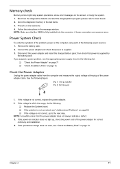
...defect. 3. If the operational charge does not work, see "Undetermined Problems" on page 86. ‰ If the voltage is not corrected, see "Check the Battery Pack" on page 72. Chapter 4 71 Press F2 in the message window. NOTE: Make sure that power is not correct, replace the power adapter. 2....diagnostic memory in the following figure: Pin 1: +19 to main board. 2. Connect the power adapter and check that the DIMM is supplied by the battery pack. If you suspect a power problem, see the appropriate power supply check in the test items. 3. Go to the next step. See the...
...defect. 3. If the operational charge does not work, see "Undetermined Problems" on page 86. ‰ If the voltage is not corrected, see "Check the Battery Pack" on page 72. Chapter 4 71 Press F2 in the message window. NOTE: Make sure that power is not correct, replace the power adapter. 2....diagnostic memory in the following figure: Pin 1: +19 to main board. 2. Connect the power adapter and check that the DIMM is supplied by the battery pack. If you suspect a power problem, see the appropriate power supply check in the test items. 3. Go to the next step. See the...
Service Guide
Page 80
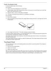
... actions are necessary if the pointer movement stops in the screen for Current Power Source and Total Battery Power Remaining are correct. 3. This helps you use a discharged battery pack or a battery pack that if the parameters shown in a short period of the total power remaining when installed in... is still less than 50% of time. 72 Chapter 4 Reconnect the touchpad cables. 2. Power off the computer. 2. Check the Battery Pack To check the battery pack, do the following actions one at a time to room temperature. Replace the system board. If the voltage is applied to the...
... actions are necessary if the pointer movement stops in the screen for Current Power Source and Total Battery Power Remaining are correct. 3. This helps you use a discharged battery pack or a battery pack that if the parameters shown in a short period of the total power remaining when installed in... is still less than 50% of time. 72 Chapter 4 Reconnect the touchpad cables. 2. Power off the computer. 2. Check the Battery Pack To check the battery pack, do the following actions one at a time to room temperature. Replace the system board. If the voltage is applied to the...
Service Guide
Page 82
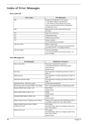
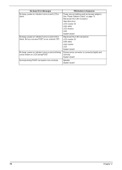
...010 070 071 072 110 Error Message List Error Messages Failure Fixed Disk Stuck Key Keyboard error Keyboard Controller Failed Keyboard locked - Battery critical LOW In this situation BIOS will show message. "Load Default Settings" in BIOS Setup Utility. see "Keyboard or Auxiliary ... not match CMOS - Default configuration used System timer error 74 Error Messages Equipment Configuration Error causes: 1. Real Time Clock Error CMOS Battery Bad CMOS Checksum Error System disabled Incorrect password is dead - CPU BIOS Update Code Mismatch. 2. Hard disk drive System board see ...
...010 070 071 072 110 Error Message List Error Messages Failure Fixed Disk Stuck Key Keyboard error Keyboard Controller Failed Keyboard locked - Battery critical LOW In this situation BIOS will show message. "Load Default Settings" in BIOS Setup Utility. see "Keyboard or Auxiliary ... not match CMOS - Default configuration used System timer error 74 Error Messages Equipment Configuration Error causes: 1. Real Time Clock Error CMOS Battery Bad CMOS Checksum Error System disabled Incorrect password is dead - CPU BIOS Update Code Mismatch. 2. Hard disk drive System board see ...
Service Guide
Page 83
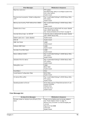
.... System board System board DIMM System board DIMM System board DIMM System board Run "Load Default Settings" in BIOS Setup Utility. RTC battery System board Run "Load Default Settings" in BIOS Setup Utility. Diskette drive Hard disk drive System board Error Message List No beep Error...the DIMM LED board System board Chapter 4 75 Memory size found FRU/Action in BIOS Setup Utility. RTC battery System board Run "Load Default Settings" in Sequence Power source (battery pack and power adapter). See "External Diskette Drive Check" on indicator turns off and LCD is defined with...
.... System board System board DIMM System board DIMM System board DIMM System board Run "Load Default Settings" in BIOS Setup Utility. RTC battery System board Run "Load Default Settings" in BIOS Setup Utility. Diskette drive Hard disk drive System board Error Message List No beep Error...the DIMM LED board System board Chapter 4 75 Memory size found FRU/Action in BIOS Setup Utility. RTC battery System board Run "Load Default Settings" in Sequence Power source (battery pack and power adapter). See "External Diskette Drive Check" on indicator turns off and LCD is defined with...
Service Guide
Page 84
... on and LCD is blank. No beep, power-on indicator turns on and LCD is connected tightly and correctly. FRU/Action in Sequence Power source (battery pack and power adapter). But you can see POST on LCD during POST but system runs correctly. No beep, power-on indicator turns on and...
... on and LCD is blank. No beep, power-on indicator turns on and LCD is connected tightly and correctly. FRU/Action in Sequence Power source (battery pack and power adapter). But you can see POST on LCD during POST but system runs correctly. No beep, power-on indicator turns on and...
Service Guide
Page 90
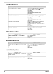
.... PCMCIA slot pin is damaged. Hold and press the power switch for more than 4 seconds. Action in Sequence Power source (battery pack and power adapter). Action in Sequence PCMCIA slot assembly System board PCMCIA slot assembly Memory-Related Symptoms Symptom / Error Memory count... (size) appears different from the computer. Battery pack System board PCMCIA-Related Symptoms Symptom / Error System cannot detect the PC Card (PCMCIA) . Action in Sequence Audio driver ...
.... PCMCIA slot pin is damaged. Hold and press the power switch for more than 4 seconds. Action in Sequence Power source (battery pack and power adapter). Action in Sequence PCMCIA slot assembly System board PCMCIA slot assembly Memory-Related Symptoms Symptom / Error Memory count... (size) appears different from the computer. Battery pack System board PCMCIA-Related Symptoms Symptom / Error System cannot detect the PC Card (PCMCIA) . Action in Sequence Audio driver ...
Service Guide
Page 91
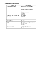
...board Hard disk connection board Hard disk drive System board LCD cover switch System board Remove battery pack and let it cool for 2 hours. Refresh battery (continue use battery until power off, then charge battery). The system doesn't resume from standby mode after closing the LCD. Hard disk connection... resume from hibernation mode. Action in Windows doesn't go higher than 90%. The system doesn't enter standby mode after opening the LCD. Battery fuel gauge in Sequence Keyboard (if control is from the keyboard) Hard disk drive System board Press Fn+o and see if the computer enters...
...board Hard disk connection board Hard disk drive System board LCD cover switch System board Remove battery pack and let it cool for 2 hours. Refresh battery (continue use battery until power off, then charge battery). The system doesn't resume from standby mode after closing the LCD. Hard disk connection... resume from hibernation mode. Action in Windows doesn't go higher than 90%. The system doesn't enter standby mode after opening the LCD. Battery fuel gauge in Sequence Keyboard (if control is from the keyboard) Hard disk drive System board Press Fn+o and see if the computer enters...
Service Guide
Page 94
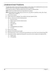
... of the following FRU one at a time. Power-off the computer. 2. If the problem remains, replace the following devices: ‰ Non-Acer devices ‰ Printer, mouse, and other external devices ‰ Battery pack ‰ Hard disk drive ‰ DIMM ‰ CD-ROM/Diskette drive Module ‰ PC Cards 4. Do not replace a non...
... of the following FRU one at a time. Power-off the computer. 2. If the problem remains, replace the following devices: ‰ Non-Acer devices ‰ Printer, mouse, and other external devices ‰ Battery pack ‰ Hard disk drive ‰ DIMM ‰ CD-ROM/Diskette drive Module ‰ PC Cards 4. Do not replace a non...
Service Guide
Page 117
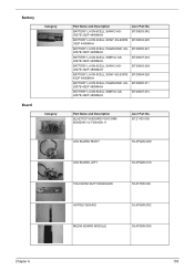
...-ION 6CELL PANASONIC AS2007B 3S2P 4400MAH BATTERY LI-ION 6CELL SIMPLO AS2007B 3S2P 4400MAH BATTERY LI-ION 8CELL SANYO AS2007B 4S2P 4800MAH BATTERY LI-ION 8CELL SONY AS-2007B 4S2P 4800MAH BATTERY LI-ION 8CELL PANASONIC AS2007B 4S2P 4800MAH BATTERY LI-ION 8CELL SIMPLO AS2007B 4S2P 4800MAH Acer Part No. BT.00603.042 BT....00604.025 BT.00605.021 BT.00607.016 BT.00803.024 BT.00804.020 BT.00805.011 BT.00807.015 Part Name and Description BLUETOOTH BOARD FOXCONN BCM2045 V2 T60H928.11 Acer Part No.
...-ION 6CELL PANASONIC AS2007B 3S2P 4400MAH BATTERY LI-ION 6CELL SIMPLO AS2007B 3S2P 4400MAH BATTERY LI-ION 8CELL SANYO AS2007B 4S2P 4800MAH BATTERY LI-ION 8CELL SONY AS-2007B 4S2P 4800MAH BATTERY LI-ION 8CELL PANASONIC AS2007B 4S2P 4800MAH BATTERY LI-ION 8CELL SIMPLO AS2007B 4S2P 4800MAH Acer Part No. BT.00603.042 BT....00604.025 BT.00605.021 BT.00607.016 BT.00803.024 BT.00804.020 BT.00805.011 BT.00807.015 Part Name and Description BLUETOOTH BOARD FOXCONN BCM2045 V2 T60H928.11 Acer Part No.


