User Manual
Page 3
... Specifications 6 1.3 Motherboard Layout 9 1.4 ASRock I/O PlusTM 10 2 Installation 11 Pre-installation Precautions 11 2.1 CPU Installation 12 2.2 Installation of CPU Fan and Heatsink 12 2.3 Installation of Memory Modules (DIMM 13 2.4 Expansion Slots (PCI, AGP, and AMR Slots 14 2.5 Jumpers Setup 15 2.6 Onboard Headers and Connectors 16 2.7 Serial ATA (SATA) Hard Disks Installation 19 2.8 Untied Overclocking Technology 19 3 BIOS SETUP UTILITY 20 3.1 Introduction 20 3.1.1 BIOS Menu Bar 20 3.1.2 Navigation Keys 21 3.2 Main Screen 21 3.3 Advanced Screen 21 3.3.1 CPU Configuration...
... Specifications 6 1.3 Motherboard Layout 9 1.4 ASRock I/O PlusTM 10 2 Installation 11 Pre-installation Precautions 11 2.1 CPU Installation 12 2.2 Installation of CPU Fan and Heatsink 12 2.3 Installation of Memory Modules (DIMM 13 2.4 Expansion Slots (PCI, AGP, and AMR Slots 14 2.5 Jumpers Setup 15 2.6 Onboard Headers and Connectors 16 2.7 Serial ATA (SATA) Hard Disks Installation 19 2.8 Untied Overclocking Technology 19 3 BIOS SETUP UTILITY 20 3.1 Introduction 20 3.1.1 BIOS Menu Bar 20 3.1.2 Navigation Keys 21 3.2 Main Screen 21 3.3 Advanced Screen 21 3.3.1 CPU Configuration...
User Manual
Page 7
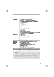
Front panel audio connector - 2 x USB 2.0 headers (support 4 USB 2.0 ports; 2 of your own risk and expense. Drivers, Utilities, AntiVirus Software (Trial Version) - Chassis Temperature Sensing - Chassis Fan Tachometer - Voltage Monitoring: +12V, +5V, +3.3V, Vcore - FCC, CE, WHQL WARNING Please realize that there is a certain risk involved with USB4_5) (see CAUTION 8) - 4Mb AMI BIOS - CD in the BIOS, applying Untied Overclocking Technology, or using the thirdparty overclocking tools. ACPI 1.1 Compliance Wake Up Events - CPU Temperature Sensing - Microsoft® Windows&#...
Front panel audio connector - 2 x USB 2.0 headers (support 4 USB 2.0 ports; 2 of your own risk and expense. Drivers, Utilities, AntiVirus Software (Trial Version) - Chassis Temperature Sensing - Chassis Fan Tachometer - Voltage Monitoring: +12V, +5V, +3.3V, Vcore - FCC, CE, WHQL WARNING Please realize that there is a certain risk involved with USB4_5) (see CAUTION 8) - 4Mb AMI BIOS - CD in the BIOS, applying Untied Overclocking Technology, or using the thirdparty overclocking tools. ACPI 1.1 Compliance Wake Up Events - CPU Temperature Sensing - Microsoft® Windows&#...
User Manual
Page 9
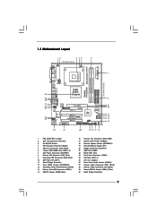
...184-pin DDR DIMM Slots (DDR1- 2) 7 ATX Power Connector (ATXPWR1) 8 Primary IDE Connector (IDE1, Blue) 9 Secondary IDE Connector (IDE2, Black) 10 AGP Slot (1.5V_AGP1) 11 South Bridge Controller 12 Clear CMOS Jumper (CLRCMOS0) 13 Secondary Serial ATA Connector (SATA2) 14 Primary Serial ATA Connector (SATA1) 15 USB 2.0 Header (USB67, Blue) 16 Chassis Fan Connector (CHA_FAN1) 17 System Panel Header (PANEL1) 18 Chassis Speaker Header (SPEAKER 1) 19 Infrared Module Header (IR1) 20 Floppy Connector (FLOPPY1) 21 AMR Slot (AMR1) 22 BIOS FWH Chip 23 Serial Port Connector (COM1) 24 PCI Slots...
...184-pin DDR DIMM Slots (DDR1- 2) 7 ATX Power Connector (ATXPWR1) 8 Primary IDE Connector (IDE1, Blue) 9 Secondary IDE Connector (IDE2, Black) 10 AGP Slot (1.5V_AGP1) 11 South Bridge Controller 12 Clear CMOS Jumper (CLRCMOS0) 13 Secondary Serial ATA Connector (SATA2) 14 Primary Serial ATA Connector (SATA1) 15 USB 2.0 Header (USB67, Blue) 16 Chassis Fan Connector (CHA_FAN1) 17 System Panel Header (PANEL1) 18 Chassis Speaker Header (SPEAKER 1) 19 Infrared Module Header (IR1) 20 Floppy Connector (FLOPPY1) 21 AMR Slot (AMR1) 22 BIOS FWH Chip 23 Serial Port Connector (COM1) 24 PCI Slots...
User Manual
Page 17
... optional wireless transmitting and receiving infrared module. These connectors allow you to receive stereo audio input from sound sources such as a CD-ROM, DVD-ROM, TV tuner card, or MPEG card. L GND A U D - If those USB 2.0 ports on ASRock I/O PlusTM. When using the front panel USB ports by attaching the front panel USB cable to this USB 2.0 header is an interface for front panel audio cable that allows convenient connection and control of the power supply. Front Panel AC'97 Audio Header (8-pin...
... optional wireless transmitting and receiving infrared module. These connectors allow you to receive stereo audio input from sound sources such as a CD-ROM, DVD-ROM, TV tuner card, or MPEG card. L GND A U D - If those USB 2.0 ports on ASRock I/O PlusTM. When using the front panel USB ports by attaching the front panel USB cable to this USB 2.0 header is an interface for front panel audio cable that allows convenient connection and control of the power supply. Front Panel AC'97 Audio Header (8-pin...
User Manual
Page 19
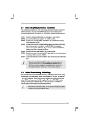
... mode so that supports Serial ATA (SATA) hard disks. Before you to the primary SATA hard disk. You may install SATA hard disks on page 27. 2.8 Untied Overclocking Technology This motherboard supports Untied Overclocking Technology, which will guide you install OS into the drive bays of your chassis. You may set "CPU Host Frequency" option of BIOS setup to the condition of your system. For the configuration details, please refer to the motherboard's primary SATA connector (SATA1). STEP 6: Connect one end of the SATA data cable...
... mode so that supports Serial ATA (SATA) hard disks. Before you to the primary SATA hard disk. You may install SATA hard disks on page 27. 2.8 Untied Overclocking Technology This motherboard supports Untied Overclocking Technology, which will guide you install OS into the drive bays of your chassis. You may set "CPU Host Frequency" option of BIOS setup to the condition of your system. For the configuration details, please refer to the motherboard's primary SATA connector (SATA1). STEP 6: Connect one end of the SATA data cable...
User Manual
Page 20
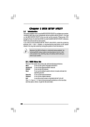
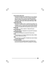
... updated, the following selections: Main To set up the system time/date information Advanced To set up the advanced BIOS features PCIPnP To set up the PCI features Boot To set up the default system device to locate and load the Operating System Security To set up the security features Chipset To set up the computer. Chapter 3 BIOS SETUP UTILITY 3.1 Introduction This section explains how to use the BIOS SETUP UTILITY to configure your screen. 3.1.1 BIOS Menu...
... updated, the following selections: Main To set up the system time/date information Advanced To set up the advanced BIOS features PCIPnP To set up the PCI features Boot To set up the default system device to locate and load the Operating System Security To set up the security features Chipset To set up the computer. Chapter 3 BIOS SETUP UTILITY 3.1 Introduction This section explains how to use the BIOS SETUP UTILITY to configure your screen. 3.1.1 BIOS Menu...
User Manual
Page 22
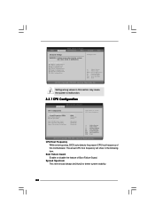
... in this motherboard. CPU Host Frequency While entering setup, BIOS auto detects the present CPU host frequency of Boot Failure Guard. CPU Configuration Chipset Configuration ACPI Configuration IDE Configuration PCIPnP Configuration Floppy Configuration SuperIO Configuration USB Configuration Configure CPU Select Screen Select Item Enter Go to Sub Screen F1 General Help F9 Load Defaults F10 Save and Exit ESC Exit v02.54 (C) Copyright 1985-2003, American Megatrends, Inc. BIOS SETUP UTILITY Main Advanced H/W Monitor Boot Security Exit Advanced Settings WARNING : Setting wrong values...
... in this motherboard. CPU Host Frequency While entering setup, BIOS auto detects the present CPU host frequency of Boot Failure Guard. CPU Configuration Chipset Configuration ACPI Configuration IDE Configuration PCIPnP Configuration Floppy Configuration SuperIO Configuration USB Configuration Configure CPU Select Screen Select Item Enter Go to Sub Screen F1 General Help F9 Load Defaults F10 Save and Exit ESC Exit v02.54 (C) Copyright 1985-2003, American Megatrends, Inc. BIOS SETUP UTILITY Main Advanced H/W Monitor Boot Security Exit Advanced Settings WARNING : Setting wrong values...
User Manual
Page 25
... graphics memory. Configura tion options: [High], and [Low]. Configuration options: [Auto], [Enabled, 1MB], [Enabled, 4MB], [Enabled, 8MB], [Enabled, 16MB] and [Enabled, 32MB]. Configuration options: [High], [Low], and [Auto]. This allows you to leave this motherboard. If larger size of share memory is recommended to select the size of the PCI memory address range used for onboard VGA. ICH Thermal Throttling You may select [Auto] or [Disabled] to adjust ICH southbridge internal thermal control mechanism to set VDDQ. OnBoard AC'97 Audio Select [Auto], [Enabled...
... graphics memory. Configura tion options: [High], and [Low]. Configuration options: [Auto], [Enabled, 1MB], [Enabled, 4MB], [Enabled, 8MB], [Enabled, 16MB] and [Enabled, 32MB]. Configuration options: [High], [Low], and [Auto]. This allows you to leave this motherboard. If larger size of share memory is recommended to select the size of the PCI memory address range used for onboard VGA. ICH Thermal Throttling You may select [Auto] or [Disabled] to adjust ICH southbridge internal thermal control mechanism to set VDDQ. OnBoard AC'97 Audio Select [Auto], [Enabled...
User Manual
Page 27
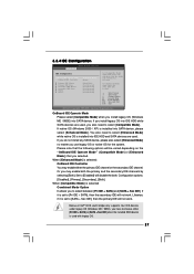
... OS (Windows 2000 / XP) is used . When [Enhanced Mode] is selected: OnBoard IDE Controller You may enable both Legacy OS (MS-DOS, Win Me / 98SE) and SATA device are used, you may enable either [Pri IDE + SATA] or [SATA + Sec IDE] when the installed SATA device is installed into SATA device. Set to choose either the primary IDE channel or the secondary IDE channel. You also need to [Pri IDE + SATA], then the secondary IDE will not work . 3.3.4 IDE Configuration BIOS SETUP UTILITY Advanced IDE Configuration OnBoard IDE Operate Mode OnBoard IDE Controller Primary IDE Master...
... OS (Windows 2000 / XP) is used . When [Enhanced Mode] is selected: OnBoard IDE Controller You may enable both Legacy OS (MS-DOS, Win Me / 98SE) and SATA device are used, you may enable either [Pri IDE + SATA] or [SATA + Sec IDE] when the installed SATA device is installed into SATA device. Set to choose either the primary IDE channel or the secondary IDE channel. You also need to [Pri IDE + SATA], then the secondary IDE will not work . 3.3.4 IDE Configuration BIOS SETUP UTILITY Advanced IDE Configuration OnBoard IDE Operate Mode OnBoard IDE Controller Primary IDE Master...
User Manual
Page 29
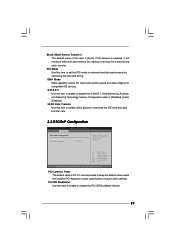
... unless the installed PCI expansion cards' specifications require other settings. PCI Latency Timer The default value is [Auto]. It is enabled, it will enhance hard disk performance by optimizing the hard disk timing. S.M.A.R.T. Block (Multi-Sector Transfer) The default value of PCI clocks for compatible IDE devices. Configuration options: [Disabled], [Auto], [Enabled]. 32-Bit Data Transfer Use this item to maximize the IDE hard disk data transfer rate. 3.3.5 PCIPnP Configuration BIOS SETUP UTILITY Advanced PCI / PnP Configuration PCI Latency Timer PCI IDE BusMaster [32...
... unless the installed PCI expansion cards' specifications require other settings. PCI Latency Timer The default value is [Auto]. It is enabled, it will enhance hard disk performance by optimizing the hard disk timing. S.M.A.R.T. Block (Multi-Sector Transfer) The default value of PCI clocks for compatible IDE devices. Configuration options: [Disabled], [Auto], [Enabled]. 32-Bit Data Transfer Use this item to maximize the IDE hard disk data transfer rate. 3.3.5 PCIPnP Configuration BIOS SETUP UTILITY Advanced PCI / PnP Configuration PCI Latency Timer PCI IDE BusMaster [32...
User Manual
Page 30
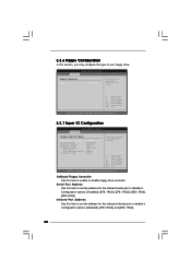
... port or disable it . OnBoard Floppy Controller Use this section, you may configure the type of floppy drive connected to the system. +F1 F9 F10 ESC Select Screen Select Item Change Option General Help Load Defaults Save and Exit Exit v02.54 (C) Copyright 1985-2003, American Megatrends, Inc. 3.3.7 Super IO Configuration BIOS SETUP UTILITY Advanced Configure Super IO Chipset OnBoard Floppy Controller Serial Port Address Infrared Port Address Parallel Port Address Parallel Port Mode EPP Version ECP Mode DMA Channel Parallel Port IRQ [Enabled] [3F8 / IRQ4] [Disabled...
... port or disable it . OnBoard Floppy Controller Use this section, you may configure the type of floppy drive connected to the system. +F1 F9 F10 ESC Select Screen Select Item Change Option General Help Load Defaults Save and Exit Exit v02.54 (C) Copyright 1985-2003, American Megatrends, Inc. 3.3.7 Super IO Configuration BIOS SETUP UTILITY Advanced Configure Super IO Chipset OnBoard Floppy Controller Serial Port Address Infrared Port Address Parallel Port Address Parallel Port Mode EPP Version ECP Mode DMA Channel Parallel Port IRQ [Enabled] [3F8 / IRQ4] [Disabled...
User Manual
Page 31
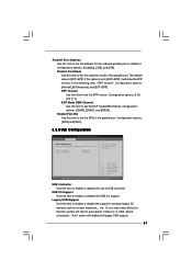
... the parallel port. etc. Parallel Port Address Use this item to [ECP+EPP], it . Configuration options: [1.9] and [1.7]. If this option is set to set the EPP version. Configuration options: [DMA0], [DMA1], and [DMA3]. if there is [ECP+EPP]. Configuration options: [IRQ5] and [IRQ7]. 3.3.8 USB Configuration BIOS SETUP UTILITY Advanced USB Configuration USB Controller USB 2.0 Support Legacy USB Support [Enabled] [Enabled] [Disabled] To enable or disable the onboard USB controllers. +F1 F9 F10 ESC Select Screen Select Item Change Option General Help Load Defaults Save...
... the parallel port. etc. Parallel Port Address Use this item to [ECP+EPP], it . Configuration options: [1.9] and [1.7]. If this option is set to set the EPP version. Configuration options: [DMA0], [DMA1], and [DMA3]. if there is [ECP+EPP]. Configuration options: [IRQ5] and [IRQ7]. 3.3.8 USB Configuration BIOS SETUP UTILITY Advanced USB Configuration USB Controller USB 2.0 Support Legacy USB Support [Enabled] [Enabled] [Disabled] To enable or disable the onboard USB controllers. +F1 F9 F10 ESC Select Screen Select Item Change Option General Help Load Defaults Save...
User Manual
Page 34
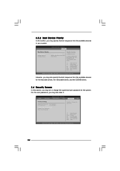
.... BIOS SETUP UTILITY Main Advanced H/W Monitor Boot Security Exit Security Settings Supervisor Password : Not Installed User Password : Not Installed Change Supervisor Password Change User Password Clear User Password Install or Change the password. Select Screen Select Item Enter Change F1 General Help F9 Load Defaults F10 Save and Exit ESC Exit v02.54 (C) Copyright 1985-2003, American Megatrends, Inc. 34 A device enclosed in parenthesis has been disabled in your system. For the user password, you may set or change the supervisor/user password for the hard disk drives...
.... BIOS SETUP UTILITY Main Advanced H/W Monitor Boot Security Exit Security Settings Supervisor Password : Not Installed User Password : Not Installed Change Supervisor Password Change User Password Clear User Password Install or Change the password. Select Screen Select Item Enter Change F1 General Help F9 Load Defaults F10 Save and Exit ESC Exit v02.54 (C) Copyright 1985-2003, American Megatrends, Inc. 34 A device enclosed in parenthesis has been disabled in your system. For the user password, you may set or change the supervisor/user password for the hard disk drives...

User Manual
Page 36
... to contact us or want to know more about ASRock Inc., welcome to your OS documentation for general reference only. Chapter 4 Software Support 4.1 Install Operating System This motherboard supports various Microsoft® Windows® operating systems: 98SE / ME / 2000 / XP. Refer to visit ASRock's website at http://www.asrock.com; Because motherboard settings and hardware options vary, use the setup procedures in your CD-ROM drive.
... to contact us or want to know more about ASRock Inc., welcome to your OS documentation for general reference only. Chapter 4 Software Support 4.1 Install Operating System This motherboard supports various Microsoft® Windows® operating systems: 98SE / ME / 2000 / XP. Refer to visit ASRock's website at http://www.asrock.com; Because motherboard settings and hardware options vary, use the setup procedures in your CD-ROM drive.
Quick Installation Guide
Page 2
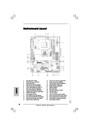
Motherboard Layout English 1 PS2_USB_PWR1 Jumper 2 ATX 12V Connector (ATX12V1) 3 P4-478 CPU Socket 4 CPU Heatsink Retention Module 5 CPU Fan Connector (CPU_FAN1) 6 184-pin DDR DIMM Slots (DDR1- 2) 7 ATX Power Connector (ATXPWR1) 8 Primary IDE Connector (IDE1, Blue) 9 Secondary IDE Connector (IDE2, Black) 10 AGP Slot (1.5V_AGP1) 11 South Bridge Controller 12 Clear CMOS Jumper (CLRCMOS0) 13 Secondary Serial ATA Connector (SATA2) 14 Primary Serial ATA Connector (SATA1) 15 USB 2.0 Header (USB67, Blue) 16 Chassis Fan Connector (CHA_FAN1) 17 System Panel Header (PANEL1) 18 ...
Motherboard Layout English 1 PS2_USB_PWR1 Jumper 2 ATX 12V Connector (ATX12V1) 3 P4-478 CPU Socket 4 CPU Heatsink Retention Module 5 CPU Fan Connector (CPU_FAN1) 6 184-pin DDR DIMM Slots (DDR1- 2) 7 ATX Power Connector (ATXPWR1) 8 Primary IDE Connector (IDE1, Blue) 9 Secondary IDE Connector (IDE2, Black) 10 AGP Slot (1.5V_AGP1) 11 South Bridge Controller 12 Clear CMOS Jumper (CLRCMOS0) 13 Secondary Serial ATA Connector (SATA2) 14 Primary Serial ATA Connector (SATA1) 15 USB 2.0 Header (USB67, Blue) 16 Chassis Fan Connector (CHA_FAN1) 17 System Panel Header (PANEL1) 18 ...
Quick Installation Guide
Page 6
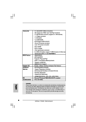
... in the BIOS, applying Untied Overclocking Technology, or using the thirdparty overclocking tools. Voltage Monitoring: +12V, +5V, +3.3V, Vcore - FCC, CE, WHQL WARNING Please realize that there is a certain risk involved with USB4_5) (see CAUTION 8) - 4Mb AMI BIOS - Front panel audio connector - 2 x USB 2.0 headers (support 4 USB 2.0 ports; 2 of your system. Chassis Fan Tachometer - Drivers, Utilities, AntiVirus Software (Trial Version) - CPU/Chassis FAN connector - 20 pin ATX power connector - 4 pin 12V power connector - English 6 ASRock P4i65G Motherboard Overclocking may...
... in the BIOS, applying Untied Overclocking Technology, or using the thirdparty overclocking tools. Voltage Monitoring: +12V, +5V, +3.3V, Vcore - FCC, CE, WHQL WARNING Please realize that there is a certain risk involved with USB4_5) (see CAUTION 8) - 4Mb AMI BIOS - Front panel audio connector - 2 x USB 2.0 headers (support 4 USB 2.0 ports; 2 of your system. Chassis Fan Tachometer - Drivers, Utilities, AntiVirus Software (Trial Version) - CPU/Chassis FAN connector - 20 pin ATX power connector - 4 pin 12V power connector - English 6 ASRock P4i65G Motherboard Overclocking may...
Quick Installation Guide
Page 13
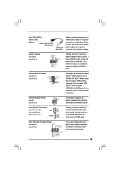
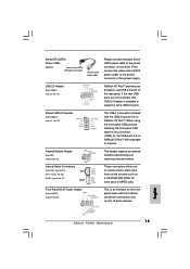
... from sound sources such as a CD-ROM, DVD-ROM, TV tuner card, or MPEG card. Shared USB 2.0 Header (9-pin USB4_5) (see p.2 No. 27) CD1 AUX1 These connectors allow you 6 ready-to-use USB 2.0 ports on ASRock I/O PlusTM will not be able to function. Internal Audio Connectors (4-pin CD1, 4-pin AUX1) (CD1: see p.2 No. 28) (AUX1: see p.2 No. 29) This USB4_5 connector is available to the power connector of the power supply. Serial ATA (SATA) Power Cable (Optional) connect to the SATA HDD power connector connect...
... from sound sources such as a CD-ROM, DVD-ROM, TV tuner card, or MPEG card. Shared USB 2.0 Header (9-pin USB4_5) (see p.2 No. 27) CD1 AUX1 These connectors allow you 6 ready-to-use USB 2.0 ports on ASRock I/O PlusTM will not be able to function. Internal Audio Connectors (4-pin CD1, 4-pin AUX1) (CD1: see p.2 No. 28) (AUX1: see p.2 No. 29) This USB4_5 connector is available to the power connector of the power supply. Serial ATA (SATA) Power Cable (Optional) connect to the SATA HDD power connector connect...
Quick Installation Guide
Page 14
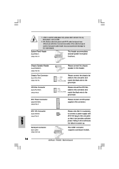
... power. Please connect the CPU fan cable to this header. Failing to do so will cause the failure to the ground pin. This COM1 connector supports a serial port module. 14 ASRock P4i65G Motherboard English Chassis Speaker Header (4-pin SPEAKER 1) (see p.2 No. 18) Chassis Fan Connector (3-pin CHA_FAN1) (see p.2 No. 16) CPU Fan Connector (3-pin CPU_FAN1) (see p.2 No. 5) ATX Power Connector (20-pin ATXPWR1) (see p.2 No. 17) This header accommodates several system front panel functions. Please connect an ATX power supply to this connector and match the black wire to power...
... power. Please connect the CPU fan cable to this header. Failing to do so will cause the failure to the ground pin. This COM1 connector supports a serial port module. 14 ASRock P4i65G Motherboard English Chassis Speaker Header (4-pin SPEAKER 1) (see p.2 No. 18) Chassis Fan Connector (3-pin CHA_FAN1) (see p.2 No. 16) CPU Fan Connector (3-pin CPU_FAN1) (see p.2 No. 5) ATX Power Connector (20-pin ATXPWR1) (see p.2 No. 17) This header accommodates several system front panel functions. Please connect an ATX power supply to this connector and match the black wire to power...
Quick Installation Guide
Page 15
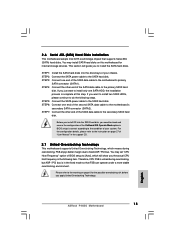
... want to install two SATA HDDs, please continue to the condition of the OnBoard IDE Operate Mode option in the following steps. STEP 1: Install the SATA hard disks into the SATA hard disk, you the actual CPU host frequency in BIOS setup is untied during overclocking, FSB enjoys better margin due to the motherboard's secondary SATA connector (SATA2). STEP 2: Connect the SATA power cable to the SATA hard disk. If you apply Untied Overclocking Technology. 15 ASRock P4i65G Motherboard English You may install SATA hard disks on this...
... want to install two SATA HDDs, please continue to the condition of the OnBoard IDE Operate Mode option in the following steps. STEP 1: Install the SATA hard disks into the SATA hard disk, you the actual CPU host frequency in BIOS setup is untied during overclocking, FSB enjoys better margin due to the motherboard's secondary SATA connector (SATA2). STEP 2: Connect the SATA power cable to the SATA hard disk. If you apply Untied Overclocking Technology. 15 ASRock P4i65G Motherboard English You may install SATA hard disks on this...
Quick Installation Guide
Page 16
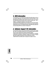
... pressing the reset button on the file "ASSETUP.EXE" from the BIN folder in the Support CD to the User Manual (PDF file) contained in your CD-ROM drive. The Support CD that will display the Main Menu automatically if "AUTORUN" is designed to enter BIOS Setup utility; If you to select among the predetermined choices. The BIOS Setup program is enabled in the Support CD. 4. To begin using the Support CD, insert the...
... pressing the reset button on the file "ASSETUP.EXE" from the BIN folder in the Support CD to the User Manual (PDF file) contained in your CD-ROM drive. The Support CD that will display the Main Menu automatically if "AUTORUN" is designed to enter BIOS Setup utility; If you to select among the predetermined choices. The BIOS Setup program is enabled in the Support CD. 4. To begin using the Support CD, insert the...


