
User Manual
Page 2
...or fitness for identification or explanation and to the owners' benefit, without intent to change without written consent of ASRock Inc. ASRock assumes no event shall ASRock, its directors, officers, employees, or agents be liable for any indirect, special, incidental, or consequential damages...: (1) this device may appear in this manual are used only for a particular purpose. Copyright Notice: No part of this motherboard contains Perchlorate, a toxic substance controlled in Perchlorate Best Management Practices (BMP) regulations passed by the California Legislature. CALIFORNIA, USA ...
...or fitness for identification or explanation and to the owners' benefit, without intent to change without written consent of ASRock Inc. ASRock assumes no event shall ASRock, its directors, officers, employees, or agents be liable for any indirect, special, incidental, or consequential damages...: (1) this device may appear in this manual are used only for a particular purpose. Copyright Notice: No part of this motherboard contains Perchlorate, a toxic substance controlled in Perchlorate Best Management Practices (BMP) regulations passed by the California Legislature. CALIFORNIA, USA ...
User Manual
Page 3
Contents 1 Introduction 5 1.1 Package Contents 5 1.2 Specifications 6 1.3 Motherboard Layout 9 1.4 ASRock I/O PlusTM 10 2 Installation 11 Pre-installation Precautions 11 2.1 CPU Installation 12 2.2 Installation of CPU Fan and Heatsink 12 2.3 Installation of Memory Modules (DIMM 13 2.4 Expansion ...
Contents 1 Introduction 5 1.1 Package Contents 5 1.2 Specifications 6 1.3 Motherboard Layout 9 1.4 ASRock I/O PlusTM 10 2 Installation 11 Pre-installation Precautions 11 2.1 CPU Installation 12 2.2 Installation of CPU Fan and Heatsink 12 2.3 Installation of Memory Modules (DIMM 13 2.4 Expansion ...
User Manual
Page 5
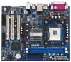
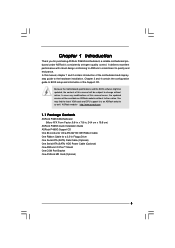
... be updated, the content of this manual occur, the updated version will be available on ASRock website as well. ASRock website http://www.asrock.com 1.1 Package Contents ASRock P4i65G Motherboard (Micro ATX Form Factor: 9.6-in x 7.8-in Floppy Drive One Serial ATA (SATA)... 3.5-in , 24.4 cm x 19.8 cm) ASRock P4i65G Quick Installation Guide ASRock P4i65G Support CD One 80-conductor Ultra ATA 66/100 IDE Ribbon Cable One Ribbon Cable for purchasing ASRock P4i65G motherboard, a reliable motherboard produced under ASRock's consistently stringent quality control. In case any modifications of...
... be updated, the content of this manual occur, the updated version will be available on ASRock website as well. ASRock website http://www.asrock.com 1.1 Package Contents ASRock P4i65G Motherboard (Micro ATX Form Factor: 9.6-in x 7.8-in Floppy Drive One Serial ATA (SATA)... 3.5-in , 24.4 cm x 19.8 cm) ASRock P4i65G Quick Installation Guide ASRock P4i65G Support CD One 80-conductor Ultra ATA 66/100 IDE Ribbon Cable One Ribbon Cable for purchasing ASRock P4i65G motherboard, a reliable motherboard produced under ASRock's consistently stringent quality control. In case any modifications of...
User Manual
Page 8
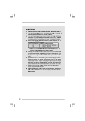
... for proper installation. 4. It may not work properly under Microsoft® Windows® XP SP1 or SP2 / 2000 SP4. Although this motherboard, it back again. CAUTION! 1. Frequencies other than the recommended CPU bus frequencies may cause permanent damage! 8. Please check the table below ... FSB Frequency Memory Support Frequency 800 DDR266, DDR320*, DDR400 533 DDR266, DDR333 * When you adopt a DDR333 memory module. 5. This motherboard supports Dual Channel Memory Technology. About the setting of the system or damage the CPU. 6. Before you install the PC system. 7....
... for proper installation. 4. It may not work properly under Microsoft® Windows® XP SP1 or SP2 / 2000 SP4. Although this motherboard, it back again. CAUTION! 1. Frequencies other than the recommended CPU bus frequencies may cause permanent damage! 8. Please check the table below ... FSB Frequency Memory Support Frequency 800 DDR266, DDR320*, DDR400 533 DDR266, DDR333 * When you adopt a DDR333 memory module. 5. This motherboard supports Dual Channel Memory Technology. About the setting of the system or damage the CPU. 6. Before you install the PC system. 7....
User Manual
Page 9
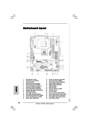
1.3 Motherboard Layout 12 3 45 6 19.8cm (7.8 in) PS2 Mouse 1 PS2_USB_PWR1 PS2 Keyboard CPU_FAN1 VGA1 ATXPWR1 PGA478 PARALLEL PORT 30 29 28 27 26 25 24 23 ... IDE2 IDE1 Intel ICH5 CMOS Battery CLRCMOS0 SATA2 SATA1 USB67 1 IR1 1 CHA_FAN1 PANEL 1 SPEAKER1 PLED PWRBTN 1 1 HDLED RESET 22 21 20 19 18 17 16 P4i65G Prescott800 Dual Channel DDR400 DDR1 (64/72 bit, 184-pin module) DDR2 (64/72 bit, 184-pin module) 24.4cm (9.6 in) 7 8 9 10 11 12 13...
1.3 Motherboard Layout 12 3 45 6 19.8cm (7.8 in) PS2 Mouse 1 PS2_USB_PWR1 PS2 Keyboard CPU_FAN1 VGA1 ATXPWR1 PGA478 PARALLEL PORT 30 29 28 27 26 25 24 23 ... IDE2 IDE1 Intel ICH5 CMOS Battery CLRCMOS0 SATA2 SATA1 USB67 1 IR1 1 CHA_FAN1 PANEL 1 SPEAKER1 PLED PWRBTN 1 1 HDLED RESET 22 21 20 19 18 17 16 P4i65G Prescott800 Dual Channel DDR400 DDR1 (64/72 bit, 184-pin module) DDR2 (64/72 bit, 184-pin module) 24.4cm (9.6 in) 7 8 9 10 11 12 13...
User Manual
Page 11
... touch the ICs. 4. Whenever you install or remove any motherboard settings. 1. Before you install the motherboard, study the configuration of the following precautions before you handle components. 3. To avoid damaging the motherboard components due to use a grounded wrist strap or touch a...that the motherboard fits into it on the carpet or the like. Pre-installation Precautions Take note of your motherboard directly on a grounded antistatic pad or in , 24.4 cm x 19.8 cm) motherboard. Failure to ensure that comes with the component. Chapter 2 Installation P4i65G is ...
... touch the ICs. 4. Whenever you install or remove any motherboard settings. 1. Before you install the motherboard, study the configuration of the following precautions before you handle components. 3. To avoid damaging the motherboard components due to use a grounded wrist strap or touch a...that the motherboard fits into it on the carpet or the like. Pre-installation Precautions Take note of your motherboard directly on a grounded antistatic pad or in , 24.4 cm x 19.8 cm) motherboard. Failure to ensure that comes with the component. Chapter 2 Installation P4i65G is ...
User Manual
Page 12
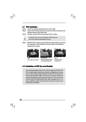
... 3: Match The CPU Marked Corner to The Socket Marked Corner STEP 4: Push Down And Lock The Socket Lever 2.2 Installation of CPU Fan and Heatsink This motherboard adopts 478-pin CPU socket to avoid bending of the CPU fan and the heatsink. 12 For proper installation, please kindly refer to dissipate heat...
... 3: Match The CPU Marked Corner to The Socket Marked Corner STEP 4: Push Down And Lock The Socket Lever 2.2 Installation of CPU Fan and Heatsink This motherboard adopts 478-pin CPU socket to avoid bending of the CPU fan and the heatsink. 12 For proper installation, please kindly refer to dissipate heat...
User Manual
Page 13
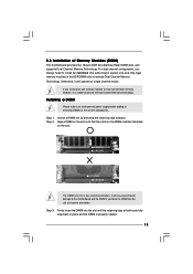
.... Firmly insert the DIMM into the slot at incorrect orientation. Otherwise, it is properly seated. 13 2.3 Installation of Memory Modules (DIMM) This motherboard provides two 184-pin DDR (Double Data Rate) DIMM slots, and supports Dual Channel Memory Technology. For dual channel configuration, you always need to... by pressing the retaining clips outward. It will operate at both ends fully snap back in place and the DIMM is unable to the motherboard and the DIMM if you install only one correct orientation. Step 1. Align a DIMM on the slot such that the notch on the...
.... Firmly insert the DIMM into the slot at incorrect orientation. Otherwise, it is properly seated. 13 2.3 Installation of Memory Modules (DIMM) This motherboard provides two 184-pin DDR (Double Data Rate) DIMM slots, and supports Dual Channel Memory Technology. For dual channel configuration, you always need to... by pressing the retaining clips outward. It will operate at both ends fully snap back in place and the DIMM is unable to the motherboard and the DIMM if you install only one correct orientation. Step 1. Align a DIMM on the slot such that the notch on the...
User Manual
Page 14
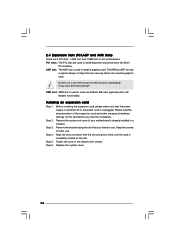
... installing the expansion card, please make necessary hardware settings for later use. Please read the documentation of this motherboard. Do NOT use . Keep the screws for the card before you intend to use a 3.3V AGP card on the AGP slot of the expansion card ... sure that have the 32-bit PCI interface. PCI slots: The PCI slots are 3 PCI slots, 1 AGP slot, and 1 AMR slot on the slot. The ASRock AGP slot has a special design of clasp that you start the installation. Installing an expansion card Step 1. Step 6. Step 4. Fasten the card to install expansion...
... installing the expansion card, please make necessary hardware settings for later use. Please read the documentation of this motherboard. Do NOT use . Keep the screws for the card before you intend to use a 3.3V AGP card on the AGP slot of the expansion card ... sure that have the 32-bit PCI interface. PCI slots: The PCI slots are 3 PCI slots, 1 AGP slot, and 1 AMR slot on the slot. The ASRock AGP slot has a special design of clasp that you start the installation. Installing an expansion card Step 1. Step 6. Step 4. Fasten the card to install expansion...

User Manual
Page 16
...cause permanent damage of your hard disk drive to the primary IDE connector (IDE1, blue) and CD-ROM to the instruction of the motherboard! Placing jumper caps over these headers and connectors. Besides, to the IDE devices 80-conductor ATA 66/100 cable Note: If you use... IDE1, see p.9 No. 8) (39-pin IDE2, see p.9 No. 9) PIN1 IDE1 PIN1 IDE2 connect the blue end connect the black end to the motherboard to optimize compatibility and performance, please connect your IDE device vendor for internal storage devices. Serial ATA (SATA) Data Cable Either end of the connector...
...cause permanent damage of your hard disk drive to the primary IDE connector (IDE1, blue) and CD-ROM to the instruction of the motherboard! Placing jumper caps over these headers and connectors. Besides, to the IDE devices 80-conductor ATA 66/100 cable Note: If you use... IDE1, see p.9 No. 8) (39-pin IDE2, see p.9 No. 9) PIN1 IDE1 PIN1 IDE2 connect the blue end connect the black end to the motherboard to optimize compatibility and performance, please connect your IDE device vendor for internal storage devices. Serial ATA (SATA) Data Cable Either end of the connector...

User Manual
Page 18
... match the black wire to the ground pin. Chassis Fan Connector (3-pin CHA_FAN1) (see p.9 No. 5) GND +12V CPU_FAN_SPEED Please connect a CPU fan cable to this motherboard. CPU Fan Connector (3-pin CPU_FAN1) (see p.9 No. 16) GND +12V CHA_FAN_SPEED Please connect a chassis fan cable to this connector. This COM port header is necessary...
... match the black wire to the ground pin. Chassis Fan Connector (3-pin CHA_FAN1) (see p.9 No. 5) GND +12V CPU_FAN_SPEED Please connect a CPU fan cable to this motherboard. CPU Fan Connector (3-pin CPU_FAN1) (see p.9 No. 16) GND +12V CHA_FAN_SPEED Please connect a chassis fan cable to this connector. This COM port header is necessary...
User Manual
Page 19
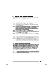
...STEP 4: Connect the other end of your system. Therefore, CPU FSB is untied during overclocking, FSB enjoys better margin due to the motherboard's primary SATA connector (SATA1). If you the actual CPU host frequency in the following steps. You may install SATA hard disks on page... 27. 2.8 Untied Overclocking Technology This motherboard supports Untied Overclocking Technology, which will guide you want to install only one end of BIOS setup to [Auto], which means during ...
...STEP 4: Connect the other end of your system. Therefore, CPU FSB is untied during overclocking, FSB enjoys better margin due to the motherboard's primary SATA connector (SATA1). If you the actual CPU host frequency in the following steps. You may install SATA hard disks on page... 27. 2.8 Untied Overclocking Technology This motherboard supports Untied Overclocking Technology, which will guide you want to install only one end of BIOS setup to [Auto], which means during ...
User Manual
Page 20
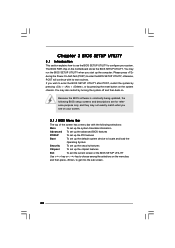
... (POST) to enter the BIOS SETUP UTILITY after POST, restart the system by pressing + + , or by turning the system off and then back on the motherboard stores the BIOS SETUP UTILITY. You may not exactly match what you see on your system. If you start up the chipset features Exit To...
... (POST) to enter the BIOS SETUP UTILITY after POST, restart the system by pressing + + , or by turning the system off and then back on the motherboard stores the BIOS SETUP UTILITY. You may not exactly match what you see on your system. If you start up the chipset features Exit To...
User Manual
Page 22
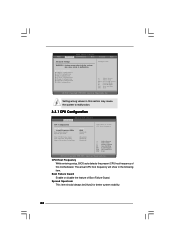
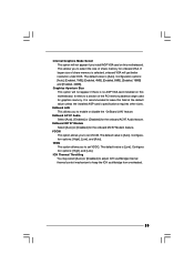
... Floppy Configuration SuperIO Configuration USB Configuration Configure CPU Select Screen Select Item Enter Go to malfunction. The actual CPU host frequency will show in this motherboard. CPU Host Frequency While entering setup, BIOS auto detects the present CPU host frequency of Boot Failure Guard.
... Floppy Configuration SuperIO Configuration USB Configuration Configure CPU Select Screen Select Item Enter Go to malfunction. The actual CPU host frequency will show in this motherboard. CPU Host Frequency While entering setup, BIOS auto detects the present CPU host frequency of Boot Failure Guard.
User Manual
Page 24
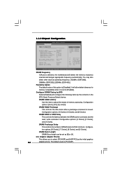
...] DRAM Burst Length [4] Init. tion options: [8 Clocks], [7 Clocks], [6 Clocks], and [5 Clocks]. DRAM RAS# Precharge This controls the idle clocks after a precharge command is selected, the motherboard will allow better tolerance for RAS minimum. DRAM Frequency If [Auto] is issued. It will detect the memory module(s) inserted and assigns appropriate frequency automatically...
...] DRAM Burst Length [4] Init. tion options: [8 Clocks], [7 Clocks], [6 Clocks], and [5 Clocks]. DRAM RAS# Precharge This controls the idle clocks after a precharge command is selected, the motherboard will allow better tolerance for RAS minimum. DRAM Frequency If [Auto] is issued. It will detect the memory module(s) inserted and assigns appropriate frequency automatically...
User Manual
Page 25
OnBoard LAN This allows you install AGP VGA card on this motherboard. OnBoard MC'97 Modem Select [Auto] or [Disabled] for the onboard AC'97 Audio feature. Configuration options: [High], [Low], and [Auto]. The default value is [... allows you to set VDDQ. ICH Thermal Throttling You may select [Auto] or [Disabled] to adjust ICH southbridge internal thermal control mechanism to leave this motherboard. It refers to set VCCM. VDDQ This option allows you to a section of share memory is selected, onboard VGA will not appear if there is...
OnBoard LAN This allows you install AGP VGA card on this motherboard. OnBoard MC'97 Modem Select [Auto] or [Disabled] for the onboard AC'97 Audio feature. Configuration options: [High], [Low], and [Auto]. The default value is [... allows you to set VDDQ. ICH Thermal Throttling You may select [Auto] or [Disabled] to adjust ICH southbridge internal thermal control mechanism to leave this motherboard. It refers to set VCCM. VDDQ This option allows you to a section of share memory is selected, onboard VGA will not appear if there is...

User Manual
Page 32
... Monitoring Screen In this section, it allows you to monitor the status of the hardware on your system, including the parameters of the CPU temperature, motherboard temperature, CPU fan speed, chassis fan speed, and the critical voltage.
... Monitoring Screen In this section, it allows you to monitor the status of the hardware on your system, including the parameters of the CPU temperature, motherboard temperature, CPU fan speed, chassis fan speed, and the critical voltage.

User Manual
Page 36
...The Support CD that came with the motherboard contains necessary drivers and useful utilities that the motherboard supports. Because motherboard settings and hardware options vary, use the setup procedures in the Support CD to visit ASRock's website at http://www.asrock.com; Refer to activate the devices. ...4.2.3 Utilities Menu The Utilities Menu shows the applications software that enhance the motherboard features. 4.2.1 Running The Support CD To begin using ...
...The Support CD that came with the motherboard contains necessary drivers and useful utilities that the motherboard supports. Because motherboard settings and hardware options vary, use the setup procedures in the Support CD to visit ASRock's website at http://www.asrock.com; Refer to activate the devices. ...4.2.3 Utilities Menu The Utilities Menu shows the applications software that enhance the motherboard features. 4.2.1 Running The Support CD To begin using ...
Quick Installation Guide
Page 1
... possibility of such damages arising from any defect or error in the guide or product. All rights reserved. 1 ASRock P4i65G Motherboard English When you discard the Lithium battery in California, USA, please follow the related regulations in Perchlorate Best Management ...Practices (BMP) regulations passed by the California Legislature. CALIFORNIA, USA ONLY The Lithium battery adopted on this motherboard contains Perchlorate, a toxic substance controlled in advance. Copyright Notice: No part of this installation guide may be reproduced, transcribed,...
... possibility of such damages arising from any defect or error in the guide or product. All rights reserved. 1 ASRock P4i65G Motherboard English When you discard the Lithium battery in California, USA, please follow the related regulations in Perchlorate Best Management ...Practices (BMP) regulations passed by the California Legislature. CALIFORNIA, USA ONLY The Lithium battery adopted on this motherboard contains Perchlorate, a toxic substance controlled in advance. Copyright Notice: No part of this installation guide may be reproduced, transcribed,...
Quick Installation Guide
Page 2
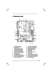
Motherboard Layout English 1 PS2_USB_PWR1 Jumper 2 ATX 12V Connector (ATX12V1) 3 P4-478 CPU Socket 4 CPU Heatsink Retention Module 5 CPU Fan Connector (CPU_FAN1) 6 184-pin DDR DIMM Slots (... Audio Header (AUDIO1) 27 Internal Audio Connector: AUX1 (White) 28 Internal Audio Connector: CD1 (Black) 29 Shared USB 2.0 Header (USB4_5, Blue) 30 North Bridge Controller 2 ASRock P4i65G Motherboard
Motherboard Layout English 1 PS2_USB_PWR1 Jumper 2 ATX 12V Connector (ATX12V1) 3 P4-478 CPU Socket 4 CPU Heatsink Retention Module 5 CPU Fan Connector (CPU_FAN1) 6 184-pin DDR DIMM Slots (... Audio Header (AUDIO1) 27 Internal Audio Connector: AUX1 (White) 28 Internal Audio Connector: CD1 (Black) 29 Shared USB 2.0 Header (USB4_5, Blue) 30 North Bridge Controller 2 ASRock P4i65G Motherboard


