User Manual
Page 6
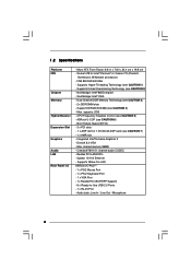
... slot - Support DDR400/333/266 (see CAUTION 5) - Supports Wake-On-LAN ASRock I /O - capacity: 2GB - Integrated Intel® Extreme Graphics 2 - Supports Hyper-Threading Technology (see CAUTION 6) - ASRock U-COP (see CAUTION 1) - 1.2 Specifications Platform CPU Chipset Memory Hybrid Booster Expansion Slot Graphics Audio LAN Rear Panel I /O PlusTM - 1 x PS/2 Mouse Port - 1 x PS/2 Keyboard Port - 1 x VGA Port - 1 x Parallel...
... slot - Support DDR400/333/266 (see CAUTION 5) - Supports Wake-On-LAN ASRock I /O - capacity: 2GB - Integrated Intel® Extreme Graphics 2 - Supports Hyper-Threading Technology (see CAUTION 6) - ASRock U-COP (see CAUTION 1) - 1.2 Specifications Platform CPU Chipset Memory Hybrid Booster Expansion Slot Graphics Audio LAN Rear Panel I /O PlusTM - 1 x PS/2 Mouse Port - 1 x PS/2 Keyboard Port - 1 x VGA Port - 1 x Parallel...
User Manual
Page 7
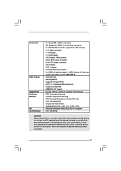
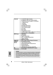
Supports "Plug and Play" - SMBIOS 2.3.1 Support - CPU Fan Tachometer - Microsoft® Windows® 98SE/ME/2000/XP compliant - AMI Legal BIOS - Chassis Fan Tachometer - Front panel audio connector - 2 x USB 2.0 headers (support 4 USB 2.0 ports; 2 of your system. ACPI 1.1 Compliance Wake Up Events - Supports jumperfree - CPU Temperature Sensing - CPU Overheat Shutdown to the ...
Supports "Plug and Play" - SMBIOS 2.3.1 Support - CPU Fan Tachometer - Microsoft® Windows® 98SE/ME/2000/XP compliant - AMI Legal BIOS - Chassis Fan Tachometer - Front panel audio connector - 2 x USB 2.0 headers (support 4 USB 2.0 ports; 2 of your system. ACPI 1.1 Compliance Wake Up Events - Supports jumperfree - CPU Temperature Sensing - CPU Overheat Shutdown to the ...
User Manual
Page 9
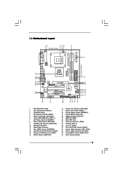
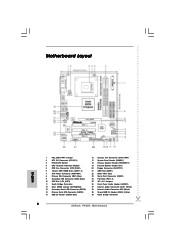
....0 5.1CH PCI 3 FLOPPY1 AMR1 IDE2 IDE1 Intel ICH5 CMOS Battery CLRCMOS0 SATA2 SATA1 USB67 1 IR1 1 CHA_FAN1 PANEL 1 SPEAKER1 PLED PWRBTN 1 1 HDLED RESET 22 21 20 19 18 17 16 P4i65G Prescott800 Dual Channel DDR400 DDR1 (64/72 bit, 184-pin module) DDR2 (64/72 bit, 184-pin module... Secondary Serial ATA Connector (SATA2) 14 Primary Serial ATA Connector (SATA1) 15 USB 2.0 Header (USB67, Blue) 16 Chassis Fan Connector (CHA_FAN1) 17 System Panel Header (PANEL1) 18 Chassis Speaker Header (SPEAKER 1) 19 Infrared Module Header (IR1) 20 Floppy Connector (FLOPPY1) 21 AMR Slot (AMR1) 22 BIOS FWH...
....0 5.1CH PCI 3 FLOPPY1 AMR1 IDE2 IDE1 Intel ICH5 CMOS Battery CLRCMOS0 SATA2 SATA1 USB67 1 IR1 1 CHA_FAN1 PANEL 1 SPEAKER1 PLED PWRBTN 1 1 HDLED RESET 22 21 20 19 18 17 16 P4i65G Prescott800 Dual Channel DDR400 DDR1 (64/72 bit, 184-pin module) DDR2 (64/72 bit, 184-pin module... Secondary Serial ATA Connector (SATA2) 14 Primary Serial ATA Connector (SATA1) 15 USB 2.0 Header (USB67, Blue) 16 Chassis Fan Connector (CHA_FAN1) 17 System Panel Header (PANEL1) 18 Chassis Speaker Header (SPEAKER 1) 19 Infrared Module Header (IR1) 20 Floppy Connector (FLOPPY1) 21 AMR Slot (AMR1) 22 BIOS FWH...

User Manual
Page 15
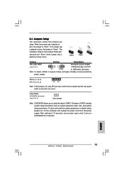
... the jumpers JL1 and JR1 are setup. When the jumper cap is "Short". 2.5 Jumpers Setup The illustration shows how jumpers are short, both the front panel and the rear panel audio connectors can work. To clear and reset the system parameters to enable 2_3 +5VSB (standby) for 5 seconds. 15
... the jumpers JL1 and JR1 are setup. When the jumper cap is "Short". 2.5 Jumpers Setup The illustration shows how jumpers are short, both the front panel and the rear panel audio connectors can work. To clear and reset the system parameters to enable 2_3 +5VSB (standby) for 5 seconds. 15
User Manual
Page 17
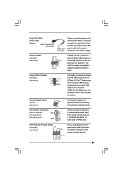
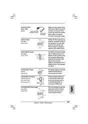
...AUX1 CD-L GND GND CD-R AUX-L GND GND AUX-R This header supports an optional wireless transmitting and receiving infrared module. If those USB 2.0 ports on ASRock I /O panel are not sufficient, this connector (USB4_5), the USB ports 4,5 on each drive. Shared USB 2.0 Header (9-pin USB4_5) (see p.9 No. 15) ... to the SATA HDD power connector connect to the power supply Please connect the black end of SATA power cable to the power connector on ASRock I /O PlusTM accommodates 6 default USB 2.0 ports. USB 2.0 Header (9-pin USB67) (see p.9 No. 29) 1 USB_PWR P-5 P+5 GND USB_PWR P-4 P+4...
...AUX1 CD-L GND GND CD-R AUX-L GND GND AUX-R This header supports an optional wireless transmitting and receiving infrared module. If those USB 2.0 ports on ASRock I /O panel are not sufficient, this connector (USB4_5), the USB ports 4,5 on each drive. Shared USB 2.0 Header (9-pin USB4_5) (see p.9 No. 15) ... to the SATA HDD power connector connect to the power supply Please connect the black end of SATA power cable to the power connector on ASRock I /O PlusTM accommodates 6 default USB 2.0 ports. USB 2.0 Header (9-pin USB67) (see p.9 No. 29) 1 USB_PWR P-5 P+5 GND USB_PWR P-4 P+4...

User Manual
Page 18
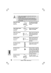
... supply with ATX 12V plug to this connector and match the black wire to the ground pin. HD (Azalia) audio front panel and AC'97 audio front panel have different pin-definition. CPU Fan Connector (3-pin CPU_FAN1) (see p.9 No. 17) PLED+ PLEDPWRBTN# GND 1 DUMMY RESET...# GND HDLEDHDLED+ This header accommodates several system front panel functions. 1. +5VA is used to support a COM port module. Chassis Fan Connector (3-pin CHA_FAN1) (see p.9 No. 23) 18 RRXD1 DDTR#1 DDSR#1 ...
... supply with ATX 12V plug to this connector and match the black wire to the ground pin. HD (Azalia) audio front panel and AC'97 audio front panel have different pin-definition. CPU Fan Connector (3-pin CPU_FAN1) (see p.9 No. 17) PLED+ PLEDPWRBTN# GND 1 DUMMY RESET...# GND HDLEDHDLED+ This header accommodates several system front panel functions. 1. +5VA is used to support a COM port module. Chassis Fan Connector (3-pin CHA_FAN1) (see p.9 No. 23) 18 RRXD1 DDTR#1 DDSR#1 ...
Quick Installation Guide
Page 2
...Serial ATA Connector (SATA2) 14 Primary Serial ATA Connector (SATA1) 15 USB 2.0 Header (USB67, Blue) 16 Chassis Fan Connector (CHA_FAN1) 17 System Panel Header (PANEL1) 18 Chassis Speaker Header (SPEAKER 1) 19 Infrared Module Header (IR1) 20 Floppy Connector (FLOPPY1) 21 AMR Slot (AMR1) 22 ...BIOS FWH Chip 23 Serial Port Connector (COM1) 24 PCI Slots (PCI1- 3) 25 JR1 / JL1 Jumpers 26 Front Panel Audio Header (AUDIO1) 27 Internal Audio Connector: AUX1 (White) 28 Internal Audio Connector: CD1 (Black) 29 Shared USB 2.0 Header (USB4_5, Blue) 30 North Bridge Controller 2 ASRock P4i65G Motherboard
...Serial ATA Connector (SATA2) 14 Primary Serial ATA Connector (SATA1) 15 USB 2.0 Header (USB67, Blue) 16 Chassis Fan Connector (CHA_FAN1) 17 System Panel Header (PANEL1) 18 Chassis Speaker Header (SPEAKER 1) 19 Infrared Module Header (IR1) 20 Floppy Connector (FLOPPY1) 21 AMR Slot (AMR1) 22 ...BIOS FWH Chip 23 Serial Port Connector (COM1) 24 PCI Slots (PCI1- 3) 25 JR1 / JL1 Jumpers 26 Front Panel Audio Header (AUDIO1) 27 Internal Audio Connector: AUX1 (White) 28 Internal Audio Connector: CD1 (Black) 29 Shared USB 2.0 Header (USB4_5, Blue) 30 North Bridge Controller 2 ASRock P4i65G Motherboard
Quick Installation Guide
Page 5
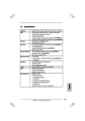
...- Cmedia 9761A 5.1 channel audio CODEC - Audio Jack: Line In / Line Out / Microphone English 5 ASRock P4i65G Motherboard DirectX 8.0 VGA - 1.2 Specifications Platform CPU Chipset Memory Hybrid Booster Expansion Slot Graphics Audio LAN Rear Panel I /O PlusTM - 1 x PS/2 Mouse Port - 1 x PS/2 Keyboard Port - 1 x VGA... Port - 1 x Parallel Port (ECP/EPP Support) - 6 x Ready-to-Use USB 2.0 Ports - 1 x RJ-45 Port - ASRock U-COP (see CAUTION 5) - Supports ...
...- Cmedia 9761A 5.1 channel audio CODEC - Audio Jack: Line In / Line Out / Microphone English 5 ASRock P4i65G Motherboard DirectX 8.0 VGA - 1.2 Specifications Platform CPU Chipset Memory Hybrid Booster Expansion Slot Graphics Audio LAN Rear Panel I /O PlusTM - 1 x PS/2 Mouse Port - 1 x PS/2 Keyboard Port - 1 x VGA... Port - 1 x Parallel Port (ECP/EPP Support) - 6 x Ready-to-Use USB 2.0 Ports - 1 x RJ-45 Port - ASRock U-COP (see CAUTION 5) - Supports ...
Quick Installation Guide
Page 6
... CE, WHQL WARNING Please realize that there is a certain risk involved with USB4_5) (see CAUTION 8) - 4Mb AMI BIOS - English 6 ASRock P4i65G Motherboard Chassis Fan Tachometer - Overclocking may affect your system stability, or even cause damage to Protect CPU Life - CPU/Chassis FAN connector - 20... - Microsoft® Windows® 98SE/ME/2000/XP compliant - We are shared with overclocking, including adjusting the setting in header - Front panel audio connector - 2 x USB 2.0 headers (support 4 USB 2.0 ports; 2 of your own risk and expense. CPU Fan Tachometer - Connector...
... CE, WHQL WARNING Please realize that there is a certain risk involved with USB4_5) (see CAUTION 8) - 4Mb AMI BIOS - English 6 ASRock P4i65G Motherboard Chassis Fan Tachometer - Overclocking may affect your system stability, or even cause damage to Protect CPU Life - CPU/Chassis FAN connector - 20... - Microsoft® Windows® 98SE/ME/2000/XP compliant - We are shared with overclocking, including adjusting the setting in header - Front panel audio connector - 2 x USB 2.0 headers (support 4 USB 2.0 ports; 2 of your own risk and expense. CPU Fan Tachometer - Connector...
Quick Installation Guide
Page 11
English 11 ASRock P4i65G Motherboard Short Open Jumper Setting Description PS2_USB_PWR1 Short pin2, pin3 to clear the data in CMOS includes system setup information such as system password, date, ...) 2-pin jumper Note: CLRCMOS0 allows you to enable (see p.2 No. 25) Note: If the jumpers JL1 and JR1 are short, both the front panel and the rear panel audio connectors can work. To clear and reset the system parameters to short 2 pins on CLRCMOS0 for PS/2 or USB wake up events. The...
English 11 ASRock P4i65G Motherboard Short Open Jumper Setting Description PS2_USB_PWR1 Short pin2, pin3 to clear the data in CMOS includes system setup information such as system password, date, ...) 2-pin jumper Note: CLRCMOS0 allows you to enable (see p.2 No. 25) Note: If the jumpers JL1 and JR1 are short, both the front panel and the rear panel audio connectors can work. To clear and reset the system parameters to short 2 pins on CLRCMOS0 for PS/2 or USB wake up events. The...
Quick Installation Guide
Page 13
English 13 ASRock P4i65G Motherboard Then connect the white end of SATA power cable to the power connector on ASRock I /O PlusTM will not be able to function. Shared USB 2.0 Header (9-pin USB4_5) (see p.2 No. 29) This USB4_5 connector is shared with the USB 2.0 ports... of audio devices. If the rear USB ports are not sufficient, this connector (USB4_5), the USB ports 4,5 on the rear panel. Front Panel AC'97 Audio Header (8-pin AUDIO1) (see p.2 No. 15) ASRock I/O PlusTM provides you to support 2 extra USB 2.0 ports. USB 2.0 Header (9-pin USB67) (see p.2 No. 26) This is ...
English 13 ASRock P4i65G Motherboard Then connect the white end of SATA power cable to the power connector on ASRock I /O PlusTM will not be able to function. Shared USB 2.0 Header (9-pin USB4_5) (see p.2 No. 29) This USB4_5 connector is shared with the USB 2.0 ports... of audio devices. If the rear USB ports are not sufficient, this connector (USB4_5), the USB ports 4,5 on the rear panel. Front Panel AC'97 Audio Header (8-pin AUDIO1) (see p.2 No. 15) ASRock I/O PlusTM provides you to support 2 extra USB 2.0 ports. USB 2.0 Header (9-pin USB67) (see p.2 No. 26) This is ...
Quick Installation Guide
Page 14
...Connector (3-pin CPU_FAN1) (see p.2 No. 5) ATX Power Connector (20-pin ATXPWR1) (see p.2 No. 17) This header accommodates several system front panel functions. Please connect an ATX power supply to this connector and match the black wire to any other power, such as USB. 2. Please connect ...the CPU fan cable to this header. HD (Azalia) audio front panel and AC'97 audio front panel have different pin-definition. This COM1 connector supports a serial port module. 14 ASRock P4i65G Motherboard English 1. +5VA is necessary to connect a power supply with ATX 12V plug...
...Connector (3-pin CPU_FAN1) (see p.2 No. 5) ATX Power Connector (20-pin ATXPWR1) (see p.2 No. 17) This header accommodates several system front panel functions. Please connect an ATX power supply to this connector and match the black wire to any other power, such as USB. 2. Please connect ...the CPU fan cable to this header. HD (Azalia) audio front panel and AC'97 audio front panel have different pin-definition. This COM1 connector supports a serial port module. 14 ASRock P4i65G Motherboard English 1. +5VA is necessary to connect a power supply with ATX 12V plug...

