User Manual
Page 1
P4i65G User Manual Version 1.3 Published November 2006 Copyright©2006 ASRock INC. All rights reserved. 1
P4i65G User Manual Version 1.3 Published November 2006 Copyright©2006 ASRock INC. All rights reserved. 1

User Manual
Page 2
...purpose. When you discard the Lithium battery in California, USA, please follow the related regulations in the manual or product. ASRock assumes no event shall ASRock, its directors, officers, employees, or agents be registered trademarks or copyrights of their respective companies, and are furnished for... of such damages arising from any errors or omissions that may cause undesired operation. With respect to change without written consent of ASRock Inc. Operation is subject to the following two conditions: (1) this device may not cause harmful interference, and (2) this device ...
...purpose. When you discard the Lithium battery in California, USA, please follow the related regulations in the manual or product. ASRock assumes no event shall ASRock, its directors, officers, employees, or agents be registered trademarks or copyrights of their respective companies, and are furnished for... of such damages arising from any errors or omissions that may cause undesired operation. With respect to change without written consent of ASRock Inc. Operation is subject to the following two conditions: (1) this device may not cause harmful interference, and (2) this device ...
User Manual
Page 3
Contents 1 Introduction 5 1.1 Package Contents 5 1.2 Specifications 6 1.3 Motherboard Layout 9 1.4 ASRock I/O PlusTM 10 2 Installation 11 Pre-installation Precautions 11 2.1 CPU Installation 12 2.2 Installation of CPU Fan and Heatsink 12 2.3 Installation of Memory Modules (DIMM 13 2.4 Expansion ...
Contents 1 Introduction 5 1.1 Package Contents 5 1.2 Specifications 6 1.3 Motherboard Layout 9 1.4 ASRock I/O PlusTM 10 2 Installation 11 Pre-installation Precautions 11 2.1 CPU Installation 12 2.2 Installation of CPU Fan and Heatsink 12 2.3 Installation of Memory Modules (DIMM 13 2.4 Expansion ...

User Manual
Page 4
4 Software Support 36 4.1 Install Operating System 36 4.2 Support CD Information 36 4.2.1 Running Support CD 36 4.2.2 Drivers Menu 36 4.2.3 Utilities Menu 36 4.2.4 Contact Information 36 4
4 Software Support 36 4.1 Install Operating System 36 4.2 Support CD Information 36 4.2.1 Running Support CD 36 4.2.2 Drivers Menu 36 4.2.3 Utilities Menu 36 4.2.4 Contact Information 36 4
User Manual
Page 5
... and endurance. Chapter 1 Introduction Thank you for a 3.5-in , 24.4 cm x 19.8 cm) ASRock P4i65G Quick Installation Guide ASRock P4i65G Support CD One 80-conductor Ultra ATA 66/100 IDE Ribbon Cable One Ribbon Cable for purchasing ASRock P4i65G motherboard, a reliable motherboard produced under ASRock's consistently stringent quality control. It delivers excellent performance with robust design conforming to...
... and endurance. Chapter 1 Introduction Thank you for a 3.5-in , 24.4 cm x 19.8 cm) ASRock P4i65G Quick Installation Guide ASRock P4i65G Support CD One 80-conductor Ultra ATA 66/100 IDE Ribbon Cable One Ribbon Cable for purchasing ASRock P4i65G motherboard, a reliable motherboard produced under ASRock's consistently stringent quality control. It delivers excellent performance with robust design conforming to...
User Manual
Page 6
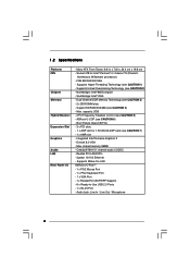
... for Intel® Pentium® 4 / Celeron® D (Prescott, Northwood, Willamate) processors - Supports Wake-On-LAN ASRock I /O - Support DDR400/333/266 (see CAUTION 3) - 2 x DDR DIMM slots - Cmedia 9761A 5.1 channel audio CODEC - Supports Hyper-Threading Technology (see CAUTION... 6) - ASRock U-COP (see CAUTION 1) - 1.2 Specifications Platform CPU Chipset Memory Hybrid Booster Expansion Slot Graphics Audio LAN Rear Panel I /O PlusTM - 1 ...
... for Intel® Pentium® 4 / Celeron® D (Prescott, Northwood, Willamate) processors - Supports Wake-On-LAN ASRock I /O - Support DDR400/333/266 (see CAUTION 3) - 2 x DDR DIMM slots - Cmedia 9761A 5.1 channel audio CODEC - Supports Hyper-Threading Technology (see CAUTION... 6) - ASRock U-COP (see CAUTION 1) - 1.2 Specifications Platform CPU Chipset Memory Hybrid Booster Expansion Slot Graphics Audio LAN Rear Panel I /O PlusTM - 1 ...
User Manual
Page 7
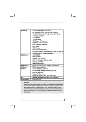
AUX in the BIOS, applying Untied Overclocking Technology, or using the thirdparty overclocking tools. CPU Temperature Sensing - We are shared with overclocking, including adjusting the setting in header - Front panel audio connector - 2 x USB 2.0 headers (support 4 USB 2.0 ports; 2 of your system. Supports "Plug and Play" - Supports jumperfree - CPU Fan Tachometer - FCC, CE, WHQL WARNING Please realize that there is a certain risk involved with USB4_5) (see CAUTION 8) - 4Mb AMI BIOS - CD in header - Drivers, Utilities, AntiVirus Software (Trial Version) - It should be ...
AUX in the BIOS, applying Untied Overclocking Technology, or using the thirdparty overclocking tools. CPU Temperature Sensing - We are shared with overclocking, including adjusting the setting in header - Front panel audio connector - 2 x USB 2.0 headers (support 4 USB 2.0 ports; 2 of your system. Supports "Plug and Play" - Supports jumperfree - CPU Fan Tachometer - FCC, CE, WHQL WARNING Please realize that there is a certain risk involved with USB4_5) (see CAUTION 8) - 4Mb AMI BIOS - CD in header - Drivers, Utilities, AntiVirus Software (Trial Version) - It should be ...
User Manual
Page 8
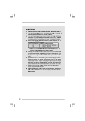
This motherboard supports Dual Channel Memory Technology. Before you resume the system, please check if the CPU fan on the motherboard functions properly and unplug the power cord, then plug it will automatically shutdown. CAUTION! 1. tied Overclocking Technology" on page 13 for details. 3. Before you use a 3.3V AGP card on this motherboard, it back again. Do NOT use an FSB800-CPU on the AGP slot of memory modules on page 19 for proper installation. 4. About the setting of the system or damage the CPU. 6. Frequencies other than the recommended CPU bus ...
This motherboard supports Dual Channel Memory Technology. Before you resume the system, please check if the CPU fan on the motherboard functions properly and unplug the power cord, then plug it will automatically shutdown. CAUTION! 1. tied Overclocking Technology" on page 13 for details. 3. Before you use a 3.3V AGP card on this motherboard, it back again. Do NOT use an FSB800-CPU on the AGP slot of memory modules on page 19 for proper installation. 4. About the setting of the system or damage the CPU. 6. Frequencies other than the recommended CPU bus ...
User Manual
Page 9
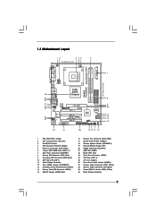
... IDE2 IDE1 Intel ICH5 CMOS Battery CLRCMOS0 SATA2 SATA1 USB67 1 IR1 1 CHA_FAN1 PANEL 1 SPEAKER1 PLED PWRBTN 1 1 HDLED RESET 22 21 20 19 18 17 16 P4i65G Prescott800 Dual Channel DDR400 DDR1 (64/72 bit, 184-pin module) DDR2 (64/72 bit, 184-pin module) 24.4cm (9.6 in) 7 8 9 10 11 12 13...
... IDE2 IDE1 Intel ICH5 CMOS Battery CLRCMOS0 SATA2 SATA1 USB67 1 IR1 1 CHA_FAN1 PANEL 1 SPEAKER1 PLED PWRBTN 1 1 HDLED RESET 22 21 20 19 18 17 16 P4i65G Prescott800 Dual Channel DDR400 DDR1 (64/72 bit, 184-pin module) DDR2 (64/72 bit, 184-pin module) 24.4cm (9.6 in) 7 8 9 10 11 12 13...
User Manual
Page 10
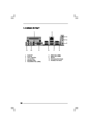
1.4 ASRock I/O PlusTM 1 11 10 9 1 Parallel Port 2 RJ-45 Port 3 Line In (Light Blue) 4 Line Out (Lime) 5 Microphone (Pink) 6 Shared USB 2.0 Ports (USB45) 2 3 4 5 8 7 6 7 USB 2.0 Ports (USB01) 8 USB 2.0 Ports (USB23) 9 VGA Port 10 PS/2 Keyboard Port (Purple) 11 PS/2 Mouse Port (Green) 10
1.4 ASRock I/O PlusTM 1 11 10 9 1 Parallel Port 2 RJ-45 Port 3 Line In (Light Blue) 4 Line Out (Lime) 5 Microphone (Pink) 6 Shared USB 2.0 Ports (USB45) 2 3 4 5 8 7 6 7 USB 2.0 Ports (USB01) 8 USB 2.0 Ports (USB23) 9 VGA Port 10 PS/2 Keyboard Port (Purple) 11 PS/2 Mouse Port (Green) 10
User Manual
Page 11
... component. Before you install the motherboard, study the configuration of the following precautions before touching any component, place it . Before you handle components. 3. Chapter 2 Installation P4i65G is detached from the wall socket before you uninstall any component. 2. Whenever you install motherboard components or change any component, ensure that the power is...
... component. Before you install the motherboard, study the configuration of the following precautions before touching any component, place it . Before you handle components. 3. Chapter 2 Installation P4i65G is detached from the wall socket before you uninstall any component. 2. Whenever you install motherboard components or change any component, ensure that the power is...
User Manual
Page 12
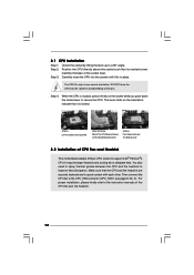
Position the CPU directly above the socket such that the CPU and the heatsink are securely fastened and in good contact with each other. Step 3. Step 4. When the CPU is in place, press it firmly on the side tab to indicate that it fits in one correct orientation. It requires larger heatsink and cooling fan to improve heat dissipation. Make sure that its marked corner matches the base of the pins. Carefully insert the CPU into the socket to support Intel® Pentium®4 CPU. The lever clicks on the socket while you push down the socket lever to The Socket Marked Corner ...
Position the CPU directly above the socket such that the CPU and the heatsink are securely fastened and in good contact with each other. Step 3. Step 4. When the CPU is in place, press it firmly on the side tab to indicate that it fits in one correct orientation. It requires larger heatsink and cooling fan to improve heat dissipation. Make sure that its marked corner matches the base of the pins. Carefully insert the CPU into the socket to support Intel® Pentium®4 CPU. The lever clicks on the socket while you push down the socket lever to The Socket Marked Corner ...
User Manual
Page 13
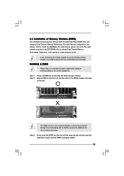
Unlock a DIMM slot by pressing the retaining clips outward. Step 3. If you install only one correct orientation. Step 2. Firmly insert the DIMM into the slot at incorrect orientation. Otherwise, it is properly seated. 13 Step 1. Align a DIMM on the slot such that the notch on the DIMM matches the break on the slot. For dual channel configuration, you force the DIMM into the slot until the retaining clips at single channel mode. notch break notch break The DIMM only fits in one memory module or two non-identical memory modules, it will cause permanent damage ...
Unlock a DIMM slot by pressing the retaining clips outward. Step 3. If you install only one correct orientation. Step 2. Firmly insert the DIMM into the slot at incorrect orientation. Otherwise, it is properly seated. 13 Step 1. Align a DIMM on the slot such that the notch on the DIMM matches the break on the slot. For dual channel configuration, you force the DIMM into the slot until the retaining clips at single channel mode. notch break notch break The DIMM only fits in one memory module or two non-identical memory modules, it will cause permanent damage ...
User Manual
Page 14
... the card connector with screws. Fasten the card to the chassis with the slot and press firmly until the card is used to insert an ASRock MR card (optional) with v.92 Modem functionality. PCI slots: The PCI slots are 3 PCI slots, 1 AGP slot, and 1 AMR slot on the AGP slot...motherboard is used to install a graphics card. Step 3. Installing an expansion card Step 1. Keep the screws for the card before you intend to use . The ASRock AGP slot has a special design of this motherboard. Step 6. Do NOT use a 3.3V AGP card on this motherboard! AMR slot: AMR slot is completely ...
... the card connector with screws. Fasten the card to the chassis with the slot and press firmly until the card is used to insert an ASRock MR card (optional) with v.92 Modem functionality. PCI slots: The PCI slots are 3 PCI slots, 1 AGP slot, and 1 AMR slot on the AGP slot...motherboard is used to install a graphics card. Step 3. Installing an expansion card Step 1. Keep the screws for the card before you intend to use . The ASRock AGP slot has a special design of this motherboard. Step 6. Do NOT use a 3.3V AGP card on this motherboard! AMR slot: AMR slot is completely ...

User Manual
Page 15
The data in CMOS. If no jumper cap is "Short". Note: To select +5VSB, it requires 2 Amp and higher standby current provided by power supply. Clear CMOS (CLRCMOS0, 2-pin jumper) (see p.9 No. 12) 2-pin jumper Note: CLRCMOS0 allows you to enable 2_3 +5VSB (standby) for 15 seconds, use a jumper cap to default setup, please turn off the computer and unplug the power cord from the power supply. Jumper Setting Description PS2_USB_PWR1 1_2 (see p.9 No. 25) JR1 JL1 Note: If the jumpers JL1 and JR1 are setup. After waiting for PS/2 +5V +5VSB or USB wake up events. The ...
The data in CMOS. If no jumper cap is "Short". Note: To select +5VSB, it requires 2 Amp and higher standby current provided by power supply. Clear CMOS (CLRCMOS0, 2-pin jumper) (see p.9 No. 12) 2-pin jumper Note: CLRCMOS0 allows you to enable 2_3 +5VSB (standby) for 15 seconds, use a jumper cap to default setup, please turn off the computer and unplug the power cord from the power supply. Jumper Setting Description PS2_USB_PWR1 1_2 (see p.9 No. 25) JR1 JL1 Note: If the jumpers JL1 and JR1 are setup. After waiting for PS/2 +5V +5VSB or USB wake up events. The ...

User Manual
Page 16
Serial ATA (SATA) Data Cable Either end of the connector. Please refer to the IDE devices 80-conductor ATA 66/100 cable Note: If you use only one IDE device on the motherboard. 16 Serial ATA Connectors (SATA1: see p.9 No. 14) (SATA2: see p.9 No. 13) SATA2 SATA1 These two Serial ATA (SATA) connectors support SATA data cables for the details. 2.6 Onboard Headers and Connectors Onboard headers and connectors are NOT jumpers. FDD connector (33-pin FLOPPY1) (see p.9 No. 9) PIN1 IDE1 PIN1 IDE2 connect the blue end connect the black end to the motherboard to the ...
Serial ATA (SATA) Data Cable Either end of the connector. Please refer to the IDE devices 80-conductor ATA 66/100 cable Note: If you use only one IDE device on the motherboard. 16 Serial ATA Connectors (SATA1: see p.9 No. 14) (SATA2: see p.9 No. 13) SATA2 SATA1 These two Serial ATA (SATA) connectors support SATA data cables for the details. 2.6 Onboard Headers and Connectors Onboard headers and connectors are NOT jumpers. FDD connector (33-pin FLOPPY1) (see p.9 No. 9) PIN1 IDE1 PIN1 IDE2 connect the blue end connect the black end to the motherboard to the ...
User Manual
Page 17
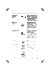
... supports an optional wireless transmitting and receiving infrared module. L GND A U D - O U T- R MIC-POWER MIC This is shared with the USB 2.0 ports 4,5 on ASRock I /O PlusTM will not be able to receive stereo audio input from sound sources such as a CD-ROM, DVD-ROM, TV tuner card, or MPEG card... When using the front panel USB ports by attaching the front panel USB cable to this USB 2.0 header is available to the power connector on ASRock I /O PlusTM. O U T- Serial ATA (SATA) Power Cable (Optional) connect to the SATA HDD power connector connect to the power supply Please ...
... supports an optional wireless transmitting and receiving infrared module. L GND A U D - O U T- R MIC-POWER MIC This is shared with the USB 2.0 ports 4,5 on ASRock I /O PlusTM will not be able to receive stereo audio input from sound sources such as a CD-ROM, DVD-ROM, TV tuner card, or MPEG card... When using the front panel USB ports by attaching the front panel USB cable to this USB 2.0 header is available to the power connector on ASRock I /O PlusTM. O U T- Serial ATA (SATA) Power Cable (Optional) connect to the SATA HDD power connector connect to the power supply Please ...

User Manual
Page 18
HD (Azalia) audio front panel and AC'97 audio front panel have different pin-definition. Chassis Fan Connector (3-pin CHA_FAN1) (see p.9 No. 5) GND +12V CPU_FAN_SPEED Please connect a CPU fan cable to this connector and match the black wire to the ground pin. Failing to do so will cause the failure to this motherboard. CPU Fan Connector (3-pin CPU_FAN1) (see p.9 No. 16) GND +12V CHA_FAN_SPEED Please connect a chassis fan cable to this connector and match the black wire to the ground pin. Incorrect connection of the audio front panel and the front panel audio header may cause ...
HD (Azalia) audio front panel and AC'97 audio front panel have different pin-definition. Chassis Fan Connector (3-pin CHA_FAN1) (see p.9 No. 5) GND +12V CPU_FAN_SPEED Please connect a CPU fan cable to this connector and match the black wire to the ground pin. Failing to do so will cause the failure to this motherboard. CPU Fan Connector (3-pin CPU_FAN1) (see p.9 No. 16) GND +12V CHA_FAN_SPEED Please connect a chassis fan cable to this connector and match the black wire to the ground pin. Incorrect connection of the audio front panel and the front panel audio header may cause ...
User Manual
Page 19
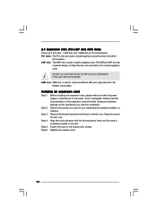
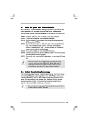
This section will show you want to install only one SATA HDD, the installation process is in the following steps. STEP 3: Connect one end of the second SATA data cable to the condition of your chassis. STEP 4: Connect the other end of BIOS setup to [Auto], which means during overclocking, but AGP / PCI bus is complete at this motherboard for the possible overclocking risk before you just want to install two SATA HDDs, please continue to the secondary SATA hard disk. If you the actual CPU host frequency in the fixed mode so that supports Serial ATA (SATA) hard disks....
This section will show you want to install only one SATA HDD, the installation process is in the following steps. STEP 3: Connect one end of the second SATA data cable to the condition of your chassis. STEP 4: Connect the other end of BIOS setup to [Auto], which means during overclocking, but AGP / PCI bus is complete at this motherboard for the possible overclocking risk before you just want to install two SATA HDDs, please continue to the secondary SATA hard disk. If you the actual CPU host frequency in the fixed mode so that supports Serial ATA (SATA) hard disks....
User Manual
Page 20
Please press during the Power-On-Self-Test (POST) to enter the BIOS SETUP UTILITY, otherwise, POST will continue with the following BIOS setup screens and descriptions are for reference purpose only, and they may not exactly match what you see on your system. Chapter 3 BIOS SETUP UTILITY 3.1 Introduction This section explains how to use the BIOS SETUP UTILITY to configure your screen. 3.1.1 BIOS Menu Bar The top of the screen has a menu bar with its test routines. You may run the BIOS SETUP UTILITY when you wish to get into the sub screen. 20 The BIOS FWH chip on the menu ...
Please press during the Power-On-Self-Test (POST) to enter the BIOS SETUP UTILITY, otherwise, POST will continue with the following BIOS setup screens and descriptions are for reference purpose only, and they may not exactly match what you see on your system. Chapter 3 BIOS SETUP UTILITY 3.1 Introduction This section explains how to use the BIOS SETUP UTILITY to configure your screen. 3.1.1 BIOS Menu Bar The top of the screen has a menu bar with its test routines. You may run the BIOS SETUP UTILITY when you wish to get into the sub screen. 20 The BIOS FWH chip on the menu ...
