User Manual
Page 3
Contents 1 Introduction 5 1.1 Package Contents 5 1.2 Specifications 6 1.3 Motherboard Layout 9 1.4 ASRock I/O PlusTM 10 2 Installation 11 Pre-installation Precautions 11 2.1 CPU Installation 12 2.2 Installation of CPU Fan and Heatsink 12 2.3 Installation of Memory Modules (DIMM 13 2.4 Expansion Slots (PCI, AGP, and AMR Slots 14 2.5 Jumpers Setup 15 2.6 Onboard Headers and Connectors 16 2.7 Serial ATA (...
Contents 1 Introduction 5 1.1 Package Contents 5 1.2 Specifications 6 1.3 Motherboard Layout 9 1.4 ASRock I/O PlusTM 10 2 Installation 11 Pre-installation Precautions 11 2.1 CPU Installation 12 2.2 Installation of CPU Fan and Heatsink 12 2.3 Installation of Memory Modules (DIMM 13 2.4 Expansion Slots (PCI, AGP, and AMR Slots 14 2.5 Jumpers Setup 15 2.6 Onboard Headers and Connectors 16 2.7 Serial ATA (...
User Manual
Page 8
... Management for proper installation. 4. This motherboard supports Untied Overclocking Technology. While CPU overheat is not recommended to spray thermal grease between the CPU and the heatsink when you use a 3.3V AGP card on the AGP slot of memory modules on page 19 for the memory support frequency and its corresponding CPU...
... Management for proper installation. 4. This motherboard supports Untied Overclocking Technology. While CPU overheat is not recommended to spray thermal grease between the CPU and the heatsink when you use a 3.3V AGP card on the AGP slot of memory modules on page 19 for the memory support frequency and its corresponding CPU...
User Manual
Page 9
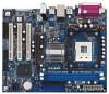
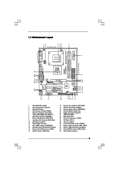
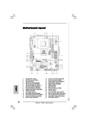
... Intel ICH5 CMOS Battery CLRCMOS0 SATA2 SATA1 USB67 1 IR1 1 CHA_FAN1 PANEL 1 SPEAKER1 PLED PWRBTN 1 1 HDLED RESET 22 21 20 19 18 17 16 P4i65G Prescott800 Dual Channel DDR400 DDR1 (64/72 bit, 184-pin module) DDR2 (64/72 bit, 184-pin module) 24.4cm (9.6 in) 7 8 9... 10 11 12 13 14 15 1 PS2_USB_PWR1 Jumper 2 ATX 12V Connector (ATX12V1) 3 P4-478 CPU Socket 4 CPU Heatsink Retention Module 5 CPU Fan Connector (CPU_FAN1) 6 184-pin DDR DIMM Slots (DDR1- 2) 7 ATX Power Connector (ATXPWR1) 8 Primary IDE Connector (IDE1, Blue) 9 Secondary ...
... Intel ICH5 CMOS Battery CLRCMOS0 SATA2 SATA1 USB67 1 IR1 1 CHA_FAN1 PANEL 1 SPEAKER1 PLED PWRBTN 1 1 HDLED RESET 22 21 20 19 18 17 16 P4i65G Prescott800 Dual Channel DDR400 DDR1 (64/72 bit, 184-pin module) DDR2 (64/72 bit, 184-pin module) 24.4cm (9.6 in) 7 8 9... 10 11 12 13 14 15 1 PS2_USB_PWR1 Jumper 2 ATX 12V Connector (ATX12V1) 3 P4-478 CPU Socket 4 CPU Heatsink Retention Module 5 CPU Fan Connector (CPU_FAN1) 6 184-pin DDR DIMM Slots (DDR1- 2) 7 ATX Power Connector (ATXPWR1) 8 Primary IDE Connector (IDE1, Blue) 9 Secondary ...
User Manual
Page 12
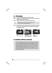
... force the CPU into the socket until it is in one correct orientation. You also need to spray thermal grease between the CPU and the heatsink to the CPU_FAN connector (CPU_FAN1, see page 9, No. 5). For proper installation, please kindly refer to The Socket Marked Corner STEP 4: Push Down And Lock The... it fits in good contact with each other. 2.1 CPU Installation Step 1. Carefully insert the CPU into the socket to avoid bending of CPU Fan and Heatsink This motherboard adopts 478-pin CPU socket to indicate that its marked corner matches the base of the CPU fan and the...
... force the CPU into the socket until it is in one correct orientation. You also need to spray thermal grease between the CPU and the heatsink to the CPU_FAN connector (CPU_FAN1, see page 9, No. 5). For proper installation, please kindly refer to The Socket Marked Corner STEP 4: Push Down And Lock The... it fits in good contact with each other. 2.1 CPU Installation Step 1. Carefully insert the CPU into the socket to avoid bending of CPU Fan and Heatsink This motherboard adopts 478-pin CPU socket to indicate that its marked corner matches the base of the CPU fan and the...
Quick Installation Guide
Page 2
Motherboard Layout English 1 PS2_USB_PWR1 Jumper 2 ATX 12V Connector (ATX12V1) 3 P4-478 CPU Socket 4 CPU Heatsink Retention Module 5 CPU Fan Connector (CPU_FAN1) 6 184-pin DDR DIMM Slots (DDR1- 2) 7 ATX Power Connector (ATXPWR1) 8 Primary IDE Connector (IDE1, Blue) 9 Secondary IDE Connector (IDE2, ... Audio Header (AUDIO1) 27 Internal Audio Connector: AUX1 (White) 28 Internal Audio Connector: CD1 (Black) 29 Shared USB 2.0 Header (USB4_5, Blue) 30 North Bridge Controller 2 ASRock P4i65G Motherboard
Motherboard Layout English 1 PS2_USB_PWR1 Jumper 2 ATX 12V Connector (ATX12V1) 3 P4-478 CPU Socket 4 CPU Heatsink Retention Module 5 CPU Fan Connector (CPU_FAN1) 6 184-pin DDR DIMM Slots (DDR1- 2) 7 ATX Power Connector (ATXPWR1) 8 Primary IDE Connector (IDE1, Blue) 9 Secondary IDE Connector (IDE2, ... Audio Header (AUDIO1) 27 Internal Audio Connector: AUX1 (White) 28 Internal Audio Connector: CD1 (Black) 29 Shared USB 2.0 Header (USB4_5, Blue) 30 North Bridge Controller 2 ASRock P4i65G Motherboard
Quick Installation Guide
Page 7
... CPU and the heatsink when you use a 3.3V AGP card on the motherboard functions properly and unplug the power cord, then plug it back again. Please check the table below for USB 2.0 works fine under Microsoft® Windows® 98/ ME. Before you adopt a DDR333 memory module. 5. CAUTION! 1. English 7 ASRock P4i65G Motherboard CPU...
... CPU and the heatsink when you use a 3.3V AGP card on the motherboard functions properly and unplug the power cord, then plug it back again. Please check the table below for USB 2.0 works fine under Microsoft® Windows® 98/ ME. Before you adopt a DDR333 memory module. 5. CAUTION! 1. English 7 ASRock P4i65G Motherboard CPU...
Quick Installation Guide
Page 8
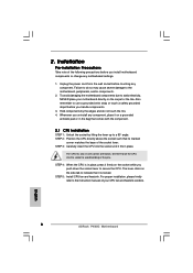
... CPU. DO NOT force the CPU into the socket until it on the carpet or the like. STEP 5: Install CPU fan and heatsink. STEP 2: Position the CPU directly above the socket such that its marked corner matches the base of the following precautions before you handle...o STEP 1: Unlock the socket by the edges and do so may cause severe damage to static electricity, NEVER place your CPU fan and heatsink vendors. 8 ASRock P4i65G Motherboard English To avoid damaging the motherboard components due to the motherboard, peripherals, and/or components. 2. The CPU fits only in place. ...
... CPU. DO NOT force the CPU into the socket until it on the carpet or the like. STEP 5: Install CPU fan and heatsink. STEP 2: Position the CPU directly above the socket such that its marked corner matches the base of the following precautions before you handle...o STEP 1: Unlock the socket by the edges and do so may cause severe damage to static electricity, NEVER place your CPU fan and heatsink vendors. 8 ASRock P4i65G Motherboard English To avoid damaging the motherboard components due to the motherboard, peripherals, and/or components. 2. The CPU fits only in place. ...
