User Manual
Page 3
Contents 1 Introduction 5 1.1 Package Contents 5 1.2 Specifications 6 1.3 Motherboard Layout 9 1.4 ASRock I/O PlusTM 10 2 Installation 11 Pre-installation Precautions 11 2.1 CPU Installation 12 2.2 Installation of CPU Fan and Heatsink 12... Jumpers Setup 15 2.6 Onboard Headers and Connectors 16 2.7 Serial ATA (SATA) Hard Disks Installation 19 2.8 Untied Overclocking Technology 19 3 BIOS SETUP UTILITY 20 3.1 Introduction 20 3.1.1 BIOS Menu Bar 20 3.1.2 Navigation Keys 21 3.2 Main Screen 21 3.3 Advanced Screen 21 3.3.1 CPU Configuration 22 3.3.2 Chipset Configuration 24 3.3.3 ...
Contents 1 Introduction 5 1.1 Package Contents 5 1.2 Specifications 6 1.3 Motherboard Layout 9 1.4 ASRock I/O PlusTM 10 2 Installation 11 Pre-installation Precautions 11 2.1 CPU Installation 12 2.2 Installation of CPU Fan and Heatsink 12... Jumpers Setup 15 2.6 Onboard Headers and Connectors 16 2.7 Serial ATA (SATA) Hard Disks Installation 19 2.8 Untied Overclocking Technology 19 3 BIOS SETUP UTILITY 20 3.1 Introduction 20 3.1.1 BIOS Menu Bar 20 3.1.2 Navigation Keys 21 3.2 Main Screen 21 3.3 Advanced Screen 21 3.3.1 CPU Configuration 22 3.3.2 Chipset Configuration 24 3.3.3 ...
User Manual
Page 5
Chapter 3 and 4 contain the configuration guide to BIOS setup and information of the motherboard and step-bystep guide to the hardware installation. ASRock website http://www.asrock.com 1.1 Package Contents ASRock P4i65G Motherboard (Micro ATX Form Factor: 9.6-in x 7.8-in, 24.4 cm x 19.8 cm) ASRock P4i65G Quick Installation Guide ASRock P4i65G Support CD One 80-conductor Ultra ATA 66/100 IDE...
Chapter 3 and 4 contain the configuration guide to BIOS setup and information of the motherboard and step-bystep guide to the hardware installation. ASRock website http://www.asrock.com 1.1 Package Contents ASRock P4i65G Motherboard (Micro ATX Form Factor: 9.6-in x 7.8-in, 24.4 cm x 19.8 cm) ASRock P4i65G Quick Installation Guide ASRock P4i65G Support CD One 80-conductor Ultra ATA 66/100 IDE...
User Manual
Page 7
...7 Front panel audio connector - 2 x USB 2.0 headers (support 4 USB 2.0 ports; 2 of your system. AMI Legal BIOS - ACPI 1.1 Compliance Wake Up Events - Overclocking may affect your own risk and expense. We are shared with overclocking, including adjusting the setting in ...the BIOS, applying Untied Overclocking Technology, or using the thirdparty overclocking tools. CPU/Chassis FAN connector - 20 pin ATX power connector ...
...7 Front panel audio connector - 2 x USB 2.0 headers (support 4 USB 2.0 ports; 2 of your system. AMI Legal BIOS - ACPI 1.1 Compliance Wake Up Events - Overclocking may affect your own risk and expense. We are shared with overclocking, including adjusting the setting in ...the BIOS, applying Untied Overclocking Technology, or using the thirdparty overclocking tools. CPU/Chassis FAN connector - 20 pin ATX power connector ...
User Manual
Page 9
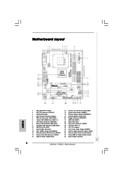
...USB4_5 USB 2.0 1 T: USB4 B: USB5 CD1 Intel 865G Chipset AUDIO1 AUX1 1 JR1 JL1 AUDIO CODEC PCI LAN 1.5V_AGP1 PCI 1 AGP8X Super I/O 1 COM1 4Mb BIOS PCI 2 RoHS FSB800 SATA USB2.0 5.1CH PCI 3 FLOPPY1 AMR1 IDE2 IDE1 Intel ICH5 CMOS Battery CLRCMOS0 SATA2 SATA1 USB67 1 IR1 1 CHA_FAN1 PANEL 1 SPEAKER1 PLED PWRBTN... 1 1 HDLED RESET 22 21 20 19 18 17 16 P4i65G Prescott800 Dual Channel DDR400 DDR1 (64/72 bit, 184-pin module) DDR2 (64/72 bit, 184-pin module) 24.4cm (9.6 in) 7 8 9...
...USB4_5 USB 2.0 1 T: USB4 B: USB5 CD1 Intel 865G Chipset AUDIO1 AUX1 1 JR1 JL1 AUDIO CODEC PCI LAN 1.5V_AGP1 PCI 1 AGP8X Super I/O 1 COM1 4Mb BIOS PCI 2 RoHS FSB800 SATA USB2.0 5.1CH PCI 3 FLOPPY1 AMR1 IDE2 IDE1 Intel ICH5 CMOS Battery CLRCMOS0 SATA2 SATA1 USB67 1 IR1 1 CHA_FAN1 PANEL 1 SPEAKER1 PLED PWRBTN... 1 1 HDLED RESET 22 21 20 19 18 17 16 P4i65G Prescott800 Dual Channel DDR400 DDR1 (64/72 bit, 184-pin module) DDR2 (64/72 bit, 184-pin module) 24.4cm (9.6 in) 7 8 9...
User Manual
Page 19
... the following item. If you apply Untied Overclocking Technology. 19 STEP 7: Connect the other end of the OnBoard IDE Operate Mode option in BIOS setup is complete at this motherboard for the possible overclocking risk before you just want to install two SATA HDDs, please continue to the primary...the SATA data cable to the SATA hard disk. Therefore, CPU FSB is untied during overclocking, FSB enjoys better margin due to the condition of BIOS setup to install the SATA hard disks. You may set "CPU Host Frequency" option of your chassis. STEP 5: Connect the SATA power cable...
... the following item. If you apply Untied Overclocking Technology. 19 STEP 7: Connect the other end of the OnBoard IDE Operate Mode option in BIOS setup is complete at this motherboard for the possible overclocking risk before you just want to install two SATA HDDs, please continue to the primary...the SATA data cable to the SATA hard disk. Therefore, CPU FSB is untied during overclocking, FSB enjoys better margin due to the condition of BIOS setup to install the SATA hard disks. You may set "CPU Host Frequency" option of your chassis. STEP 5: Connect the SATA power cable...
User Manual
Page 20
... is constantly being updated, the following selections: Main To set up the system time/date information Advanced To set up the advanced BIOS features PCIPnP To set up the PCI features Boot To set up the computer. If you start up the chipset features Exit To exit the ...current screen or the BIOS SETUP UTILITY Use < > key or < > key to locate and load the Operating System Security To set up the security features Chipset To set up the...
... is constantly being updated, the following selections: Main To set up the system time/date information Advanced To set up the advanced BIOS features PCIPnP To set up the PCI features Boot To set up the computer. If you start up the chipset features Exit To exit the ...current screen or the BIOS SETUP UTILITY Use < > key or < > key to locate and load the Operating System Security To set up the security features Chipset To set up the...
User Manual
Page 21
... the configurations for the following table for all the settings To save changes and exit the BIOS SETUP UTILITY To jump to the Exit Screen or exit the current screen 3.2 Main Screen When you enter the BIOS SETUP UTILITY, the Main screen will appear and display the system overview Main Advanced... UTILITY H/W Monitor Boot System Overview System Time System Date [14:00:09] [Tue 02/21/2006] BIOS Version : P4i65G BIOS P1.00 Processor Type : Intel (R) Pentium (R) 4 CPU 2.40 GHz Processor Speed : 2400 MHz Microcode Update : F24/1E Cache Size : 512KB Total Memory DIMM 1 DIMM 2 : ...
... the configurations for the following table for all the settings To save changes and exit the BIOS SETUP UTILITY To jump to the Exit Screen or exit the current screen 3.2 Main Screen When you enter the BIOS SETUP UTILITY, the Main screen will appear and display the system overview Main Advanced... UTILITY H/W Monitor Boot System Overview System Time System Date [14:00:09] [Tue 02/21/2006] BIOS Version : P4i65G BIOS P1.00 Processor Type : Intel (R) Pentium (R) 4 CPU 2.40 GHz Processor Speed : 2400 MHz Microcode Update : F24/1E Cache Size : 512KB Total Memory DIMM 1 DIMM 2 : ...
User Manual
Page 22
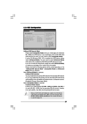
... Spread Spectrum This item should always be [Auto] for better system stability. 22 CPU Host Frequency While entering setup, BIOS auto detects the present CPU host frequency of Boot Failure Guard. The actual CPU host frequency will show in the following item... Monitor Boot Security Exit Advanced Settings WARNING : Setting wrong values in below sections may cause the system to malfunction. 3.3.1 CPU Configuration BIOS SETUP UTILITY Advanced CPU Configuration CPU Host Frequency Actual Frequency (MHz) Boot Failure Guard Spread Spectrum Max CPUID Value Limit CPU Thermal Throttling...
... Spread Spectrum This item should always be [Auto] for better system stability. 22 CPU Host Frequency While entering setup, BIOS auto detects the present CPU host frequency of Boot Failure Guard. The actual CPU host frequency will show in the following item... Monitor Boot Security Exit Advanced Settings WARNING : Setting wrong values in below sections may cause the system to malfunction. 3.3.1 CPU Configuration BIOS SETUP UTILITY Advanced CPU Configuration CPU Host Frequency Actual Frequency (MHz) Boot Failure Guard Spread Spectrum Max CPUID Value Limit CPU Thermal Throttling...
User Manual
Page 24
... of DRAM clocks for memory compatibility when it is set as operating frequency: [133MHz (DDR 266)], [166MHz (DDR 333)], [200MHz (DDR 400)]. Init. 3.3.2 Chipset Configuration BIOS SETUP UTILITY Advanced Chipset Configuration DRAM Frequency [Auto] Flexibility Option [Disabled] Configure DRAM Timing by the contents in the SPD (Serial Presence Detect) device. You...
... of DRAM clocks for memory compatibility when it is set as operating frequency: [133MHz (DDR 266)], [166MHz (DDR 333)], [200MHz (DDR 400)]. Init. 3.3.2 Chipset Configuration BIOS SETUP UTILITY Advanced Chipset Configuration DRAM Frequency [Auto] Flexibility Option [Disabled] Configure DRAM Timing by the contents in the SPD (Serial Presence Detect) device. You...

User Manual
Page 26
... power-soft-off mode. RTC Alarm Power On Use this item to enable or disable PCI devices to turn on the system. 26 3.3.3 ACPI Configuration BIOS SETUP UTILITY Advanced ACPI Configuration Suspend To RAM Restore on AC/Power Loss This allows you to set the power state after an unexpected AC...
... power-soft-off mode. RTC Alarm Power On Use this item to enable or disable PCI devices to turn on the system. 26 3.3.3 ACPI Configuration BIOS SETUP UTILITY Advanced ACPI Configuration Suspend To RAM Restore on AC/Power Loss This allows you to set the power state after an unexpected AC...
User Manual
Page 27
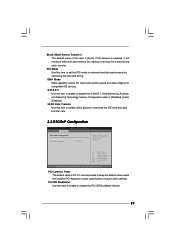
... the "OnBoard IDE Operate Mode" ([Compatible Mode] or [Enhanced Mode]) that you have to select between [Pri IDE + SATA] and [SATA + Sec IDE]. 3.3.4 IDE Configuration BIOS SETUP UTILITY Advanced IDE Configuration OnBoard IDE Operate Mode OnBoard IDE Controller Primary IDE Master Primary IDE Slave Secondary IDE Master Secondary IDE Slave SATA1...
... the "OnBoard IDE Operate Mode" ([Compatible Mode] or [Enhanced Mode]) that you have to select between [Pri IDE + SATA] and [SATA + Sec IDE]. 3.3.4 IDE Configuration BIOS SETUP UTILITY Advanced IDE Configuration OnBoard IDE Operate Mode OnBoard IDE Controller Primary IDE Master Primary IDE Slave Secondary IDE Master Secondary IDE Slave SATA1...

User Manual
Page 28
After selecting the hard disk information into BIOS, use of "Primary IDE Slave", "Secondary IDE Master", "Secondary IDE Slave", "SATA1" and "SATA2" as MO. for IDE ARMD (ATAPI Removable Media Device), such as ...]: This is necessary so that you can be applied to the configurations of IDE device. [Auto]: Select [Auto] to automatically detect the hard disk drive. BIOS SETUP UTILITY Advanced Primary IDE Master Device Vendor Size LBA Mode Block Mode PIO Mode Async DMA Ultra DMA S.M.A.R.T. This is used for Netware and...
After selecting the hard disk information into BIOS, use of "Primary IDE Slave", "Secondary IDE Master", "Secondary IDE Slave", "SATA1" and "SATA2" as MO. for IDE ARMD (ATAPI Removable Media Device), such as ...]: This is necessary so that you can be applied to the configurations of IDE device. [Auto]: Select [Auto] to automatically detect the hard disk drive. BIOS SETUP UTILITY Advanced Primary IDE Master Device Vendor Size LBA Mode Block Mode PIO Mode Async DMA Ultra DMA S.M.A.R.T. This is used for Netware and...
User Manual
Page 29
...], [Auto], [Enabled]. 32-Bit Data Transfer Use this item to enable 32-bit access to maximize the IDE hard disk data transfer rate. 3.3.5 PCIPnP Configuration BIOS SETUP UTILITY Advanced PCI / PnP Configuration PCI Latency Timer PCI IDE BusMaster [32] [Enabled] Value in units of this item to set the PIO mode...
...], [Auto], [Enabled]. 32-Bit Data Transfer Use this item to enable 32-bit access to maximize the IDE hard disk data transfer rate. 3.3.5 PCIPnP Configuration BIOS SETUP UTILITY Advanced PCI / PnP Configuration PCI Latency Timer PCI IDE BusMaster [32] [Enabled] Value in units of this item to set the PIO mode...
User Manual
Page 30
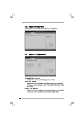
...Select Screen Select Item Change Option General Help Load Defaults Save and Exit Exit v02.54 (C) Copyright 1985-2003, American Megatrends, Inc. 3.3.7 Super IO Configuration BIOS SETUP UTILITY Advanced Configure Super IO Chipset OnBoard Floppy Controller Serial Port Address Infrared Port Address Parallel Port Address Parallel Port Mode EPP Version ECP... Mode DMA Channel Parallel Port IRQ [Enabled] [3F8 / IRQ4] [Disabled] [378] [ECP + EPP] [1.9] [DMA3] [IRQ7] Allow BIOS to set the address for the onboard infrared port or disable it .
...Select Screen Select Item Change Option General Help Load Defaults Save and Exit Exit v02.54 (C) Copyright 1985-2003, American Megatrends, Inc. 3.3.7 Super IO Configuration BIOS SETUP UTILITY Advanced Configure Super IO Chipset OnBoard Floppy Controller Serial Port Address Infrared Port Address Parallel Port Address Parallel Port Mode EPP Version ECP... Mode DMA Channel Parallel Port IRQ [Enabled] [3F8 / IRQ4] [Disabled] [378] [ECP + EPP] [1.9] [DMA3] [IRQ7] Allow BIOS to set the address for the onboard infrared port or disable it .
User Manual
Page 31
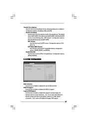
... Version Use this item to enable or disable the support to emulate legacy I/O devices such as mouse, keyboard,... Configuration options: [IRQ5] and [IRQ7]. 3.3.8 USB Configuration BIOS SETUP UTILITY Advanced USB Configuration USB Controller USB 2.0 Support Legacy USB Support [Enabled] [Enabled] [Disabled] To enable or disable the onboard USB controllers. +F1 F9...
... Version Use this item to enable or disable the support to emulate legacy I/O devices such as mouse, keyboard,... Configuration options: [IRQ5] and [IRQ7]. 3.3.8 USB Configuration BIOS SETUP UTILITY Advanced USB Configuration USB Controller USB 2.0 Support Legacy USB Support [Enabled] [Enabled] [Disabled] To enable or disable the onboard USB controllers. +F1 F9...

User Manual
Page 32
BIOS SETUP UTILITY Main Advanced H/W Monitor Boot Security Exit Hardware Health Event Monitoring CPU Temperature M / B Temperature CPU Fan Speed Chassis Fan Speed Vcore + 3.30V + 5.00V + 12....
BIOS SETUP UTILITY Main Advanced H/W Monitor Boot Security Exit Hardware Health Event Monitoring CPU Temperature M / B Temperature CPU Fan Speed Chassis Fan Speed Vcore + 3.30V + 5.00V + 12....

User Manual
Page 33
Main Advanced BIOS SETUP UTILITY H/W Monitor Boot Security Exit Boot Settings Boot Settings Configuration Boot Device Priority Hard Disk Drives Removable Drives CD / DVD Drives Configure Settings during ... Sub Screen F1 General Help F9 Load Defaults F10 Save and Exit ESC Exit v02.54 (C) Copyright 1985-2003, American Megatrends, Inc. 3.5.1 Boot Settings Configuration BIOS SETUP UTILITY Boot Boot Settings Configuration Boot From Network Bootup Num-Lock [Disabled] [On] To enable or disable the boot from network feature. +F1 F9...
Main Advanced BIOS SETUP UTILITY H/W Monitor Boot Security Exit Boot Settings Boot Settings Configuration Boot Device Priority Hard Disk Drives Removable Drives CD / DVD Drives Configure Settings during ... Sub Screen F1 General Help F9 Load Defaults F10 Save and Exit ESC Exit v02.54 (C) Copyright 1985-2003, American Megatrends, Inc. 3.5.1 Boot Settings Configuration BIOS SETUP UTILITY Boot Boot Settings Configuration Boot From Network Bootup Num-Lock [Disabled] [On] To enable or disable the boot from network feature. +F1 F9...
User Manual
Page 34
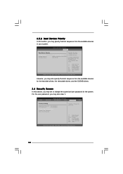
...For the user password, you may also clear it. A device enclosed in parenthesis has been disabled in your system. BIOS SETUP UTILITY Main Advanced H/W Monitor Boot Security Exit Security Settings Supervisor Password : Not Installed User Password : Not Installed ...Change Supervisor Password Change User Password Clear User Password Install or Change the password. BIOS SETUP UTILITY Boot Boot Device Priority 1st Boot Device 2nd Boot Device 3rd Boot Device [1st FLOPPY DRIVE] [HDD: PM-MAXTOR 6L08] ...
...For the user password, you may also clear it. A device enclosed in parenthesis has been disabled in your system. BIOS SETUP UTILITY Main Advanced H/W Monitor Boot Security Exit Security Settings Supervisor Password : Not Installed User Password : Not Installed ...Change Supervisor Password Change User Password Clear User Password Install or Change the password. BIOS SETUP UTILITY Boot Boot Device Priority 1st Boot Device 2nd Boot Device 3rd Boot Device [1st FLOPPY DRIVE] [HDD: PM-MAXTOR 6L08] ...

User Manual
Page 35
...When you select this option, it will pop-out the following message, "Discard changes and exit setup?" Select [OK] to exit the BIOS SETUP UTILITY without saving any changes. Discard Changes and Exit When you select this option, it will pop-out the following message, "...Save configuration changes and exit setup?" 3.7 Exit Screen Main BIOS SETUP UTILITY Advanced H/W Monitro Boot Security Exit Exit Options Save Changes and Exit Discard Changes and Exit Discard Changes Load Optimal Defaults Exit ...
...When you select this option, it will pop-out the following message, "Discard changes and exit setup?" Select [OK] to exit the BIOS SETUP UTILITY without saving any changes. Discard Changes and Exit When you select this option, it will pop-out the following message, "...Save configuration changes and exit setup?" 3.7 Exit Screen Main BIOS SETUP UTILITY Advanced H/W Monitro Boot Security Exit Exit Options Save Changes and Exit Discard Changes and Exit Discard Changes Load Optimal Defaults Exit ...
Quick Installation Guide
Page 2
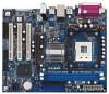
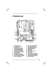
... (FLOPPY1) 21 AMR Slot (AMR1) 22 BIOS FWH Chip 23 Serial Port Connector (COM1) 24 PCI Slots (PCI1- 3) 25 JR1 / JL1 Jumpers 26 Front Panel Audio Header (AUDIO1) 27 Internal Audio Connector: AUX1 (White) 28 Internal Audio Connector: CD1 (Black) 29 Shared USB 2.0 Header (USB4_5, Blue) 30 North Bridge Controller 2 ASRock P4i65G Motherboard
... (FLOPPY1) 21 AMR Slot (AMR1) 22 BIOS FWH Chip 23 Serial Port Connector (COM1) 24 PCI Slots (PCI1- 3) 25 JR1 / JL1 Jumpers 26 Front Panel Audio Header (AUDIO1) 27 Internal Audio Connector: AUX1 (White) 28 Internal Audio Connector: CD1 (Black) 29 Shared USB 2.0 Header (USB4_5, Blue) 30 North Bridge Controller 2 ASRock P4i65G Motherboard


