User Manual
Page 1
All rights reserved. 1 880G Extreme3 User Manual Version 1.0 Published March 2010 Copyright©2010 ASRock INC.
All rights reserved. 1 880G Extreme3 User Manual Version 1.0 Published March 2010 Copyright©2010 ASRock INC.
User Manual
Page 2
... copyrights of their respective companies, and are furnished for backup purpose, without notice, and should not be constructed as a commitment by ASRock. With respect to the contents of this manual, ASRock does not provide warranty of any kind, either expressed or implied, including but not limited to infringe. This device complies with Part...
... copyrights of their respective companies, and are furnished for backup purpose, without notice, and should not be constructed as a commitment by ASRock. With respect to the contents of this manual, ASRock does not provide warranty of any kind, either expressed or implied, including but not limited to infringe. This device complies with Part...
User Manual
Page 5
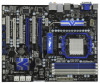
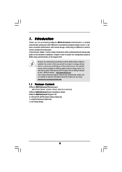
...-step guide to change without further notice. www.asrock.com/support/index.asp 1.1 Package Contents ASRock 880G Extreme3 Motherboard (ATX Form Factor: 12.0-in x 9.6-in, 30.5 cm x 24.4 cm) ASRock 880G Extreme3 Quick Installation Guide ASRock 880G Extreme3 Support CD 4 x Serial ATA (SATA) Data Cables (Optional) 1 x eSATA3 Bracket (Optional) 1 x I/O Panel Shield 5 In this manual, chapter 1 and 2 contain introduction of this motherboard...
...-step guide to change without further notice. www.asrock.com/support/index.asp 1.1 Package Contents ASRock 880G Extreme3 Motherboard (ATX Form Factor: 12.0-in x 9.6-in, 30.5 cm x 24.4 cm) ASRock 880G Extreme3 Quick Installation Guide ASRock 880G Extreme3 Support CD 4 x Serial ATA (SATA) Data Cables (Optional) 1 x eSATA3 Bracket (Optional) 1 x I/O Panel Shield 5 In this manual, chapter 1 and 2 contain introduction of this motherboard...
User Manual
Page 15
... firmly on the side tab to indicate that it fits in one correct orientation. Unlock the socket by lifting the lever up to the instruction manuals of CPU Fan and Heatsink After you push down the socket lever to dissipate heat.
... firmly on the side tab to indicate that it fits in one correct orientation. Unlock the socket by lifting the lever up to the instruction manuals of CPU Fan and Heatsink After you push down the socket lever to dissipate heat.
User Manual
Page 22
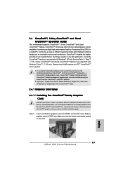
... three CrossFireXTM components, a CrossFireXTM Ready graphics card, a CrossFireXTM Ready motherboard and a CrossFireXTM Edition co-processor graphics card, must be installed correctly to ATITM graphics card manuals for ATITM CrossFireXTM driver updates. 1. In below procedures, we use Radeon HD 3870 as 12-pipe cards while in the future, please refer to benefit...
... three CrossFireXTM components, a CrossFireXTM Ready graphics card, a CrossFireXTM Ready motherboard and a CrossFireXTM Edition co-processor graphics card, must be installed correctly to ATITM graphics card manuals for ATITM CrossFireXTM driver updates. 1. In below procedures, we use Radeon HD 3870 as 12-pipe cards while in the future, please refer to benefit...

User Manual
Page 33
... p.11 No. 21) PLED+ PLEDPWRBTN# GND 1 DUMMY RESET# GND HDLEDHDLED+ This header accommodates several system front panel functions. The LED keeps blinking in our manual and chassis manual to indicate system power status. High Definition Audio supports Jack Sensing, but the panel wire on when the system is off in S3/S4...
... p.11 No. 21) PLED+ PLEDPWRBTN# GND 1 DUMMY RESET# GND HDLEDHDLED+ This header accommodates several system front panel functions. The LED keeps blinking in our manual and chassis manual to indicate system power status. High Definition Audio supports Jack Sensing, but the panel wire on when the system is off in S3/S4...
User Manual
Page 38
... and uncompress it. The POST code checkpoints are based on KBC. Initialized CMOS as system timer. Initialize BIOS, POST, Runtime data area. Verify CMOS checksum manually by reading storage area. Check CMOS diagnostic byte to ADM module for initialization. The BAT test is bad, update CMOS with power-on POST entry...
... and uncompress it. The POST code checkpoints are based on KBC. Initialized CMOS as system timer. Initialize BIOS, POST, Runtime data area. Verify CMOS checksum manually by reading storage area. Check CMOS diagnostic byte to ADM module for initialization. The BAT test is bad, update CMOS with power-on POST entry...
User Manual
Page 40
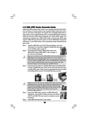
... player, A/V receiver and a compatible digital audio or video monitor, such as HDTV. Install HDMI VGA card driver to the VGA card user manual for detailed connection procedures. For the pin definition of HDMI_SPDIF connectors on this motherboard and the HDMI VGA card. Connect the white end (B or... C) of HDMI_SPDIF cable to the user manual of PCI Express VGA card. For example, this motherboard, please carefully follow the below steps. •Step 1. Connect the HDMI output ...
... player, A/V receiver and a compatible digital audio or video monitor, such as HDTV. Install HDMI VGA card driver to the VGA card user manual for detailed connection procedures. For the pin definition of HDMI_SPDIF connectors on this motherboard and the HDMI VGA card. Connect the white end (B or... C) of HDMI_SPDIF cable to the user manual of PCI Express VGA card. For example, this motherboard, please carefully follow the below steps. •Step 1. Connect the HDMI output ...
User Manual
Page 42
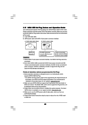
... package. 5. A. 7-pin SATA data cable B. SATA data cable (Red) B. Make sure your SATA3 HDD can support Hot Plug function from your dealer or HDD user manual. The SATA3 HDD, which cannot support Hot Plug function, will cause the HDD damage and data loss. Please read below instructions step by the chipset... sure the SATA3 driver is definitely not able to support Hot Plug and will be processed. 2. Below operation procedure is available on our website: www.asrock.com 2. The latest SATA3 driver is designed only for SATA3 HDD in the product spec on our support website: www...
... package. 5. A. 7-pin SATA data cable B. SATA data cable (Red) B. Make sure your SATA3 HDD can support Hot Plug function from your dealer or HDD user manual. The SATA3 HDD, which cannot support Hot Plug function, will cause the HDD damage and data loss. Please read below instructions step by the chipset... sure the SATA3 driver is definitely not able to support Hot Plug and will be processed. 2. Below operation procedure is available on our website: www.asrock.com 2. The latest SATA3 driver is designed only for SATA3 HDD in the product spec on our support website: www...
User Manual
Page 51
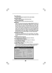
... Configuration Overclock Mode CPU Frequency (MHZ) CPU DOC Frequency (MHZ) PCIE Frequency (MHz) Spread Spectrum Boot Failure Guard Boot Failure Guard Count ASRock UCC CPU Active Core Control [Auto] [200] [Auto] [100] [Auto] [Enabled] [3] [Disabled] [All Cores] Processor Maximum ...Frequency x10.5 2100 MHZ North Bridge Maximum Frequency x9.0 1800 MHZ Processor Maximum Voltage 1.2500 V Multiplier/Voltage Change [Manual] If Manual, multiplier and voltage will be disabled. Boot Failure Guard Count Enable or disable the feature of Boot Failure Guard. The configuration ...
... Configuration Overclock Mode CPU Frequency (MHZ) CPU DOC Frequency (MHZ) PCIE Frequency (MHz) Spread Spectrum Boot Failure Guard Boot Failure Guard Count ASRock UCC CPU Active Core Control [Auto] [200] [Auto] [100] [Auto] [Enabled] [3] [Disabled] [All Cores] Processor Maximum ...Frequency x10.5 2100 MHZ North Bridge Maximum Frequency x9.0 1800 MHZ Processor Maximum Voltage 1.2500 V Multiplier/Voltage Change [Manual] If Manual, multiplier and voltage will be disabled. Boot Failure Guard Count Enable or disable the feature of Boot Failure Guard. The configuration ...
User Manual
Page 68
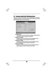
....091V Enable/Disable CPU Quiet Fan Function. CPU Fan Setting This allows you to set the CPU fan speed. Configuration options: [Full On] and [Manual mode]. Chassis Fan 2 Setting This allows you to set the chassis fan 1 speed. The default is value [Full On]. Chassis Fan 1 Setting ..., CPU fan speed, chassis fan speed, and the critical voltage. The default is value [Full On]. 68 Configuration options: [Full On] and [Manual mode]. The default is value [Full On]. The default is value [Full On]. 3.5 Hardware Health Event Monitoring Screen In this section, it allows you...
....091V Enable/Disable CPU Quiet Fan Function. CPU Fan Setting This allows you to set the CPU fan speed. Configuration options: [Full On] and [Manual mode]. Chassis Fan 2 Setting This allows you to set the chassis fan 1 speed. The default is value [Full On]. Chassis Fan 1 Setting ..., CPU fan speed, chassis fan speed, and the critical voltage. The default is value [Full On]. 68 Configuration options: [Full On] and [Manual mode]. The default is value [Full On]. The default is value [Full On]. 3.5 Hardware Health Event Monitoring Screen In this section, it allows you...
Quick Installation Guide
Page 5
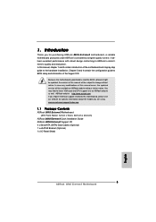
... 1 and 2 contain introduction of the Support CD. In this manual will be subject to this manual occur, the updated version will be updated, the content of this motherboard, please visit our website for purchasing ASRock 880G Extreme3 motherboard, a reliable motherboard produced under ASRock's consistently stringent quality control. It delivers excellent performance with robust design conforming to...
... 1 and 2 contain introduction of the Support CD. In this manual will be subject to this manual occur, the updated version will be updated, the content of this motherboard, please visit our website for purchasing ASRock 880G Extreme3 motherboard, a reliable motherboard produced under ASRock's consistently stringent quality control. It delivers excellent performance with robust design conforming to...
Quick Installation Guide
Page 12
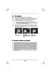
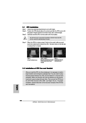
...The Socket Lever 2.2 Installation of CPU Fan and Heatsink After you push down the socket lever to improve heat dissipation. Step 4. English 12 ASRock 880G Extreme3 Motherboard Step 2. The CPU fits only in place. DO NOT force the CPU into the socket until it is necessary to install a larger... each other. The lever clicks on the socket while you install the CPU into this motherboard, it firmly on the side tab to the instruction manuals of the pins. 2.1 CPU Installation Step 1. Carefully insert the CPU into the socket to the CPU FAN connector (CPU_FAN1, see Page 2, No...
...The Socket Lever 2.2 Installation of CPU Fan and Heatsink After you push down the socket lever to improve heat dissipation. Step 4. English 12 ASRock 880G Extreme3 Motherboard Step 2. The CPU fits only in place. DO NOT force the CPU into the socket until it is necessary to install a larger... each other. The lever clicks on the socket while you install the CPU into this motherboard, it firmly on the side tab to the instruction manuals of the pins. 2.1 CPU Installation Step 1. Carefully insert the CPU into the socket to the CPU FAN connector (CPU_FAN1, see Page 2, No...
Quick Installation Guide
Page 19
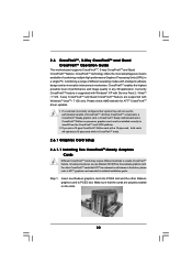
...; XP with Service Pack 2 / VistaTM / 7 OS. 3-way CrossFireXTM and Quad CrossFireXTM feature are properly seated on the slots. 19 ASRock 880G Extreme3 Motherboard English For other Radeon graphics card to ATITM graphics card manuals for ATITM CrossFireXTM driver updates. 1. Please check AMD website for detailed installation guide. Combining a range of CrossFireXTM. All three CrossFireXTM...
...; XP with Service Pack 2 / VistaTM / 7 OS. 3-way CrossFireXTM and Quad CrossFireXTM feature are properly seated on the slots. 19 ASRock 880G Extreme3 Motherboard English For other Radeon graphics card to ATITM graphics card manuals for ATITM CrossFireXTM driver updates. 1. Please check AMD website for detailed installation guide. Combining a range of CrossFireXTM. All three CrossFireXTM...
Quick Installation Guide
Page 30
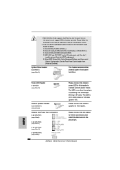
The LED keeps blinking in our manual and chassis manual to install your system. 2. The LED is operating. If you use AC'97 audio panel, please install it to MIC2_L. Connect Mic_IN (MIC) to the ... p.2 No. 20) Please connect the chassis power LED to this header. C. Enter BIOS Setup Utility. Please connect the chassis speaker to the ground pin. 30 ASRock 880G Extreme3 Motherboard English Chassis and Power Fan Connectors (3-pin CHA_FAN1) (see p.2 No. 9) (3-pin CHA_FAN2) (see p.2 No. 11) (3-pin CHA_FAN3) (see p.2 No. 12) (3-pin PWR_FAN1) (see p.2 No...
The LED keeps blinking in our manual and chassis manual to install your system. 2. The LED is operating. If you use AC'97 audio panel, please install it to MIC2_L. Connect Mic_IN (MIC) to the ... p.2 No. 20) Please connect the chassis power LED to this header. C. Enter BIOS Setup Utility. Please connect the chassis speaker to the ground pin. 30 ASRock 880G Extreme3 Motherboard English Chassis and Power Fan Connectors (3-pin CHA_FAN1) (see p.2 No. 9) (3-pin CHA_FAN2) (see p.2 No. 11) (3-pin CHA_FAN3) (see p.2 No. 12) (3-pin PWR_FAN1) (see p.2 No...
Quick Installation Guide
Page 35
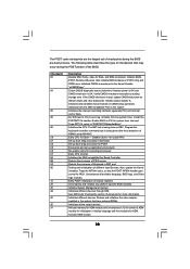
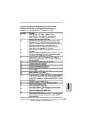
...Detects the presence of document for initialization. Also, update the Kernel Variables. Initializes different devices. Activate ADM module. 35 ASRock 880G Extreme3 Motherboard English Initialize CH-0 as mentioned in KBC port. Traps the INT09h vector, so that may occur during the ... specific BIOS modules. Allocate memory for system timer interrupt. Check CMOS diagnostic byte to "POSTINT1ChHandlerBlock." Verify CMOS checksum manually by reading storage area. Initializes data variables that have optional ROMs. Initializes all available language, BIOS logo, and ...
...Detects the presence of document for initialization. Also, update the Kernel Variables. Initializes different devices. Activate ADM module. 35 ASRock 880G Extreme3 Motherboard English Initialize CH-0 as mentioned in KBC port. Traps the INT09h vector, so that may occur during the ... specific BIOS modules. Allocate memory for system timer interrupt. Check CMOS diagnostic byte to "POSTINT1ChHandlerBlock." Verify CMOS checksum manually by reading storage area. Initializes data variables that have optional ROMs. Initializes all available language, BIOS logo, and ...
Quick Installation Guide
Page 39
... to select among the predetermined choices. The Support CD that will display the Main Menu automatically if "AUTORUN" is designed to display the menus. 39 ASRock 880G Extreme3 Motherboard English The BIOS Setup program is enabled in your CD-ROM drive. It will enhance motherboard features. BIOS Information The Flash Memory on the... your computer. 3. otherwise, POST continues with the motherboard contains necessary drivers and useful utilities that came with its various sub-menus and to the User Manual (PDF file) contained in the Support CD to be user-friendly.
... to select among the predetermined choices. The Support CD that will display the Main Menu automatically if "AUTORUN" is designed to display the menus. 39 ASRock 880G Extreme3 Motherboard English The BIOS Setup program is enabled in your CD-ROM drive. It will enhance motherboard features. BIOS Information The Flash Memory on the... your computer. 3. otherwise, POST continues with the motherboard contains necessary drivers and useful utilities that came with its various sub-menus and to the User Manual (PDF file) contained in the Support CD to be user-friendly.
RAID Installation Guide
Page 2
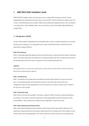
... fault tolerance of the same model and capacity when creating a RAID set the option to RAID mode by following the detailed instruction of the "User Manual" in a RAID 10 solution for "Redundant Array of Independent Disks", which is called data striping that copies and maintains an identical image of a single disk...
... fault tolerance of the same model and capacity when creating a RAID set the option to RAID mode by following the detailed instruction of the "User Manual" in a RAID 10 solution for "Redundant Array of Independent Disks", which is called data striping that copies and maintains an identical image of a single disk...
RAID Installation Guide
Page 8
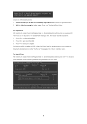
... the full capacity of the disk drives to allocate a portion of the disk drives for one of the following the detailed instruction of the "User Manual" in Disk Assignments as the above -mentioned procedures, press to the first logical drive. Split the disk drives among two logical drives: Please read "One...
... the full capacity of the disk drives to allocate a portion of the disk drives for one of the following the detailed instruction of the "User Manual" in Disk Assignments as the above -mentioned procedures, press to the first logical drive. Split the disk drives among two logical drives: Please read "One...
RAID Installation Guide
Page 9
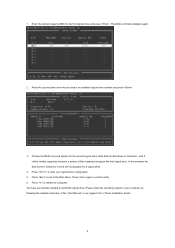
... and options for the first logical drive and press . Note that the disk drives in Channels 1 and 2 reflect smaller capacities because a portion of the "User Manual" in Channels 3 and 4 are not assigned to select an available logical drive number and press . 3. Press to save your computer by following the detailed instruction...
... and options for the first logical drive and press . Note that the disk drives in Channels 1 and 2 reflect smaller capacities because a portion of the "User Manual" in Channels 3 and 4 are not assigned to select an available logical drive number and press . 3. Press to save your computer by following the detailed instruction...
