User Manual
Page 9
... 1800/1600MHz memory speed is supported depends on the AM3 CPU you implement Dual Channel Memory Technology, make sure to read "Untied Overclocking Technology" on our website for the compatible memory modules. We are not responsible for the latest information. 7. ASRock website http://www.asrock.com 5. ASRock UCC (Unlock CPU Core) feature simplifies AMD CPU activation. As long as a simple switch of your own risk and expense. This motherboard supports Untied Overclocking Technology. Please be...
... 1800/1600MHz memory speed is supported depends on the AM3 CPU you implement Dual Channel Memory Technology, make sure to read "Untied Overclocking Technology" on our website for the compatible memory modules. We are not responsible for the latest information. 7. ASRock website http://www.asrock.com 5. ASRock UCC (Unlock CPU Core) feature simplifies AMD CPU activation. As long as a simple switch of your own risk and expense. This motherboard supports Untied Overclocking Technology. Please be...
User Manual
Page 10
... or damage the CPU. 14. With this tool and save your USB flash drive, floppy disk or hard drive, then you resume the system, please check if the CPU fan on the same motherboard. 13. According to Intel's suggestion, the EuP ready power supply must use Intelligent Energy Saver function, please enable Cool 'n' Quiet option in the BIOS setup in off mode condition. With OC DNA, you install the PC...
... or damage the CPU. 14. With this tool and save your USB flash drive, floppy disk or hard drive, then you resume the system, please check if the CPU fan on the same motherboard. 13. According to Intel's suggestion, the EuP ready power supply must use Intelligent Energy Saver function, please enable Cool 'n' Quiet option in the BIOS setup in off mode condition. With OC DNA, you install the PC...
User Manual
Page 11
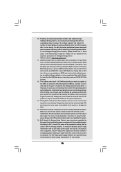
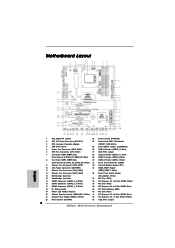
... (LED) 39 SPI Flash Memory (8Mb) 19 Power LED Header (PLED1) 40 PCI Slot (PCI1) 20 Chassis Speaker Header (SPEAKER 1, White) 41 PCI Express 2.0 x16 Slot (PCIE2; White) 22 Reset Switch (RSTBTN) 43 USB_PW2 Jumper 11 Blue) 21 System Panel Header (PANEL1, White) 42 PCI Express 2.0 x1 Slot (PCIE1; White) 31 Serial Port Connector (COM1) 9 Chassis Fan Connector (CHA_FAN1) 32 Infrared Module Header (IR1) 10 ATX Power Connector (ATXPWR1) 33 HDMI_SPDIF Header 11 Chassis Fan Connector (CHA_FAN2) (HDMI_SPDIF1, White) 12 Chassis Fan Connector (CHA_FAN3) 34 Front Panel Audio Header...
... (LED) 39 SPI Flash Memory (8Mb) 19 Power LED Header (PLED1) 40 PCI Slot (PCI1) 20 Chassis Speaker Header (SPEAKER 1, White) 41 PCI Express 2.0 x16 Slot (PCIE2; White) 22 Reset Switch (RSTBTN) 43 USB_PW2 Jumper 11 Blue) 21 System Panel Header (PANEL1, White) 42 PCI Express 2.0 x1 Slot (PCIE1; White) 31 Serial Port Connector (COM1) 9 Chassis Fan Connector (CHA_FAN1) 32 Infrared Module Header (IR1) 10 ATX Power Connector (ATXPWR1) 33 HDMI_SPDIF Header 11 Chassis Fan Connector (CHA_FAN2) (HDMI_SPDIF1, White) 12 Chassis Fan Connector (CHA_FAN3) 34 Front Panel Audio Header...

User Manual
Page 19
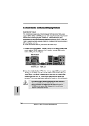
... start to use dual monitor function on the I /O panel, or connect HDMI monitor cable to HDMI port on this motherboard. VGA/D-Sub port VGA/DVI-D port HDMI port 2. This motherboard also provides independent display controllers for DVI-D, D-Sub and HDMI to VGA/D-Sub port on the I /O panel. Connect DVI-D monitor cable to VGA/DVI-D port on the I/O panel, connect D-Sub monitor cable to support dual VGA output so that DVI-D, D-sub and HDMI can freely enjoy the benefits of dual monitor function after your system boots. When one of them is enabled...
... start to use dual monitor function on the I /O panel, or connect HDMI monitor cable to HDMI port on this motherboard. VGA/D-Sub port VGA/DVI-D port HDMI port 2. This motherboard also provides independent display controllers for DVI-D, D-Sub and HDMI to VGA/D-Sub port on the I /O panel. Connect DVI-D monitor cable to VGA/DVI-D port on the I/O panel, connect D-Sub monitor cable to support dual VGA output so that DVI-D, D-sub and HDMI can freely enjoy the benefits of dual monitor function after your system boots. When one of them is enabled...
User Manual
Page 26
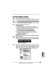
...): http://www.microsoft.com/windowsxp/sp2/default.mspx B. Install the required drivers to uninstall any VGA driver installed in your system, there is an optional download. Please check Microsoft website for ATITM driver updates. For Windows® 7 / VistaTM OS: Install the CATALYST Control Center. Double-click "ATI Catalyst Control Center". Click "View", select "CrossFireXTM", and then check the item "Enable CrossFireXTM". Select "3 GPUs" and click...
...): http://www.microsoft.com/windowsxp/sp2/default.mspx B. Install the required drivers to uninstall any VGA driver installed in your system, there is an optional download. Please check Microsoft website for ATITM driver updates. For Windows® 7 / VistaTM OS: Install the CATALYST Control Center. Double-click "ATI Catalyst Control Center". Click "View", select "CrossFireXTM", and then check the item "Enable CrossFireXTM". Select "3 GPUs" and click...
User Manual
Page 39
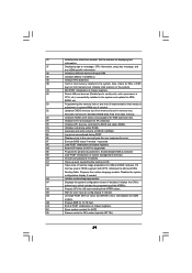
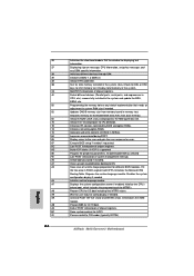
..., CPU information, setup key message, and any kind of implementation that needs an adjustment in system RAM size if needed. 52 Updates CMOS memory size from base memory. 60 Initializes NUM-LOCK status and programs the KBD typematic rate. 75 Initialize Int-13 and prepare for different BIOS modules. A7 Displays the system configuration screen if enabled. A9 Wait for ACPI. 00 Passes control to limit memory test. Enable/Disable...
..., CPU information, setup key message, and any kind of implementation that needs an adjustment in system RAM size if needed. 52 Updates CMOS memory size from base memory. 60 Initializes NUM-LOCK status and programs the KBD typematic rate. 75 Initialize Int-13 and prepare for different BIOS modules. A7 Displays the system configuration screen if enabled. A9 Wait for ACPI. 00 Passes control to limit memory test. Enable/Disable...
User Manual
Page 40
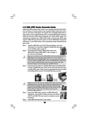
... compatible digital audio/video source, such as a set-top box, DVD player, A/V receiver and a compatible digital audio or video monitor, such as HDTV. Connect the HDMI output connector on HDMI VGA card, please refer to this motherboard. Please refer to HDMI device, such as a digital television (DTV). To use HDMI function on the motherboard. Step 2. For the pin definition of HDMI_SPDIF header and HDMI_SPDIF cable connectors, please refer to the same pin definition. Step 4. 2.12 HDMI_SPDIF Header Connection Guide HDMI (High...
... compatible digital audio/video source, such as a set-top box, DVD player, A/V receiver and a compatible digital audio or video monitor, such as HDTV. Connect the HDMI output connector on HDMI VGA card, please refer to this motherboard. Please refer to HDMI device, such as a digital television (DTV). To use HDMI function on the motherboard. Step 2. For the pin definition of HDMI_SPDIF header and HDMI_SPDIF cable connectors, please refer to the same pin definition. Step 4. 2.12 HDMI_SPDIF Header Connection Guide HDMI (High...
User Manual
Page 42
... sure to use the SATA power cable & data cable, which supports SATA3 HDD Hot Plug. * The SATA3 Hot Plug feature might not be supported by step to power supply 1. Even some SATA3 HDDs provide both SATA 15-pin power connector and IDE 1x4-pin conventional power connector interfaces, the IDE 1x4-pin conventional power connector interface is indicated in RAID / AHCI mode. Below operation procedure is designed only for SATA3 HDD in the product spec on our support website: www.asrock.com...
... sure to use the SATA power cable & data cable, which supports SATA3 HDD Hot Plug. * The SATA3 Hot Plug feature might not be supported by step to power supply 1. Even some SATA3 HDDs provide both SATA 15-pin power connector and IDE 1x4-pin conventional power connector interfaces, the IDE 1x4-pin conventional power connector interface is indicated in RAID / AHCI mode. Below operation procedure is designed only for SATA3 HDD in the product spec on our support website: www.asrock.com...
User Manual
Page 45
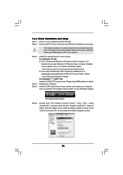
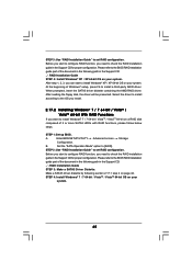
... RAID installation guide in the Support CD for proper configuration. Enter BIOS SETUP UTILITY Advanced screen Storage Configuration. STEP 2: Use "RAID Installation Guide" to [RAID]. After step 1, 2, 3, you want to the BIOS RAID installation guide part of the document in the following path in the Support CD: .. \ RAID Installation Guide STEP 4: Install Windows® XP / XP 64-bit OS on a RAID disk composed of the document in the following section 2.17.1 step 2 on your system. 45 STEP 1: Set up BIOS. Set the "SATA Operation Mode" option to set RAID configuration...
... RAID installation guide in the Support CD for proper configuration. Enter BIOS SETUP UTILITY Advanced screen Storage Configuration. STEP 2: Use "RAID Installation Guide" to [RAID]. After step 1, 2, 3, you want to the BIOS RAID installation guide part of the document in the following path in the Support CD: .. \ RAID Installation Guide STEP 4: Install Windows® XP / XP 64-bit OS on a RAID disk composed of the document in the following section 2.17.1 step 2 on your system. 45 STEP 1: Set up BIOS. Set the "SATA Operation Mode" option to set RAID configuration...
User Manual
Page 51
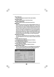
... by default. BIOS SETUP UTILITY Main OC Tweaker Advanced H/W Monitor Boot Security Exit Load Optimized CPU OC Setting [Press Enter] Load Optimized mGPU OC Setting [Press Enter] CPU Configuration Overclock Mode CPU Frequency (MHZ) CPU DOC Frequency (MHZ) PCIE Frequency (MHz) Spread Spectrum Boot Failure Guard Boot Failure Guard Count ASRock UCC CPU Active Core Control [Auto] [200] [Auto] [100] [Auto] [Enabled] [3] [Disabled] [All Cores] Processor Maximum Frequency x10.5 2100 MHZ North Bridge Maximum Frequency x9.0 1800 MHZ Processor Maximum Voltage 1.2500 V Multiplier/Voltage Change...
... by default. BIOS SETUP UTILITY Main OC Tweaker Advanced H/W Monitor Boot Security Exit Load Optimized CPU OC Setting [Press Enter] Load Optimized mGPU OC Setting [Press Enter] CPU Configuration Overclock Mode CPU Frequency (MHZ) CPU DOC Frequency (MHZ) PCIE Frequency (MHz) Spread Spectrum Boot Failure Guard Boot Failure Guard Count ASRock UCC CPU Active Core Control [Auto] [200] [Auto] [100] [Auto] [Enabled] [3] [Disabled] [All Cores] Processor Maximum Frequency x10.5 2100 MHZ North Bridge Maximum Frequency x9.0 1800 MHZ Processor Maximum Voltage 1.2500 V Multiplier/Voltage Change...
User Manual
Page 63
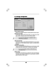
...If SATA6 port is [Enabled]. The default value is used internally, not eSATA, please set this option is for SATA3 support. 63 3.4.4 Storage Configuration BIOS SETUP UTILITY Advanced Storage Configuration Onboard SATA Controller SATA Operation Mode SATA IDE Combined Mode SATA3_6 Mode SATA3_1 SATA3_2 SATA3_3 SATA3_4 SATA3_5 SATA3_6 [Enabled] [IDE] [Enabled] [Gen2] [Hard Disk] [Not Detected] [Not Detected] [Not Detected] [Not Detected] [Not Detected] Configure onboard serial ATA controller. +F1 F9 F10 ESC Select Screen Select Item Change Option General Help Load Defaults Save and...
...If SATA6 port is [Enabled]. The default value is used internally, not eSATA, please set this option is for SATA3 support. 63 3.4.4 Storage Configuration BIOS SETUP UTILITY Advanced Storage Configuration Onboard SATA Controller SATA Operation Mode SATA IDE Combined Mode SATA3_6 Mode SATA3_1 SATA3_2 SATA3_3 SATA3_4 SATA3_5 SATA3_6 [Enabled] [IDE] [Enabled] [Gen2] [Hard Disk] [Not Detected] [Not Detected] [Not Detected] [Not Detected] [Not Detected] Configure onboard serial ATA controller. +F1 F9 F10 ESC Select Screen Select Item Change Option General Help Load Defaults Save and...
User Manual
Page 70
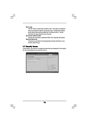
...] and [ASRock]. Currently, the option [Auto] is set or change the supervisor/user password for the system. Boot Up Num-Lock If this section, you enable the option "Full Screen Logo". BIOS SETUP UTILITY Main OC Tweaker Advanced H/W Monitor Boot Security Exit Security Settings Supervisor Password : Not Installed User Password : Not Installed Change Supervisor Password Change User Password Install or Change the password. The default value is [Auto]. Boot Logo Use this item to enable or disable the Boot From Onboard LAN feature. Boot From Onboard LAN Use this option to...
...] and [ASRock]. Currently, the option [Auto] is set or change the supervisor/user password for the system. Boot Up Num-Lock If this section, you enable the option "Full Screen Logo". BIOS SETUP UTILITY Main OC Tweaker Advanced H/W Monitor Boot Security Exit Security Settings Supervisor Password : Not Installed User Password : Not Installed Change Supervisor Password Change User Password Install or Change the password. The default value is [Auto]. Boot Logo Use this item to enable or disable the Boot From Onboard LAN feature. Boot From Onboard LAN Use this option to...
User Manual
Page 72
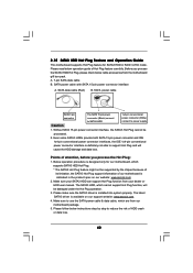
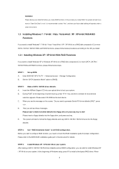
... motherboard contains necessary drivers and useful utilities that the motherboard supports. Because motherboard settings and hardware options vary, use the setup procedures in the Support CD to your CD-ROM drive. Refer to display the menus. 4.2.2 Drivers Menu The Drivers Menu shows the available devices drivers if the system detects the installed devices. 4. Click on the file "ASSETUP.EXE" from the BIN folder in this chapter for more about ASRock, welcome to activate the devices. 4.2.3 Utilities Menu The Utilities Menu...
... motherboard contains necessary drivers and useful utilities that the motherboard supports. Because motherboard settings and hardware options vary, use the setup procedures in the Support CD to your CD-ROM drive. Refer to display the menus. 4.2.2 Drivers Menu The Drivers Menu shows the available devices drivers if the system detects the installed devices. 4. Click on the file "ASSETUP.EXE" from the BIN folder in this chapter for more about ASRock, welcome to activate the devices. 4.2.3 Utilities Menu The Utilities Menu...
Quick Installation Guide
Page 2
... PCI Express 2.0 x1 Slot (PCIE1; Motherboard Layout English 1 PS2_USB_PW1 Jumper 23 Power Switch (PWRBTN) 2 ATX 12V Power Connector (ATX12V1) 24 Front Panel IEEE 1394 Header 3 CPU Heatsink Retention Module (FRONT_1394, White) 4 AM3 CPU Socket 25 Clear CMOS Jumper (CLRCMOS1) 5 Power Fan Connector (PWR_FAN1) 26 USB 2.0 Header (USB12_13, Blue) 6 CPU Fan Connector (CPU_FAN1) 27 USB_PW3 Jumper 7 2 x 240-pin DDR3 DIMM Slots 28 USB 2.0 Header (USB10_11, Blue) (Dual Channel A: DDR3_A1, DDR3_B1; White) 22 Reset Switch (RSTBTN) 43 USB_PW2 Jumper 2 ASRock 880G Extreme3 Motherboard...
... PCI Express 2.0 x1 Slot (PCIE1; Motherboard Layout English 1 PS2_USB_PW1 Jumper 23 Power Switch (PWRBTN) 2 ATX 12V Power Connector (ATX12V1) 24 Front Panel IEEE 1394 Header 3 CPU Heatsink Retention Module (FRONT_1394, White) 4 AM3 CPU Socket 25 Clear CMOS Jumper (CLRCMOS1) 5 Power Fan Connector (PWR_FAN1) 26 USB 2.0 Header (USB12_13, Blue) 6 CPU Fan Connector (CPU_FAN1) 27 USB_PW3 Jumper 7 2 x 240-pin DDR3 DIMM Slots 28 USB 2.0 Header (USB10_11, Blue) (Dual Channel A: DDR3_A1, DDR3_B1; White) 22 Reset Switch (RSTBTN) 43 USB_PW2 Jumper 2 ASRock 880G Extreme3 Motherboard...
Quick Installation Guide
Page 9
... long as a simple switch of your system stability, or even cause damage to change. For audio output, this function because some CPU, including quad-core CPU, can also increase L3 cache size up to 6MB, which allows you implement Dual Channel Memory Technology, make sure to the memory support list on page 38 for USB 2.0 works fine under Windows® 7 / VistaTM / XP. Overclocking may affect your system. CAUTION! 1. This motherboard supports Dual Channel Memory Technology...
... long as a simple switch of your system stability, or even cause damage to change. For audio output, this function because some CPU, including quad-core CPU, can also increase L3 cache size up to 6MB, which allows you implement Dual Channel Memory Technology, make sure to the memory support list on page 38 for USB 2.0 works fine under Windows® 7 / VistaTM / XP. Overclocking may affect your system. CAUTION! 1. This motherboard supports Dual Channel Memory Technology...
Quick Installation Guide
Page 10
... system or damage the CPU. 14. To use FAT32/16/12 file system. 12. The software name itself - With this tool and save the new BIOS file to save your BIOS only in off mode condition. Just launch this utility, you to your USB flash drive, floppy disk or hard drive, then you can update your OC settings as yours! ASRock Instant Flash is capable of overclocking settings. With OC DNA, you...
... system or damage the CPU. 14. To use FAT32/16/12 file system. 12. The software name itself - With this tool and save the new BIOS file to save your BIOS only in off mode condition. Just launch this utility, you to your USB flash drive, floppy disk or hard drive, then you can update your OC settings as yours! ASRock Instant Flash is capable of overclocking settings. With OC DNA, you...
Quick Installation Guide
Page 16
... is enabled, the other one will be disabled. 2. VGA/D-Sub port VGA/DVI-D port HDMI port 2. If you can start to use dual monitor function on this motherboard. DVI-D and HDMI ports cannot function at the same time. When one of both monitors. 16 ASRock 880G Extreme3 Motherboard English When you can drive same or different display contents. Connect DVI-D monitor cable to VGA/DVI-D port on the I/O panel, connect D-Sub monitor cable to VGA/D-Sub port on the I /O panel. This motherboard also provides independent display controllers...
... is enabled, the other one will be disabled. 2. VGA/D-Sub port VGA/DVI-D port HDMI port 2. If you can start to use dual monitor function on this motherboard. DVI-D and HDMI ports cannot function at the same time. When one of both monitors. 16 ASRock 880G Extreme3 Motherboard English When you can drive same or different display contents. Connect DVI-D monitor cable to VGA/DVI-D port on the I/O panel, connect D-Sub monitor cable to VGA/D-Sub port on the I /O panel. This motherboard also provides independent display controllers...
Quick Installation Guide
Page 23
... installing the CATALYST Control Center. Step 2. Please check AMD website for details. Install the required drivers to download it again): http://www.microsoft.com/windowsxp/sp2/default.mspx B. For Windows® XP OS: A. ATI Catalyst Control Center Step 6. Click "View", select "CrossFireXTM", and then check the item "Enable CrossFireXTM". Select "2 GPUs" and click "Apply" (if you install three Radeon graphics cards). English 23 ASRock 880G Extreme3 Motherboard...
... installing the CATALYST Control Center. Step 2. Please check AMD website for details. Install the required drivers to download it again): http://www.microsoft.com/windowsxp/sp2/default.mspx B. For Windows® XP OS: A. ATI Catalyst Control Center Step 6. Click "View", select "CrossFireXTM", and then check the item "Enable CrossFireXTM". Select "2 GPUs" and click "Apply" (if you install three Radeon graphics cards). English 23 ASRock 880G Extreme3 Motherboard...
Quick Installation Guide
Page 36
... adjustment in memory test. ASRock 880G Extreme3 Motherboard Initializes IPL devices controlled by BIOS and option ROMs. Initializes remaining option ROMs. Generate and write contents of the MTRR's. Display errors to limit memory test. Build ACPI tables (if ACPI is supported) Program the peripheral parameters. Enable/Disable NMI as selected Late POST initialization of chipset registers. Updates CMOS memory size from base memory. Prepares the runtime language module. Initialize runtime language module. Prepare CPU for user input at config display if...
... adjustment in memory test. ASRock 880G Extreme3 Motherboard Initializes IPL devices controlled by BIOS and option ROMs. Initializes remaining option ROMs. Generate and write contents of the MTRR's. Display errors to limit memory test. Build ACPI tables (if ACPI is supported) Program the peripheral parameters. Enable/Disable NMI as selected Late POST initialization of chipset registers. Updates CMOS memory size from base memory. Prepares the runtime language module. Initialize runtime language module. Prepare CPU for user input at config display if...
RAID Installation Guide
Page 4
... you create RAID functions. Enter BIOS SETUP UTILITY → Advanced screen →Storage Configuration. B. A. A. Please refer to set RAID configuration, you want to boot your system. When 4 E. STEP 3: Use "RAID Installation Guide" to the BIOS RAID installation guide part in this RAID installation guide for proper configuration. D. Please backup your data first before you will start Please insert a floppy diskette into the floppy drive, and press any key to install Windows XP or Windows XP 64-bit on your system. Insert the ASRock Support CD into...
... you create RAID functions. Enter BIOS SETUP UTILITY → Advanced screen →Storage Configuration. B. A. A. Please refer to set RAID configuration, you want to boot your system. When 4 E. STEP 3: Use "RAID Installation Guide" to the BIOS RAID installation guide part in this RAID installation guide for proper configuration. D. Please backup your data first before you will start Please insert a floppy diskette into the floppy drive, and press any key to install Windows XP or Windows XP 64-bit on your system. Insert the ASRock Support CD into...


