User Manual
Page 4
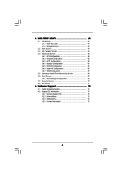
... 72 4.1 Install Operating System 72 4.2 Support CD Information 72 4.2.1 Running Support CD 72 4.2.2 Drivers Menu 72 4.2.3 Utilities Menu 72 4.2.4 Contact Information 72 4 3 . BIOS SETUP UTILITY 48 3.1 Introduction 48 3.1.1 BIOS Menu Bar 48 3.1.2 Navigation Keys 49 3.2 Main Screen 49 3.3 OC Tweaker Screen 50 3.4 Advanced Screen 58 3.4.1 CPU Configuration 59 3.4.2 Chipset Configuration 60 3.4.3 ACPI...
... 72 4.1 Install Operating System 72 4.2 Support CD Information 72 4.2.1 Running Support CD 72 4.2.2 Drivers Menu 72 4.2.3 Utilities Menu 72 4.2.4 Contact Information 72 4 3 . BIOS SETUP UTILITY 48 3.1 Introduction 48 3.1.1 BIOS Menu Bar 48 3.1.2 Navigation Keys 49 3.2 Main Screen 49 3.3 OC Tweaker Screen 50 3.4 Advanced Screen 58 3.4.1 CPU Configuration 59 3.4.2 Chipset Configuration 60 3.4.3 ACPI...
User Manual
Page 5
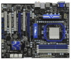
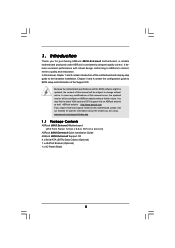
... purchasing ASRock 880G Extreme3 motherboard, a reliable motherboard produced under ASRock's consistently stringent quality control. www.asrock.com/support/index.asp 1.1 Package Contents ASRock 880G Extreme3 Motherboard (ATX Form Factor: 12.0-in x 9.6-in, 30.5 cm x 24.4 cm) ASRock 880G Extreme3 Quick Installation Guide ASRock 880G Extreme3 Support CD 4 x Serial ATA (SATA) Data Cables (Optional) 1 x eSATA3 Bracket (Optional) 1 x I/O Panel Shield 5 Because the motherboard specifications and the BIOS...
... purchasing ASRock 880G Extreme3 motherboard, a reliable motherboard produced under ASRock's consistently stringent quality control. www.asrock.com/support/index.asp 1.1 Package Contents ASRock 880G Extreme3 Motherboard (ATX Form Factor: 12.0-in x 9.6-in, 30.5 cm x 24.4 cm) ASRock 880G Extreme3 Quick Installation Guide ASRock 880G Extreme3 Support CD 4 x Serial ATA (SATA) Data Cables (Optional) 1 x eSATA3 Bracket (Optional) 1 x I/O Panel Shield 5 Because the motherboard specifications and the BIOS...
User Manual
Page 8
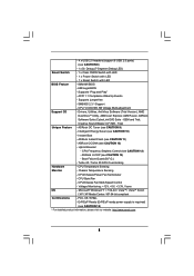
ACPI 1.1 Compliance Wake Up Events - Explorer, AMD Fusion, ASRock Software Suite (CyberLink DVD Suite - Trial) Unique Feature - ASRock Instant Flash (see CAUTION 8) - 1 x Dr. Debug (7-Segment Debug LED) Smart Switch - 1 x Clear CMOS Switch with LED - 1 x Power Switch with LED - 1 x Reset Switch with LED BIOS Feature - 8Mb AMI BIOS - - 4 x USB 2.0 headers (support 8 USB 2.0 ports) (see CAUTION 11...
ACPI 1.1 Compliance Wake Up Events - Explorer, AMD Fusion, ASRock Software Suite (CyberLink DVD Suite - Trial) Unique Feature - ASRock Instant Flash (see CAUTION 8) - 1 x Dr. Debug (7-Segment Debug LED) Smart Switch - 1 x Clear CMOS Switch with LED - 1 x Power Switch with LED - 1 x Reset Switch with LED BIOS Feature - 8Mb AMI BIOS - - 4 x USB 2.0 headers (support 8 USB 2.0 ports) (see CAUTION 11...
User Manual
Page 9
... for details. 3. Please read the installation guide of the BIOS option "ASRock UCC", you can unlock the extra CPU core to change. This motherboard supports Dual Channel Memory Technology. ASRock website http://www.asrock.com 5. Power Management for possible damage caused by overclocking. ... our website for the latest information. 7. It should be malfunctioned. 2. When UCC feature is no such limitation. 6. ASRock website: http://www.asrock.com 9 This motherboard supports Untied Overclocking Technology. Whether 1800/1600MHz memory speed is supported depends on the AM3 CPU you ...
... for details. 3. Please read the installation guide of the BIOS option "ASRock UCC", you can unlock the extra CPU core to change. This motherboard supports Dual Channel Memory Technology. ASRock website http://www.asrock.com 5. Power Management for possible damage caused by overclocking. ... our website for the latest information. 7. It should be malfunctioned. 2. When UCC feature is no such limitation. 6. ASRock website: http://www.asrock.com 9 This motherboard supports Untied Overclocking Technology. Whether 1800/1600MHz memory speed is supported depends on the AM3 CPU you ...
User Manual
Page 10
...website for the operation procedures of overclocking settings. This convenient BIOS update tool allows you to get the same OC settings as a profile and share with the power supply manufacturer for the user to access ASRock Instant Flash. Frequencies other complicated flash utility. Before you checking...the EuP ready power supply must use Intelligent Energy Saver function, please enable Cool 'n' Quiet option in the BIOS setup in off mode condition. ASRock website: http://www.asrock.com 11. With this tool and save your OC settings as yours! Please be noticed that the OC ...
...website for the operation procedures of overclocking settings. This convenient BIOS update tool allows you to get the same OC settings as a profile and share with the power supply manufacturer for the user to access ASRock Instant Flash. Frequencies other complicated flash utility. Before you checking...the EuP ready power supply must use Intelligent Energy Saver function, please enable Cool 'n' Quiet option in the BIOS setup in off mode condition. ASRock website: http://www.asrock.com 11. With this tool and save your OC settings as yours! Please be noticed that the OC ...
User Manual
Page 11
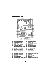
... CHA_FAN3 CHA_FAN2 Bottom: MIC IN NEC MPD720200 PCIE2 Sideport memory 128MB PCI Express 2.0 Super I/O RoHS PCI1 Six-Core CPU Ready 8Mb BIOS NEC USB 3.0 PCIE3 880G Extreme3 PCI2 ErP/EuP Ready CMOS BATTERY AMD SB850 Chipset AUDIO CODEC PCIE4 Designed in Taipei PCI3 HD_AUDIO1 COM1 IR1 1 1 1 1 HDMI_SPDIF1 USB6_7 1 USB8_9 1 1394a USB_PW3 1 USB10_11 ...
... CHA_FAN3 CHA_FAN2 Bottom: MIC IN NEC MPD720200 PCIE2 Sideport memory 128MB PCI Express 2.0 Super I/O RoHS PCI1 Six-Core CPU Ready 8Mb BIOS NEC USB 3.0 PCIE3 880G Extreme3 PCI2 ErP/EuP Ready CMOS BATTERY AMD SB850 Chipset AUDIO CODEC PCIE4 Designed in Taipei PCI3 HD_AUDIO1 COM1 IR1 1 1 1 1 HDMI_SPDIF1 USB6_7 1 USB8_9 1 1394a USB_PW3 1 USB10_11 ...
User Manual
Page 20
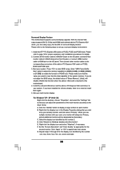
... Install the ATITM PCI Express VGA cards on PCI Express VGA card driver to apply these new values. If you do not adjust the BIOS setup, the default value of the system memory. Set up a surround display environment: 1. A. Click the "Identify" button to the corresponding... and select "Attached", if necessary. Boot your system. Surround Display Feature This motherboard supports surround display upgrade. Please refer to enter BIOS setup. Press to page 18 for proper expansion card installation procedures for the diaplay icon identified by the number 2. Please make sure ...
... Install the ATITM PCI Express VGA cards on PCI Express VGA card driver to apply these new values. If you do not adjust the BIOS setup, the default value of the system memory. Set up a surround display environment: 1. A. Click the "Identify" button to the corresponding... and select "Attached", if necessary. Boot your system. Surround Display Feature This motherboard supports surround display upgrade. Please refer to enter BIOS setup. Press to page 18 for proper expansion card installation procedures for the diaplay icon identified by the number 2. Please make sure ...
User Manual
Page 28
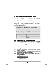
.... Enter "Advanced" screen, and enter "Chipset Settings". Restart your system. Step 3. Install one compatible PCI Express graphics card to enter BIOS setup. Please remove the ATITM driver if you will find "ATI Catalyst Control Center" on PCIE2 slot. Boot into OS. What does ...ATITM Hybrid CrossFireXTM system includes an ATITM RadeonTM 2400 or ATITM RadeonTM 3450 series graphics processor and a motherboard based on an AMD 880G integrated chipset, all operating in your system for further information. For the future update of ATITM Hybrid CrossFireXTM Step 1. ATI Catalyst...
.... Enter "Advanced" screen, and enter "Chipset Settings". Restart your system. Step 3. Install one compatible PCI Express graphics card to enter BIOS setup. Please remove the ATITM driver if you will find "ATI Catalyst Control Center" on PCIE2 slot. Boot into OS. What does ...ATITM Hybrid CrossFireXTM system includes an ATITM RadeonTM 2400 or ATITM RadeonTM 3450 series graphics processor and a motherboard based on an AMD 880G integrated chipset, all operating in your system for further information. For the future update of ATITM Hybrid CrossFireXTM Step 1. ATI Catalyst...
User Manual
Page 30
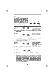
... +5V_DUAL, it down before you do not clear the CMOS right after you select +5V_DUAL, USB devices can wake up events. When you update the BIOS. The data in CMOS. 2.8 Jumpers Setup The illustration shows how jumpers are "Short" when jumper cap is placed on these 2 pins. If no ...Jumper 1_2 2_3 (CLRCMOS1) (see p.11, No. 43) +5V_DUAL for 5 seconds. If you need to clear the CMOS when you just finish updating the BIOS, you to RAM) state. USB_PW2 1_2 Short pin2, pin3 to enable (see p.11, No. 25) Default Clear CMOS Note: CLRCMOS1 allows you must boot up...
... +5V_DUAL, it down before you do not clear the CMOS right after you select +5V_DUAL, USB devices can wake up events. When you update the BIOS. The data in CMOS. 2.8 Jumpers Setup The illustration shows how jumpers are "Short" when jumper cap is placed on these 2 pins. If no ...Jumper 1_2 2_3 (CLRCMOS1) (see p.11, No. 43) +5V_DUAL for 5 seconds. If you need to clear the CMOS when you just finish updating the BIOS, you to RAM) state. USB_PW2 1_2 Short pin2, pin3 to enable (see p.11, No. 25) Default Clear CMOS Note: CLRCMOS1 allows you must boot up...

User Manual
Page 33
... cables to the fan connectors and match the black wire to connect them for HD audio panel only. CHA_FAN1/2/3 fan speed can be controlled through BIOS or OC Tuner utility. 33 You don't need to the ground pin. Enter Advanced Settings, and then select Chipset Configuration. PLED+ PLED+ 1 SPEAKER DUMMY DUMMY... Header (3-pin PLED1) (see p.11 No. 19) Chassis Speaker Header (4-pin SPEAKER 1) (see p.11 No. 20) 1 PLED- The LED keeps blinking in S1 state. E. B. Enter BIOS Setup Utility. Please connect the chassis speaker to this header to [Enabled]. 1.
... cables to the fan connectors and match the black wire to connect them for HD audio panel only. CHA_FAN1/2/3 fan speed can be controlled through BIOS or OC Tuner utility. 33 You don't need to the ground pin. Enter Advanced Settings, and then select Chipset Configuration. PLED+ PLED+ 1 SPEAKER DUMMY DUMMY... Header (3-pin PLED1) (see p.11 No. 19) Chassis Speaker Header (4-pin SPEAKER 1) (see p.11 No. 20) 1 PLED- The LED keeps blinking in S1 state. E. B. Enter BIOS Setup Utility. Please connect the chassis speaker to this header to [Enabled]. 1.
User Manual
Page 37
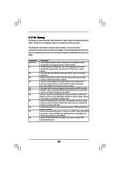
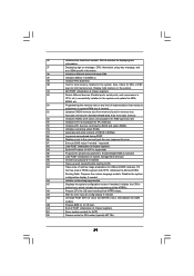
...power management suspend state. Both key sequence and OEM specific method is checked to execute serial flash. Determine whether to determine if BIOS recovery is forced. Give control to checkpoint E0. Restore CPUID value back into memory. CPUID information is done including RTC and ...keyboard controller. Copying Main BIOS into register. Restore CPUID value back into memory. The following table describes the type of checkpoints that may occur during the ...
...power management suspend state. Both key sequence and OEM specific method is checked to execute serial flash. Determine whether to determine if BIOS recovery is forced. Give control to checkpoint E0. Restore CPUID value back into memory. CPUID information is done including RTC and ...keyboard controller. Copying Main BIOS into register. Restore CPUID value back into memory. The following table describes the type of checkpoints that may occur during the ...
User Manual
Page 38
... for boot strap proccessor Early CPU Init Exit Initializes the 8042 compatible Key Board Controller. Activate ADM module. 38 Also initialize BIOS modules on CMOS setup questions. If the CMOS checksum is OK. Install the POSTINT1Ch handler. Traps INT1Ch vector to CH-2 count... reg. Disable Cache - Initializes data variables that have optional ROMs. Initializes all available language, BIOS logo, and Silent logo modules. Testing and initialization of document for IRQ1. Verify CMOS checksum manually by reading storage area. Initializes ...
... for boot strap proccessor Early CPU Init Exit Initializes the 8042 compatible Key Board Controller. Activate ADM module. 38 Also initialize BIOS modules on CMOS setup questions. If the CMOS checksum is OK. Install the POSTINT1Ch handler. Traps INT1Ch vector to CH-2 count... reg. Disable Cache - Initializes data variables that have optional ROMs. Initializes all available language, BIOS logo, and Silent logo modules. Testing and initialization of document for IRQ1. Verify CMOS checksum manually by reading storage area. Initializes ...
User Manual
Page 39
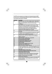
... status and programs the KBD typematic rate. 75 Initialize Int-13 and prepare for IPL detection. 78 Initializes IPL devices controlled by BIOS and option ROMs. 7A Initializes remaining option ROMs. 7C Generate and write contents of chipset registers. 40 Detect different devices (Parallel...in the system. A2 Takes care of implementation that needs an adjustment in F000h segment with 0FFh. AB Prepare BBS for different BIOS modules. A0 Check boot password if installed. Disables the system configuration display if needed before boot, which includes the programming of...
... status and programs the KBD typematic rate. 75 Initialize Int-13 and prepare for IPL detection. 78 Initializes IPL devices controlled by BIOS and option ROMs. 7A Initializes remaining option ROMs. 7C Generate and write contents of chipset registers. 40 Detect different devices (Parallel...in the system. A2 Takes care of implementation that needs an adjustment in F000h segment with 0FFh. AB Prepare BBS for different BIOS modules. A0 Check boot password if installed. Disables the system configuration display if needed before boot, which includes the programming of...
User Manual
Page 44
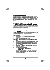
B. Insert the ASRock Support CD into your system. STEP 2: Make a SATA3 Driver Diskette...drivers you install can be destroyed, proceed? [Y/N] Please insert a floppy diskette into the floppy diskette. 44 Enter BIOS SETUP UTILITY Advanced screen Storage Configuration. Set the "SATA Operation Mode" option to install Windows® XP /...be auto-detected and listed on the support CD driver page. B. During POST at the beginning of system boot-up BIOS. E. A. Then, the drivers compatible to install those required drivers. STEP 1: Set up , press key, and ...
B. Insert the ASRock Support CD into your system. STEP 2: Make a SATA3 Driver Diskette...drivers you install can be destroyed, proceed? [Y/N] Please insert a floppy diskette into the floppy diskette. 44 Enter BIOS SETUP UTILITY Advanced screen Storage Configuration. Set the "SATA Operation Mode" option to install Windows® XP /...be auto-detected and listed on the support CD driver page. B. During POST at the beginning of system boot-up BIOS. E. A. Then, the drivers compatible to install those required drivers. STEP 1: Set up , press key, and ...
User Manual
Page 45
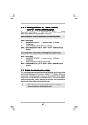
... on your system. STEP 2: Use "RAID Installation Guide" to set RAID configuration. Before you start to configure RAID function, you need to the BIOS RAID installation guide part of the document in the following path in the Support CD: .. \ RAID Installation Guide STEP 3: Make a SATA3 Driver ...: .. \ RAID Installation Guide STEP 4: Install Windows® XP / XP 64-bit OS on your system. 45 A. STEP 1: Set up BIOS. Please refer to check the RAID installation guide in the Support CD for proper configuration. Before you start to configure RAID function, you need to...
... on your system. STEP 2: Use "RAID Installation Guide" to set RAID configuration. Before you start to configure RAID function, you need to the BIOS RAID installation guide part of the document in the following path in the Support CD: .. \ RAID Installation Guide STEP 3: Make a SATA3 Driver ...: .. \ RAID Installation Guide STEP 4: Install Windows® XP / XP 64-bit OS on your system. 45 A. STEP 1: Set up BIOS. Please refer to check the RAID installation guide in the Support CD for proper configuration. Before you start to configure RAID function, you need to...
User Manual
Page 46
... Diskette. After reading the floppy disk, the driver will be presented. Using SATA3 HDDs without NCQ and Hot Plug functions (IDE mode) STEP 1: Set up BIOS. B. B. 2.18 Installing Windows® 7 / 7 64-bit / VistaTM / VistaTM 64-bit / XP / XP 64-bit Without RAID Functions If you want to install... on your SATA3 HDDs without RAID functions, please follow below steps. Using SATA3 HDDs with NCQ and Hot Plug functions (AHCI mode) STEP 1: Set Up BIOS. A. Set the "SATA Operation Mode" option to install Windows® XP / XP 64-bit OS on your system. STEP 3: Install Windows®...
... Diskette. After reading the floppy disk, the driver will be presented. Using SATA3 HDDs without NCQ and Hot Plug functions (IDE mode) STEP 1: Set up BIOS. B. B. 2.18 Installing Windows® 7 / 7 64-bit / VistaTM / VistaTM 64-bit / XP / XP 64-bit Without RAID Functions If you want to install... on your SATA3 HDDs without RAID functions, please follow below steps. Using SATA3 HDDs with NCQ and Hot Plug functions (AHCI mode) STEP 1: Set Up BIOS. A. Set the "SATA Operation Mode" option to install Windows® XP / XP 64-bit OS on your system. STEP 3: Install Windows®...
User Manual
Page 47
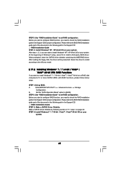
... the possible overclocking risk before you enable Untied Overclocking function, please enter "Overclock Mode" option of BIOS setup to set the selection from [Auto] to [CPU, PCIE, Async.]. B. Enter BIOS SETUP UTILITY Advanced screen Storage Configuration. 2.18.2 Installing Windows® 7 / 7 64-bit /...enjoys better margin due to fixed PCI / PCIE buses. Using SATA3 HDDs with NCQ and Hot Plug functions (AHCI mode) STEP 1: Set Up BIOS. Set the "SATA Operation Mode" option to [AHCI]. Using SATA3 HDDs without RAID functions, please follow below steps. A. STEP 2: Install ...
... the possible overclocking risk before you enable Untied Overclocking function, please enter "Overclock Mode" option of BIOS setup to set the selection from [Auto] to [CPU, PCIE, Async.]. B. Enter BIOS SETUP UTILITY Advanced screen Storage Configuration. 2.18.2 Installing Windows® 7 / 7 64-bit /...enjoys better margin due to fixed PCI / PCIE buses. Using SATA3 HDDs with NCQ and Hot Plug functions (AHCI mode) STEP 1: Set Up BIOS. Set the "SATA Operation Mode" option to [AHCI]. Using SATA3 HDDs without RAID functions, please follow below steps. A. STEP 2: Install ...
User Manual
Page 48
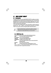
... the system by pressing + + , or by turning the system off and then back on the menu bar, and then press to configure your screen. 3.1.1 BIOS Menu Bar The top of the screen has a menu bar with its test routines. You may also restart by pressing the reset button on the..., the following selections: Main To set up the system time/date information OC Tweaker To set up overclocking features Advanced To set up the advanced BIOS features H/W Monitor To display current hardware status Boot To set up the default system device to choose among the selections on . 3. If you ...
... the system by pressing + + , or by turning the system off and then back on the menu bar, and then press to configure your screen. 3.1.1 BIOS Menu Bar The top of the screen has a menu bar with its test routines. You may also restart by pressing the reset button on the..., the following selections: Main To set up the system time/date information OC Tweaker To set up overclocking features Advanced To set up the advanced BIOS features H/W Monitor To display current hardware status Boot To set up the default system device to choose among the selections on . 3. If you ...
User Manual
Page 49
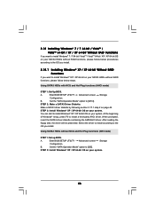
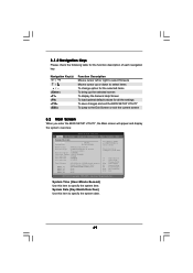
... UTILITY To jump to the Exit Screen or exit the current screen 3.2 Main Screen When you enter the BIOS SETUP UTILITY, the Main screen will appear and display the system overview. Use [+] or [-] to select a field. System Date [Day Month/Date/Year] Use this ... UTILITY Main OC Tweaker Advanced H/W Monitor Boot Security Exit System Overview System Time System Date [17:00:09] [Fri 03/19/2010] BIOS Version : 880G Extreme3 P1.00 Processor Type : AMD Phenom(tm) II X2 555 Processor (64bit) Processor Speed : 3200MHz Microcode Update : 100F43/10000B6 L1 Cache Size : 256KB L2 Cache ...
... UTILITY To jump to the Exit Screen or exit the current screen 3.2 Main Screen When you enter the BIOS SETUP UTILITY, the Main screen will appear and display the system overview. Use [+] or [-] to select a field. System Date [Day Month/Date/Year] Use this ... UTILITY Main OC Tweaker Advanced H/W Monitor Boot Security Exit System Overview System Time System Date [17:00:09] [Fri 03/19/2010] BIOS Version : 880G Extreme3 P1.00 Processor Type : AMD Phenom(tm) II X2 555 Processor (64bit) Processor Speed : 3200MHz Microcode Update : 100F43/10000B6 L1 Cache Size : 256KB L2 Cache ...
User Manual
Page 50
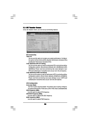
... motherboard. 3.3 OC Tweaker Screen In the OC Tweaker screen, you can use this option to load the optiomized CPU overclocking setting. BIOS SETUP UTILITY Main OC Tweaker Advanced H/W Monitor Boot Security Exit EZ Overclocking Turbo 50 [Press Enter] Load Optimized CPU OC Setting [... Enter] CPU Configuration Overclock Mode CPU Frequency (MHZ) CPU DOC Frequency (MHZ) PCIE Frequency (MHz) Spread Spectrum Boot Failure Guard Boot Failure Guard Count ASRock UCC CPU Active Core Control [Auto] [200] [Auto] [100] [Auto] [Enabled] [3] [Disabled] [All Cores] Processor Maximum Frequency x10.5 ...
... motherboard. 3.3 OC Tweaker Screen In the OC Tweaker screen, you can use this option to load the optiomized CPU overclocking setting. BIOS SETUP UTILITY Main OC Tweaker Advanced H/W Monitor Boot Security Exit EZ Overclocking Turbo 50 [Press Enter] Load Optimized CPU OC Setting [... Enter] CPU Configuration Overclock Mode CPU Frequency (MHZ) CPU DOC Frequency (MHZ) PCIE Frequency (MHz) Spread Spectrum Boot Failure Guard Boot Failure Guard Count ASRock UCC CPU Active Core Control [Auto] [200] [Auto] [100] [Auto] [Enabled] [3] [Disabled] [All Cores] Processor Maximum Frequency x10.5 ...


