
Uk Manual
Page 1
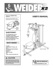
Serial Number Decal QUESTIONS? Write the serial number in this manual before using this manual for future reference. As a manufacturer, we are missing parts or damaged parts, please call: 08457-089009 Or write: ICON Health & Fitness, Ltd. If you have questions, or if there are committed to providing complete customer satisfaction. Save this equipment. WEEMSY70080 Serial No. Unit 4 Revie Road Industrial Estate Revie Road...
Serial Number Decal QUESTIONS? Write the serial number in this manual before using this manual for future reference. As a manufacturer, we are missing parts or damaged parts, please call: 08457-089009 Or write: ICON Health & Fitness, Ltd. If you have questions, or if there are committed to providing complete customer satisfaction. Save this equipment. WEEMSY70080 Serial No. Unit 4 Revie Road Industrial Estate Revie Road...
Uk Manual
Page 2
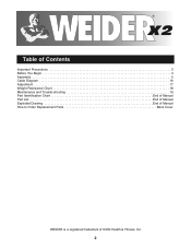
® Table of Contents Important Precautions 3 Before You Begin 4 Assembly 5 Cable Diagram 16 Adjustment 17 Weight Resistance Chart 18 Maintenance and Trouble-shooting 19 Part Identification Chart End of Manual Part List End of Manual Exploded Drawing End of Manual How to Order Replacement Parts Back Cover WEIDER is a registered trademark of ICON Health & Fitness, Inc. 2
® Table of Contents Important Precautions 3 Before You Begin 4 Assembly 5 Cable Diagram 16 Adjustment 17 Weight Resistance Chart 18 Maintenance and Trouble-shooting 19 Part Identification Chart End of Manual Part List End of Manual Exploded Drawing End of Manual How to Order Replacement Parts Back Cover WEIDER is a registered trademark of ICON Health & Fitness, Inc. 2
Uk Manual
Page 3
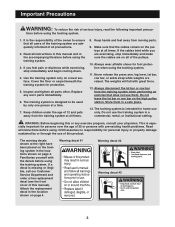
... manual). Never release the press arm, leg lever, lat bar, row bar, or ankle strap while weights are on the pulleys at all times. 8. If a decal is the responsibility of the owner to be used by or through the use them in the accompanying literature before using the training system. 3. It is missing or illegible, call our Customer Service Department and order a free replacement decal (see the front cover...
... manual). Never release the press arm, leg lever, lat bar, row bar, or ankle strap while weights are on the pulleys at all times. 8. If a decal is the responsibility of the owner to be used by or through the use them in the accompanying literature before using the training system. 3. It is missing or illegible, call our Customer Service Department and order a free replacement decal (see the front cover...
Uk Manual
Page 4
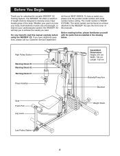
... WEEMSY70080. To help you to the WEIDER® X2 (see the front cover of the body. High Pulley Station Warning Decal #3 Warning Decal #2 Warning Decal #1 Press Handles Assembled Dimensions: Height: 201 cm Width: 109 cm Length: 142 cm Butterfly/Press Arm Backrest Seat Foam Pad Leg Lever Weight Stack Low Pulley Station 4 The serial number can be found on a decal attached to achieve the results you have...
... WEEMSY70080. To help you to the WEIDER® X2 (see the front cover of the body. High Pulley Station Warning Decal #3 Warning Decal #2 Warning Decal #1 Press Handles Assembled Dimensions: Height: 201 cm Width: 109 cm Length: 142 cm Butterfly/Press Arm Backrest Seat Foam Pad Leg Lever Weight Stack Low Pulley Station 4 The serial number can be found on a decal attached to achieve the results you have...
Uk Manual
Page 5
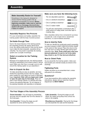
... the Assembly Process Frame Assembly-You will also need grease or petroleum jelly, a small amount of the home gym. Make sure you identify the small parts used . Set Aside Enough Time Due to make assembly as easy as you will go smoothly. By setting aside plenty of the training system, the assembly process will assemble the arms and the leg lever. If a part is enough room to walk...
... the Assembly Process Frame Assembly-You will also need grease or petroleum jelly, a small amount of the home gym. Make sure you identify the small parts used . Set Aside Enough Time Due to make assembly as easy as you will go smoothly. By setting aside plenty of the training system, the assembly process will assemble the arms and the leg lever. If a part is enough room to walk...

Uk Manual
Page 6
... two M8 x 70mm Carriage Bolts (64), a 50mm x 102mm 2 Support Plate (21), and two M8 Nylon Locknuts (70). Open the parts bag labelled "FRAME ASSEMBLY." 35 Press a 50mm Square Cover Cap (35) onto each end 2 of the Front Stabiliser (2). Frame Assembly 1 1. Before you begin this step, make sure that you much more time than it ! Attach the Front Stabiliser (2) to the...
... two M8 x 70mm Carriage Bolts (64), a 50mm x 102mm 2 Support Plate (21), and two M8 Nylon Locknuts (70). Open the parts bag labelled "FRAME ASSEMBLY." 35 Press a 50mm Square Cover Cap (35) onto each end 2 of the Front Stabiliser (2). Frame Assembly 1 1. Before you begin this step, make sure that you much more time than it ! Attach the Front Stabiliser (2) to the...

Uk Manual
Page 7
... Upright (4) onto the M8 x 70mm Carriage Bolts (64) in the bracket on the side shown. Insert the Weight Guides (13) into the lower end of the Weight Bumpers are facing the floor. Slide the nine Weight Plates (36) onto the Weight Guides (13). Slide the Top Weight (17) onto the Weight Guides (13). Insert the Adjustment Tube into the support tube on the Base (1). Press...
... Upright (4) onto the M8 x 70mm Carriage Bolts (64) in the bracket on the side shown. Insert the Weight Guides (13) into the lower end of the Weight Bumpers are facing the floor. Slide the nine Weight Plates (36) onto the Weight Guides (13). Slide the Top Weight (17) onto the Weight Guides (13). Insert the Adjustment Tube into the support tube on the Base (1). Press...
Uk Manual
Page 8
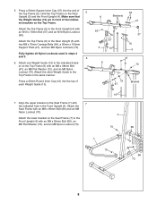
...Seat Frame (7) with an M8 x 38mm Bolt (67), an M8 Flat Washer (72), and an M8 Nylon Locknut (70). Attach the Top Frame (6) to the Top Frame in front of the indicat- Attach the other Weight Guide to the Rear Upright (5) with an M10 x 70mm Bolt (57) and an M10 Nylon Locknut (60). Press... 7 the indicated hole in steps 2 and 3. 6 6. ed brackets on the Seat Frame (7) to the Front Upright (4) with two M8 x 70mm Carriage Bolts (64), a 50mm x 102mm Support Plate (21), and two M8 Nylon Locknuts (70). Attach the lower bracket on the Top Frame. Press a 50mm Square Inner Cap ...
...Seat Frame (7) with an M8 x 38mm Bolt (67), an M8 Flat Washer (72), and an M8 Nylon Locknut (70). Attach the Top Frame (6) to the Top Frame in front of the indicat- Attach the other Weight Guide to the Rear Upright (5) with an M10 x 70mm Bolt (57) and an M10 Nylon Locknut (60). Press... 7 the indicated hole in steps 2 and 3. 6 6. ed brackets on the Seat Frame (7) to the Front Upright (4) with two M8 x 70mm Carriage Bolts (64), a 50mm x 102mm Support Plate (21), and two M8 Nylon Locknuts (70). Attach the lower bracket on the Top Frame. Press a 50mm Square Inner Cap ...
Uk Manual
Page 9
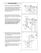
Open the parts bag labelled "ARM ASSEMBLY." Insert the indicated end of the Locking Plate (29) into each end of the Right Arm with the Bolt, two M10 Flat Washers (62), and an M10 Nylon Locknut (60). 60 29 62 Slot 62 4 Lubricate 58 9. Do not overtighten the Nylon Locknut; Press ...the support tube on the Front Upright (4). Attach the Butterfly/Press Frame (9) to the Right Arm (11) with the Bolt, two 10mm Flat Washers (62), and an M10 Nylon Locknut (60). the Butterfly/Press Frame must pivot easily. 37 9 Bracket 37 6 51 Lubricate 10. Wet the lower end of the Right Arm (...
Open the parts bag labelled "ARM ASSEMBLY." Insert the indicated end of the Locking Plate (29) into each end of the Right Arm with the Bolt, two M10 Flat Washers (62), and an M10 Nylon Locknut (60). 60 29 62 Slot 62 4 Lubricate 58 9. Do not overtighten the Nylon Locknut; Press ...the support tube on the Front Upright (4). Attach the Butterfly/Press Frame (9) to the Right Arm (11) with the Bolt, two 10mm Flat Washers (62), and an M10 Nylon Locknut (60). the Butterfly/Press Frame must pivot easily. 37 9 Bracket 37 6 51 Lubricate 10. Wet the lower end of the Right Arm (...

Uk Manual
Page 10
... the Bolt and an M10 Nylon Locknut (60). Attach the Leg Lever (8) to the indicated hole in steps 10 and 11. 11 11 77 79 41 85 9 12. the Leg Lever must pivot easily. 12 38 8 60 7 82 45 Lubricate 57 Cable Assembly 13 13. Open the parts bag labelled "CABLE ASSEMBLY." Identify the Butterfly Cable (47). Wrap the Butterfly Cable around a 90mm Pulley (50...
... the Bolt and an M10 Nylon Locknut (60). Attach the Leg Lever (8) to the indicated hole in steps 10 and 11. 11 11 77 79 41 85 9 12. the Leg Lever must pivot easily. 12 38 8 60 7 82 45 Lubricate 57 Cable Assembly 13 13. Open the parts bag labelled "CABLE ASSEMBLY." Identify the Butterfly Cable (47). Wrap the Butterfly Cable around a 90mm Pulley (50...

Uk Manual
Page 11
...Arm (11). 11 17. Attach the Butterfly 28 Pulley Bracket (26) to a Butterfly Pulley Bracket (26) 16 with the Bolt and an M10 Nylon Locknut. 47 50 54 Slide the loop on the semi-circu- Identify the High Cable (48). Attach the Pulley and two Pulley Covers (28) to the bracket (not shown) on the 28 Front Upright... (4) with an M10 x 50mm Bolt (54), an M10 Flat Washer 60 (62), and an M10 Nylon Locknut (60). Attach the Pulley inside the slot in the direction shown....
...Arm (11). 11 17. Attach the Butterfly 28 Pulley Bracket (26) to a Butterfly Pulley Bracket (26) 16 with the Bolt and an M10 Nylon Locknut. 47 50 54 Slide the loop on the semi-circu- Identify the High Cable (48). Attach the Pulley and two Pulley Covers (28) to the bracket (not shown) on the 28 Front Upright... (4) with an M10 x 50mm Bolt (54), an M10 Flat Washer 60 (62), and an M10 Nylon Locknut (60). Attach the Pulley inside the slot in the direction shown....

Uk Manual
Page 13
...direction shown. Attach the 60 Pulley to the lower half of the Pulley Frame (27) with an M10 x 80mm Bolt (56), an M10 Flat Washer (62), and an M10 Nylon Locknut (60). Wrap the Low Cable (40) around a 90mm Pulley (50) in the Front Upright (4) with the ball 62 under a 90mm Pulley (50) as shown. Attach the Pulley and two Pulley Covers... Route the end of the cable and a ball on the Base (1) with an M10 x 50mm Bolt (54), an M10 Flat Washer (62), and an M10 Nylon Locknut (60). 25 60 1 13 40 62 28 50 28 54 Note that the Cable is between the Pulley and the bracket on the Leg ...
...direction shown. Attach the 60 Pulley to the lower half of the Pulley Frame (27) with an M10 x 80mm Bolt (56), an M10 Flat Washer (62), and an M10 Nylon Locknut (60). Wrap the Low Cable (40) around a 90mm Pulley (50) in the Front Upright (4) with the ball 62 under a 90mm Pulley (50) as shown. Attach the Pulley and two Pulley Covers... Route the end of the cable and a ball on the Base (1) with an M10 x 50mm Bolt (54), an M10 Flat Washer (62), and an M10 Nylon Locknut (60). 25 60 1 13 40 62 28 50 28 54 Note that the Cable is between the Pulley and the bracket on the Leg ...

Uk Manual
Page 14
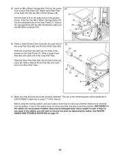
... sure that the cables and the pulleys move smoothly. 71 70 Miscellaneous Assembly 28 28. Attach the M8 x 75mm Eyebolt (69) to the indicated bracket on the end of all pulleys and that the three cables are in the grooves of the Low Cable (40) onto the...Upright (4) with an M10 x 50mm Bolt (54) and an M10 Nylon Locknut (60). 54 28 50 40 25 60 28 27. Open the parts bag labelled "SEAT ASSEMBLY." 26. Attach the Backrest (18) to the lowest holes in the direction shown. Wrap the Low Cable (40) around a 90mm Pulley (50) 26 in the Pulley Plates (25) with 4 two M6 x 65mm Screws...
... sure that the cables and the pulleys move smoothly. 71 70 Miscellaneous Assembly 28 28. Attach the M8 x 75mm Eyebolt (69) to the indicated bracket on the end of all pulleys and that the three cables are in the grooves of the Low Cable (40) onto the...Upright (4) with an M10 x 50mm Bolt (54) and an M10 Nylon Locknut (60). 54 28 50 40 25 60 28 27. Open the parts bag labelled "SEAT ASSEMBLY." 26. Attach the Backrest (18) to the lowest holes in the direction shown. Wrap the Low Cable (40) around a 90mm Pulley (50) 26 in the Pulley Plates (25) with 4 two M6 x 65mm Screws...
Uk Manual
Page 15
... parts will need to make sure that all parts have been properly tightened. If there is any slack in the cables, you will be damaged when heavy weight is in each cable a few times to remove the slack by tightening the cables. Secure the Carriage Bolts with two M6 x 15mm Screws (78). Make sure that the cables move smoothly, find and correct the problem. Turn the Seat...
... parts will need to make sure that all parts have been properly tightened. If there is any slack in the cables, you will be damaged when heavy weight is in each cable a few times to remove the slack by tightening the cables. Secure the Carriage Bolts with two M6 x 15mm Screws (78). Make sure that the cables move smoothly, find and correct the problem. Turn the Seat...
Uk Manual
Page 16
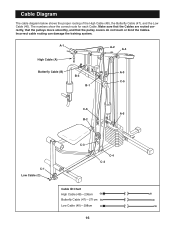
Cable Diagram The cable diagram below shows the proper routing of the High Cable (48), the Butterfly Cable (47), and the Low Cable (40). Make sure that the Cables are routed correctly, that the pulleys move smoothly, and that the pulley covers do not touch or bind the Cables. The numbers show the correct route for each Cable. Incorrect cable routing can damage the training system. A-1 High Cable (A) A-2 A-4 Butterfly Cable (B) A-3 B-3 C-5 B-1 C-6 A-5 B-2 C-1 Low Cable (C) C-3 C-4 C-2 Cable ID Chart High Cable (48)-236cm Butterfly Cable (47)-271cm Low Cable (40)-298cm 16
Cable Diagram The cable diagram below shows the proper routing of the High Cable (48), the Butterfly Cable (47), and the Low Cable (40). Make sure that the Cables are routed correctly, that the pulleys move smoothly, and that the pulley covers do not touch or bind the Cables. The numbers show the correct route for each Cable. Incorrect cable routing can damage the training system. A-1 High Cable (A) A-2 A-4 Butterfly Cable (B) A-3 B-3 C-5 B-1 C-6 A-5 B-2 C-1 Low Cable (C) C-3 C-4 C-2 Cable ID Chart High Cable (48)-236cm Butterfly Cable (47)-271cm Low Cable (40)-298cm 16
Uk Manual
Page 17
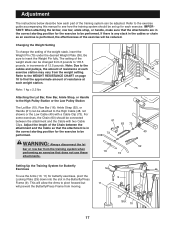
... the Butterfly/Press Frame (9). Adjust the length of the Chain between the attachment and the Cable with a Cable Clip (73). Refer to the exercise guide accompanying this manual to see how the training system should be connected between the attachment and the Cable so that does not use the Arms (10, 11) for each part of resistance at each weight station. IMPORTANT: When attaching the lat bar, row bar, ankle strap, or...
... the Butterfly/Press Frame (9). Adjust the length of the Chain between the attachment and the Cable with a Cable Clip (73). Refer to the exercise guide accompanying this manual to see how the training system should be connected between the attachment and the Cable so that does not use the Arms (10, 11) for each part of resistance at each weight station. IMPORTANT: When attaching the lat bar, row bar, ankle strap, or...
Uk Manual
Page 18
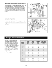
... Butterfly/Press Frame and the Arms to differences in individual weight plates, as well as friction between the cables, pulleys, and weight guides. "Top" refers to the 12.5-lb. Setting Up the Training System for Press Exercises To use of the Weight Guides (13) and secure the Locking Bar with the Lock (24). the other numbers refer to the 6-lb. Note: The actual resistance at each weight station...
... Butterfly/Press Frame and the Arms to differences in individual weight plates, as well as friction between the cables, pulleys, and weight guides. "Top" refers to the 12.5-lb. Setting Up the Training System for Press Exercises To use of the Weight Guides (13) and secure the Locking Bar with the Lock (24). the other numbers refer to the 6-lb. Note: The actual resistance at each weight station...
Uk Manual
Page 19
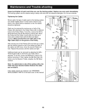
... until the cables are still loose, move the second Pulley one or both of cable used . Maintenance and Trouble-shooting Inspect and tighten all parts each time you use solvents. Tightening the Cables Woven cable, the type of the Pulleys (50) attached to the Pulley Plates (25) to see ORDERING REPLACEMENT PARTS on the training system, can stretch slightly when it is attached. Repeat this , remove the M10 x 50mm Bolt (54) and...
... until the cables are still loose, move the second Pulley one or both of cable used . Maintenance and Trouble-shooting Inspect and tighten all parts each time you use solvents. Tightening the Cables Woven cable, the type of the Pulleys (50) attached to the Pulley Plates (25) to see ORDERING REPLACEMENT PARTS on the training system, can stretch slightly when it is attached. Repeat this , remove the M10 x 50mm Bolt (54) and...
Uk Manual
Page 23
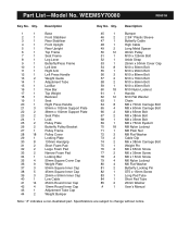
Specifications are subject to change without notice. Part List-Model No. WEEMSY70080 R0601A Key No. Description 1 1 Base 2 1 Front Stabiliser 3 1 Rear Stabiliser 4 1 Front Upright 5 1 Rear Upright 6 1 Top Frame 7 1 Seat Frame 8 1 Leg Lever 9 1 Butterfly/Press Frame 10 1 Left Arm 11 1 Right Arm 12 1 Left Press Handle 13 2 Weight Guide 14 1 Adjustment Tube 15 1 Lat Bar 16 1 Row Bar 17 1 Top Weight 18 1 Backrest 19 1 Seat 20 1 Right Press Handle 21 3 50mm x 102mm Support Plate 22 2 38mm x 102mm Support Plate 23...
Specifications are subject to change without notice. Part List-Model No. WEEMSY70080 R0601A Key No. Description 1 1 Base 2 1 Front Stabiliser 3 1 Rear Stabiliser 4 1 Front Upright 5 1 Rear Upright 6 1 Top Frame 7 1 Seat Frame 8 1 Leg Lever 9 1 Butterfly/Press Frame 10 1 Left Arm 11 1 Right Arm 12 1 Left Press Handle 13 2 Weight Guide 14 1 Adjustment Tube 15 1 Lat Bar 16 1 Row Bar 17 1 Top Weight 18 1 Backrest 19 1 Seat 20 1 Right Press Handle 21 3 50mm x 102mm Support Plate 22 2 38mm x 102mm Support Plate 23...
Uk Manual
Page 25
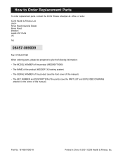
... Replacement Parts To order replacement parts, contact the ICON Fitness Lifestyle Ltd. How to give the following information: • The MODEL NUMBER of the product (WEEMSY70080) • The NAME of the product (WEIDER® X2 training system) • The SERIAL NUMBER of the product (see the front cover of this manual) • The KEY NUMBER and DESCRIPTION of the part(s) (see the PART LIST and EXPLODED DRAWING attached in China © 2001 ICON Health & Fitness...
... Replacement Parts To order replacement parts, contact the ICON Fitness Lifestyle Ltd. How to give the following information: • The MODEL NUMBER of the product (WEEMSY70080) • The NAME of the product (WEIDER® X2 training system) • The SERIAL NUMBER of the product (see the front cover of this manual) • The KEY NUMBER and DESCRIPTION of the part(s) (see the PART LIST and EXPLODED DRAWING attached in China © 2001 ICON Health & Fitness...


