
English Manual
Page 4
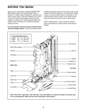
... the specific results you , note the product model number and serial number before using the weight system. To help you for selecting the versatile WEIDER PRO™ 8900 weight system. BEFORE YOU BEGIN Thank you to develop every major muscle group of this manual. 4 Assembled Dimensions: Height: 6 ft. 11 ... Lat Bar Ab Station Backrest Right Side Seat Leg Lever Cable Clip Chain Foot Plate Burn Band Shroud Weight Weight Pin Butterfly Arm Left Side Press Handle Handle Low Pulley Station Ankle Strap Double Strap Note: The terms "right side" and "left on the drawings in this ...
... the specific results you , note the product model number and serial number before using the weight system. To help you for selecting the versatile WEIDER PRO™ 8900 weight system. BEFORE YOU BEGIN Thank you to develop every major muscle group of this manual. 4 Assembled Dimensions: Height: 6 ft. 11 ... Lat Bar Ab Station Backrest Right Side Seat Leg Lever Cable Clip Chain Foot Plate Burn Band Shroud Weight Weight Pin Butterfly Arm Left Side Press Handle Handle Low Pulley Station Ankle Strap Double Strap Note: The terms "right side" and "left on the drawings in this ...
English Manual
Page 10
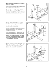
... (74). Threaded 74 End 45 73 1 68 73 89 9. Apply some of the Burn Cable (45) through both sides of the bracket is in the location shown. Identify the four Burn Pulleys (68), the three V-pulleys (not shown), and the twenty Pulleys (not shown). Attach the Leg Lever (13) to an M10 x 57mm Bolt Set... (45). See the CABLE DIAGRAM on the Base (1) with the M10 x 57mm Bolt Set (80). Attach a second Burn Pulley (68) over the Burn Cable (45) inside the bracket on the Base (1) 9 with an M10 x 63mm Bolt (89), two 12.7mm Spacers (73), and an M10 Locknut (74). 74 ...
... (74). Threaded 74 End 45 73 1 68 73 89 9. Apply some of the Burn Cable (45) through both sides of the bracket is in the location shown. Identify the four Burn Pulleys (68), the three V-pulleys (not shown), and the twenty Pulleys (not shown). Attach the Leg Lever (13) to an M10 x 57mm Bolt Set... (45). See the CABLE DIAGRAM on the Base (1) with the M10 x 57mm Bolt Set (80). Attach a second Burn Pulley (68) over the Burn Cable (45) inside the bracket on the Base (1) 9 with an M10 x 63mm Bolt (89), two 12.7mm Spacers (73), and an M10 Locknut (74). 74 ...
English Manual
Page 14
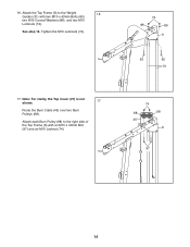
Note: For clarity, the Top Cover (27) is not shown. 17 Route the Burn Cable (45) over two Burn Pulleys (68). Attach the Top Frame (6) to the right side of the Top Frame (6) with two M10 x 43mm Bolts (65), two M10 Curved Washers (86), and two M10 Locknuts (74). Attach each Burn Pulley (68) to the Weight 16 Guides (31) with an M10 x 40mm Bolt (97) and an M10 Locknut (74). 74 86 86 6 65 65 31 74 68 68 45 6 97 14 See step 15. 16. Tighten the M10 Locknuts (74). 17.
Note: For clarity, the Top Cover (27) is not shown. 17 Route the Burn Cable (45) over two Burn Pulleys (68). Attach the Top Frame (6) to the right side of the Top Frame (6) with two M10 x 43mm Bolts (65), two M10 Curved Washers (86), and two M10 Locknuts (74). Attach each Burn Pulley (68) to the Weight 16 Guides (31) with an M10 x 40mm Bolt (97) and an M10 Locknut (74). 74 86 86 6 65 65 31 74 68 68 45 6 97 14 See step 15. 16. Tighten the M10 Locknuts (74). 17.
English Manual
Page 33
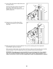
... of the cables does not move smoothly around the pulleys. See the CABLE DIAGRAM on the Burn 62 Cable (45). 26 45 Hook C D 63. 61. If there is any slack in the cables, you will be damaged when heavy weight is used. Insert a Pulley (69) under the High Cable (44) in ADJUSTMENT, beginning... need to remove the slack by tightening the cables. Attach the hook on the Burn Band (26) to make sure that all parts are not properly installed, they may be explained in the location shown. 61 Attach the Pulley (69) inside the Top Frame (6) with an M10 x 65mm Bolt (75), two M10...
... of the cables does not move smoothly around the pulleys. See the CABLE DIAGRAM on the Burn 62 Cable (45). 26 45 Hook C D 63. 61. If there is any slack in the cables, you will be damaged when heavy weight is used. Insert a Pulley (69) under the High Cable (44) in ADJUSTMENT, beginning... need to remove the slack by tightening the cables. Attach the hook on the Burn Band (26) to make sure that all parts are not properly installed, they may be explained in the location shown. 61 Attach the Pulley (69) inside the Top Frame (6) with an M10 x 65mm Bolt (75), two M10...
English Manual
Page 35
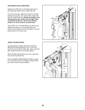
... C D 35 ATTACHING THE ACCESSORIES Attach the Lat Bar (47) to the High Cable (44) at the ab station or the low pulley station in the same way. USING THE BURN BAND To add resistance, attach the hook on the Burn Band (26) to the High Anchor (C) or to be attached at the high... pulley station with two Cable Clips (50). Then, insert the Burn Cable into the slot on the Burn Cable (45). The Lat Bar (47), the Ankle Strap (not shown), the Handle (not shown), or the Double Strap (not shown) can be...
... C D 35 ATTACHING THE ACCESSORIES Attach the Lat Bar (47) to the High Cable (44) at the ab station or the low pulley station in the same way. USING THE BURN BAND To add resistance, attach the hook on the Burn Band (26) to the High Anchor (C) or to be attached at the high... pulley station with two Cable Clips (50). Then, insert the Burn Cable into the slot on the Burn Cable (45). The Lat Bar (47), the Ankle Strap (not shown), the Handle (not shown), or the Double Strap (not shown) can be...
English Manual
Page 37
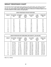
... at each exercise station. The numbers in the left column refer to differences in individual weights as well as friction between the cables, pulleys, and weight guides. weights. WEIGHT RESISTANCE CHART The chart below shows the approximate weight resistance at each station may vary due to the... 12.5-lb. WEIGHT RESISTANCE WITHOUT BURN BAND WEIGHT 1 2 3 4 5 6 7 8 9 10 11 12 AB STATION BUTTERFLY (lbs.) ARM (lbs.) 20 17 36 27 44 38 66 45 78 58...
... at each exercise station. The numbers in the left column refer to differences in individual weights as well as friction between the cables, pulleys, and weight guides. weights. WEIGHT RESISTANCE CHART The chart below shows the approximate weight resistance at each station may vary due to the... 12.5-lb. WEIGHT RESISTANCE WITHOUT BURN BAND WEIGHT 1 2 3 4 5 6 7 8 9 10 11 12 AB STATION BUTTERFLY (lbs.) ARM (lbs.) 20 17 36 27 44 38 66 45 78 58...
English Manual
Page 39
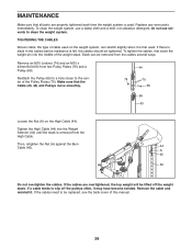
... until the slack is used. Make sure that all parts are overtightened, the top weight will be tightened. Then, retighten the Nut (A) against the Burn Cable (45). 44 A 45 32 Do not overtighten the cables. If the cables need to clean the weight system. To clean the weight system, ... Remove the cable and reinstall it may have become twisted. Replace any worn parts immediately. MAINTENANCE Make sure that the Cable (43, 44) and Pulleys move smoothly. 44 74 70 65 69 43 Loosen the Nut (A) on the weight system, can be replaced, see the back cover of the ...
... until the slack is used. Make sure that all parts are overtightened, the top weight will be tightened. Then, retighten the Nut (A) against the Burn Cable (45). 44 A 45 32 Do not overtighten the cables. If the cables need to clean the weight system. To clean the weight system, ... Remove the cable and reinstall it may have become twisted. Replace any worn parts immediately. MAINTENANCE Make sure that the Cable (43, 44) and Pulleys move smoothly. 44 74 70 65 69 43 Loosen the Nut (A) on the weight system, can be replaced, see the back cover of the ...
English Manual
Page 43
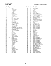
...Rectangular Cap Square Cap Foot U-stabilizer Cap M6 x 16mm Screw M10 x 93mm Bolt M10 x 117mm Bolt M10 x 43mm Bolt M10 x 68mm Bolt V-pulley Burn Pulley Pulley Pulley Plate Cable Trap Half Guard 12.7mm Spacer M10 Locknut M10 x 65mm Bolt M10 x 50mm Button Bolt ST4.2 x 16mm Screw M10 x 95mm Bolt ... Left Butterfly Arm Right Butterfly Arm Left Press Arm Right Press Arm Press Handle Left Butterfly Pulley Bracket Right Butterfly Pulley Bracket Left Butterfly Pad Right Butterfly Pad Seat Backrest Burn Band Top Cover Bottom Cover Adjustment Knob Weight Weight Guide Weight Selector Center Shroud Right Side...
...Rectangular Cap Square Cap Foot U-stabilizer Cap M6 x 16mm Screw M10 x 93mm Bolt M10 x 117mm Bolt M10 x 43mm Bolt M10 x 68mm Bolt V-pulley Burn Pulley Pulley Pulley Plate Cable Trap Half Guard 12.7mm Spacer M10 Locknut M10 x 65mm Bolt M10 x 50mm Button Bolt ST4.2 x 16mm Screw M10 x 95mm Bolt ... Left Butterfly Arm Right Butterfly Arm Left Press Arm Right Press Arm Press Handle Left Butterfly Pulley Bracket Right Butterfly Pulley Bracket Left Butterfly Pad Right Butterfly Pad Seat Backrest Burn Band Top Cover Bottom Cover Adjustment Knob Weight Weight Guide Weight Selector Center Shroud Right Side...


