
English Manual
Page 1
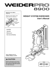
Model No. 831.14923.1 Serial No. Write the serial number in this manual before using this manual for reference. Serial Number Decal WEIGHT SYSTEM EXERCISER Userʼs Manual • Assembly • Operation • Maintenance • Part List and Drawing Sears, Roebuck and Co. Keep this equipment. Hoffman Estates, IL 60179 CAUTION Read all precautions and instructions in the space above for future reference.
Model No. 831.14923.1 Serial No. Write the serial number in this manual before using this manual for reference. Serial Number Decal WEIGHT SYSTEM EXERCISER Userʼs Manual • Assembly • Operation • Maintenance • Part List and Drawing Sears, Roebuck and Co. Keep this equipment. Hoffman Estates, IL 60179 CAUTION Read all precautions and instructions in the space above for future reference.

English Manual
Page 2
... PRECAUTIONS 3 BEFORE YOU BEGIN 4 PART IDENTIFICATION CHART 5 ASSEMBLY 7 ADJUSTMENT 34 WEIGHT RESISTANCE CHART 37 CABLE DIAGRAM 38 MAINTENANCE 39 EXERCISE GUIDELINES 40 PART LIST 43 EXPLODED DRAWING 45 ORDERING REPLACEMENT PARTS Back Cover 90-DAY FULL WARRANTY Back Cover WARNING DECAL PLACEMENT This drawing shows the location(s) of the warning decal(s). Note: The decal(s) may not be shown at actual size. 2 Apply the decal in the location shown. If a decal is...
... PRECAUTIONS 3 BEFORE YOU BEGIN 4 PART IDENTIFICATION CHART 5 ASSEMBLY 7 ADJUSTMENT 34 WEIGHT RESISTANCE CHART 37 CABLE DIAGRAM 38 MAINTENANCE 39 EXERCISE GUIDELINES 40 PART LIST 43 EXPLODED DRAWING 45 ORDERING REPLACEMENT PARTS Back Cover 90-DAY FULL WARRANTY Back Cover WARNING DECAL PLACEMENT This drawing shows the location(s) of the warning decal(s). Note: The decal(s) may not be shown at actual size. 2 Apply the decal in the location shown. If a decal is...
English Manual
Page 3
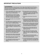
... institutional setting. 5. Replace any exercise program, consult your weight sys- Make sure that could cause the weight system to ensure that the cables are raised. Never release the arms, leg lever, lat bar, handle, ankle strap, or double strap while weights are on the pulleys. 14. IMPORTANT PRECAUTIONS WARNING: To reduce the risk of serious injury, read all important precautions and instructions in this manual and all...
... institutional setting. 5. Replace any exercise program, consult your weight sys- Make sure that could cause the weight system to ensure that the cables are raised. Never release the arms, leg lever, lat bar, handle, ankle strap, or double strap while weights are on the pulleys. 14. IMPORTANT PRECAUTIONS WARNING: To reduce the risk of serious injury, read all important precautions and instructions in this manual and all...
English Manual
Page 4
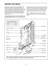
... Seat Leg Lever Cable Clip Chain Foot Plate Burn Band Shroud Weight Weight Pin Butterfly Arm Left Side Press Handle Handle Low Pulley Station Ankle Strap Double Strap Note: The terms "right side" and "left side" are used relative to tone your body, build dramatic muscle size and strength, or improve your benefit, read this manual. 4 BEFORE YOU BEGIN Thank you , note the product model number and serial number...
... Seat Leg Lever Cable Clip Chain Foot Plate Burn Band Shroud Weight Weight Pin Butterfly Arm Left Side Press Handle Handle Low Pulley Station Ankle Strap Double Strap Note: The terms "right side" and "left side" are used relative to tone your body, build dramatic muscle size and strength, or improve your benefit, read this manual. 4 BEFORE YOU BEGIN Thank you , note the product model number and serial number...

English Manual
Page 5
PART IDENTIFICATION CHART Refer to the drawings below to see if it has been preassembled. To avoid damaging parts, do not use power tools for assembly. ST4.2 x 19mm Screw (90) 6.35mm Spacer (94) 12.7mm Spacer (73) 14.8mm Spacer (95) M10 Washer (88) M4 Locknut (108) ...page 6 M10 Curved Washer (86) 5 The number in assembly. IMPORTANT: If you cannot find a part in the hardware kit, check to identify small parts used in parentheses by each drawing is missing, please call 1-877-992-5999. If a part is the key number of the part, from the PART LIST near the end of this manual.
PART IDENTIFICATION CHART Refer to the drawings below to see if it has been preassembled. To avoid damaging parts, do not use power tools for assembly. ST4.2 x 19mm Screw (90) 6.35mm Spacer (94) 12.7mm Spacer (73) 14.8mm Spacer (95) M10 Washer (88) M4 Locknut (108) ...page 6 M10 Curved Washer (86) 5 The number in assembly. IMPORTANT: If you cannot find a part in the hardware kit, check to identify small parts used in parentheses by each drawing is missing, please call 1-877-992-5999. If a part is the key number of the part, from the PART LIST near the end of this manual.
English Manual
Page 7
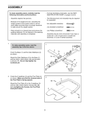
... small parts, use the PART IDENTIFICATION CHART on pages 5 and 6. • The following information and instructions: • Assembly requires two persons. • Because of its weight and size, assemble the weight system in the location where it will be more convenient if you have a socket set, a set of open-end or closed-end wrenches, or a set of the packing materials until assembly is facing upward. 82 3 Attach the...
... small parts, use the PART IDENTIFICATION CHART on pages 5 and 6. • The following information and instructions: • Assembly requires two persons. • Because of its weight and size, assemble the weight system in the location where it will be more convenient if you have a socket set, a set of open-end or closed-end wrenches, or a set of the packing materials until assembly is facing upward. 82 3 Attach the...
English Manual
Page 10
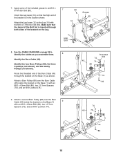
... as you assemble them. 8 Identify the Burn Cable (45). Route the threaded end of the Burn Cable (45) through both sides of the bracket is inserted through the bracket on the Leg. 80 13 Grease 80 10 High End 8. See the CABLE DIAGRAM on the Base (1) 9 with an M10 x 63mm Bolt (89), ...73 89 10 7. Apply some of the included grease to identify the cables as shown. Attach a second Burn Pulley (68) over the Burn Cable (45) inside the bracket on page 38 to an M10 x 57mm Bolt Set (80). 7 Orient the Leg Lever (13) so that the barrel of the Bolt Set is in the location shown.
... as you assemble them. 8 Identify the Burn Cable (45). Route the threaded end of the Burn Cable (45) through both sides of the bracket is inserted through the bracket on the Leg. 80 13 Grease 80 10 High End 8. See the CABLE DIAGRAM on the Base (1) 9 with an M10 x 63mm Bolt (89), ...73 89 10 7. Apply some of the included grease to identify the cables as shown. Attach a second Burn Pulley (68) over the Burn Cable (45) inside the bracket on page 38 to an M10 x 57mm Bolt Set (80). 7 Orient the Leg Lever (13) so that the barrel of the Bolt Set is in the location shown.
English Manual
Page 18
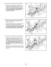
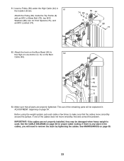
... 26. Attach the Pulley (69) and a Cable Trap (71) to hold the Low Cable in step 25, an M10 Washer (88), and an M10 Locknut (74). Set the Low Cable aside until step 38. 69 43 71 5 83 18 17 88 74 18 Route the Low Cable (43)...Attach the Pulley (69) and a Cable Trap (71) inside the Left and Right Press Arms (17, 18) with an M10 x 47mm Bolt (91) and an M10 Locknut (74). Route the Low Cable (43) over a Pulley (69). 25 Attach the Pulley (69) and a Cable Trap (71) inside the Left and Right Press Arms (17, 18) with the M10 x 125mm Bolt (83) used in the groove of the Upright...
... 26. Attach the Pulley (69) and a Cable Trap (71) to hold the Low Cable in step 25, an M10 Washer (88), and an M10 Locknut (74). Set the Low Cable aside until step 38. 69 43 71 5 83 18 17 88 74 18 Route the Low Cable (43)...Attach the Pulley (69) and a Cable Trap (71) inside the Left and Right Press Arms (17, 18) with an M10 x 47mm Bolt (91) and an M10 Locknut (74). Route the Low Cable (43) over a Pulley (69). 25 Attach the Pulley (69) and a Cable Trap (71) inside the Left and Right Press Arms (17, 18) with the M10 x 125mm Bolt (83) used in the groove of the Upright...
English Manual
Page 19
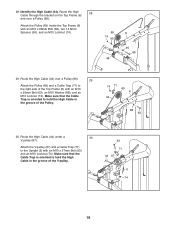
28. Route the High Cable (44) over a Pulley (69). Identify the High Cable (44). Make sure that the Cable Trap is oriented to the Upright (5) with an M10 x 68mm Bolt (66), two 14.8mm Spacers (95), and an M10 Locknut (74). 69 74 95 44 6 95 66 29. Route the High Cable (44) under a 30 V-pulley (67). Attach the V-pulley (67) and a Cable Trap...
28. Route the High Cable (44) over a Pulley (69). Identify the High Cable (44). Make sure that the Cable Trap is oriented to the Upright (5) with an M10 x 68mm Bolt (66), two 14.8mm Spacers (95), and an M10 Locknut (74). 69 74 95 44 6 95 66 29. Route the High Cable (44) under a 30 V-pulley (67). Attach the V-pulley (67) and a Cable Trap...
English Manual
Page 21
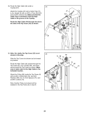
... this step. 35 Slide the Top Cover (not shown) as far forward as possible. Route the High Cable (44) upward through the Top Frame (6), over a Pulley (69), and downward through the slot in the side of the V-pulley. Route the High Cable (44) under a V-pulley (67). 34 Attach the V-pulley (67) and a Cable Trap (71) to the Upright (5) with an M10 x 65mm Bolt (75...
... this step. 35 Slide the Top Cover (not shown) as far forward as possible. Route the High Cable (44) upward through the Top Frame (6), over a Pulley (69), and downward through the slot in the side of the V-pulley. Route the High Cable (44) under a V-pulley (67). 34 Attach the V-pulley (67) and a Cable Trap (71) to the Upright (5) with an M10 x 65mm Bolt (75...
English Manual
Page 33
... properly tightened. Before using the weight system, pull each cable a few times to remove the slack by tightening the cables. 61. See MAINTENANCE on page 34. If one of the remaining parts will need to make sure that all parts are not properly installed, they may be explained in the location shown. 61 Attach the Pulley (69) inside the Top Frame (6) with an M10 x 65mm Bolt...
... properly tightened. Before using the weight system, pull each cable a few times to remove the slack by tightening the cables. 61. See MAINTENANCE on page 34. If one of the remaining parts will need to make sure that all parts are not properly installed, they may be explained in the location shown. 61 Attach the Pulley (69) inside the Top Frame (6) with an M10 x 65mm Bolt...
English Manual
Page 34
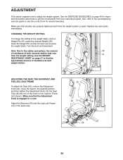
... the cables and pulleys, the amount 30 of resistance at each exercise station may vary from your exercise program. ADJUSTING THE SEAT, THE BACKREST, AND THE LEG LOCK FRAME To adjust the Seat (24), remove the Adjustment Knob (29), move the Seat to get the most benefit from the weight setting. CHANGING THE WEIGHT SETTING To change the setting of the holes in the Cushion Frame (not shown). Insert the Weight Pin so that all parts...
... the cables and pulleys, the amount 30 of resistance at each exercise station may vary from your exercise program. ADJUSTING THE SEAT, THE BACKREST, AND THE LEG LOCK FRAME To adjust the Seat (24), remove the Adjustment Knob (29), move the Seat to get the most benefit from the weight setting. CHANGING THE WEIGHT SETTING To change the setting of the holes in the Cushion Frame (not shown). Insert the Weight Pin so that all parts...
English Manual
Page 35
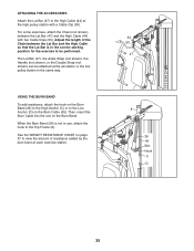
...Adjust the length of resistance added by the burn band at each exercise station. 44 50 47 6 26 45 Slot Hook C D 35 When the Burn Band (26) is in the correct starting position for the exercise to be attached at the ab station or the low pulley station in use, attach the hook to the Top Frame (6). See the WEIGHT RESISTANCE CHART... on the Burn Cable (45). The Lat Bar (47), the Ankle Strap (not shown),...
...Adjust the length of resistance added by the burn band at each exercise station. 44 50 47 6 26 45 Slot Hook C D 35 When the Burn Band (26) is in the correct starting position for the exercise to be attached at the ab station or the low pulley station in use, attach the hook to the Top Frame (6). See the WEIGHT RESISTANCE CHART... on the Burn Cable (45). The Lat Bar (47), the Ankle Strap (not shown),...
English Manual
Page 37
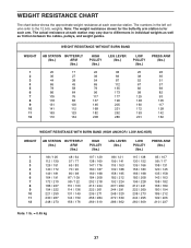
... numbers in individual weights as well as friction between the cables, pulleys, and weight guides. weights. The actual resistance at each exercise station. WEIGHT RESISTANCE WITHOUT BURN BAND WEIGHT 1 2 3 4 5 6 7 8 9 10 11 12 AB STATION BUTTERFLY (lbs.) ARM (lbs.) 20 17 36 27 44 38 66 45 78 58 86 64 105 76 118 83 131 100 141 112 163 123 172 134 HIGH PULLEY...
... numbers in individual weights as well as friction between the cables, pulleys, and weight guides. weights. The actual resistance at each exercise station. WEIGHT RESISTANCE WITHOUT BURN BAND WEIGHT 1 2 3 4 5 6 7 8 9 10 11 12 AB STATION BUTTERFLY (lbs.) ARM (lbs.) 20 17 36 27 44 38 66 45 78 58 86 64 105 76 118 83 131 100 141 112 163 123 172 134 HIGH PULLEY...
English Manual
Page 39
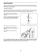
... slack in the cables before resistance is first used. Slack can stretch slightly when it is felt, the cables should be replaced, see the back cover of cable used . If the cables need to clean the weight system. Replace any worn parts immediately. If the cables are properly tightened each time the weight system is removed from two Pulley Plates (70) and a Pulley (69). TIGHTENING THE CABLES Woven cable, the type of...
... slack in the cables before resistance is first used. Slack can stretch slightly when it is felt, the cables should be replaced, see the back cover of cable used . If the cables need to clean the weight system. Replace any worn parts immediately. If the cables are properly tightened each time the weight system is removed from two Pulley Plates (70) and a Pulley (69). TIGHTENING THE CABLES Woven cable, the type of...
English Manual
Page 40
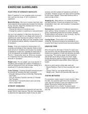
... to your muscles by using high amounts of resistance. Use your own judgment to your body time to 10 different exercises in each workout. To achieve good results, make exercise a regular and enjoyable part of your weight and key body measurements once a month. Adjust the intensity level of an individual exercise as follows: • Change the amount of resistance used , and the numbers of sets and repetitions completed...
... to your muscles by using high amounts of resistance. Use your own judgment to your body time to 10 different exercises in each workout. To achieve good results, make exercise a regular and enjoyable part of your weight and key body measurements once a month. Adjust the intensity level of an individual exercise as follows: • Change the amount of resistance used , and the numbers of sets and repetitions completed...
English Manual
Page 41
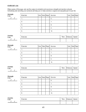
... strength and aerobic workouts. Sets Reps Exercise 6. 7. 8. 9. 10. Aerobic Date: Exercise Time Distance Speed Strength Date: Aerobic Date: Exercise 1. 2. 3. 4. 5. Lbs. Sets Reps Time Distance Speed 41 Lbs. Sets Reps Exercise 6. 7. 8. 9. 10. Scheduling and recording your workouts will help you to make exercise a regular and enjoyable part of this page, and use the copies to schedule and record your life. Sets Reps Exercise 6. Sets Reps 2. 7. 3. 8. 4. 9. 5. 10. Exercise Lbs. Lbs. Exercise Lbs. Strength...
... strength and aerobic workouts. Sets Reps Exercise 6. 7. 8. 9. 10. Aerobic Date: Exercise Time Distance Speed Strength Date: Aerobic Date: Exercise 1. 2. 3. 4. 5. Lbs. Sets Reps Time Distance Speed 41 Lbs. Sets Reps Exercise 6. 7. 8. 9. 10. Scheduling and recording your workouts will help you to make exercise a regular and enjoyable part of this page, and use the copies to schedule and record your life. Sets Reps Exercise 6. Sets Reps 2. 7. 3. 8. 4. 9. 5. 10. Exercise Lbs. Lbs. Exercise Lbs. Strength...
English Manual
Page 43
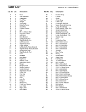
... Frame Leg M10 x 130mm Bolt Leg Lock Frame Leg Lever Burn Bracket Left Butterfly Arm Right Butterfly Arm Left Press Arm Right Press Arm Press Handle Left Butterfly Pulley Bracket Right Butterfly Pulley Bracket Left Butterfly Pad Right Butterfly Pad Seat Backrest Burn Band Top Cover Bottom Cover Adjustment Knob Weight Weight Guide Weight Selector Center Shroud Right Side Shroud Foam Pad Pad Cap Roll Pin Lock Lock Pin Bumper Weight Pin Press Arm Spacer Low Cable High Cable Burn Cable Model...
... Frame Leg M10 x 130mm Bolt Leg Lock Frame Leg Lever Burn Bracket Left Butterfly Arm Right Butterfly Arm Left Press Arm Right Press Arm Press Handle Left Butterfly Pulley Bracket Right Butterfly Pulley Bracket Left Butterfly Pad Right Butterfly Pad Seat Backrest Burn Band Top Cover Bottom Cover Adjustment Knob Weight Weight Guide Weight Selector Center Shroud Right Side Shroud Foam Pad Pad Cap Roll Pin Lock Lock Pin Bumper Weight Pin Press Arm Spacer Low Cable High Cable Burn Cable Model...
English Manual
Page 44
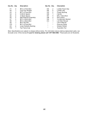
... to change without notice. Lat Bar Foam Grip Lat Bar Cap Plastic Bushing Handle M4 x 12mm Bolt M4 Locknut Containment Bracket Left Side Shroud Userʼs Manual Exercise Guide Grease Packet Assembly Tool Note: Specifications are not illustrated. 44 For information about ordering replacement parts, see the back cover of this manual. Qty. Description 91 3 92 1 93 2 94 2 95 2 96 2 97 2 98 1 99 1 100 1 101 2 102 1 M10 x 47mm Bolt Leg...
... to change without notice. Lat Bar Foam Grip Lat Bar Cap Plastic Bushing Handle M4 x 12mm Bolt M4 Locknut Containment Bracket Left Side Shroud Userʼs Manual Exercise Guide Grease Packet Assembly Tool Note: Specifications are not illustrated. 44 For information about ordering replacement parts, see the back cover of this manual. Qty. Description 91 3 92 1 93 2 94 2 95 2 96 2 97 2 98 1 99 1 100 1 101 2 102 1 M10 x 47mm Bolt Leg...

English Manual
Page 48
For the replacement parts, accessories, and user's manuals that you may also have other rights which vary from state to arrange for free repair (or replacement if repair proves impossible). This warranty gives you specific legal rights, and you need to do-it fixed, at your home or ours! Get it -yourself. For Sears professional installation of all major brand appliances, lawn and garden equipment, or...
For the replacement parts, accessories, and user's manuals that you may also have other rights which vary from state to arrange for free repair (or replacement if repair proves impossible). This warranty gives you specific legal rights, and you need to do-it fixed, at your home or ours! Get it -yourself. For Sears professional installation of all major brand appliances, lawn and garden equipment, or...


