
English Manual
Page 1
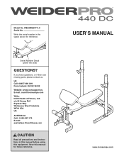
... the serial number in this manual before using this manual for reference. Serial Number Decal (under the seat) QUESTIONS? If you have questions, or if there are missing parts, please contact us: UK Call: 08457 089 009 From Ireland: 053 92 36102 Website: www.iconsupport.eu E-mail: [email protected] Write: ICON Health & Fitness, Ltd. Save this equipment. USERʼS MANUAL www.iconeurope.com Model...
... the serial number in this manual before using this manual for reference. Serial Number Decal (under the seat) QUESTIONS? If you have questions, or if there are missing parts, please contact us: UK Call: 08457 089 009 From Ireland: 053 92 36102 Website: www.iconsupport.eu E-mail: [email protected] Write: ICON Health & Fitness, Ltd. Save this equipment. USERʼS MANUAL www.iconeurope.com Model...
English Manual
Page 2
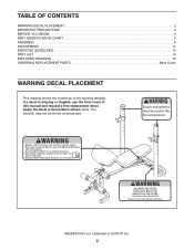
Apply the decal in the location shown. WEIDER PRO is missing or illegible, see the front cover of ICON IP, Inc. 2 Note: The decal(s) may not be shown at actual size. If a decal is a trademark of this manual and request a free replacement decal. TABLE OF CONTENTS WARNING DECAL PLACEMENT 2 IMPORTANT PRECAUTIONS 3 BEFORE YOU BEGIN 4 PART IDENTIFICATION CHART 5 ASSEMBLY 6 ADJUSTMENT 11 EXERCISE GUIDELINES 13 PART LIST 14 EXPLODED DRAWING 15 ORDERING REPLACEMENT PARTS Back Cover WARNING DECAL PLACEMENT This drawing shows the location(s) of the warning decal(s).
Apply the decal in the location shown. WEIDER PRO is missing or illegible, see the front cover of ICON IP, Inc. 2 Note: The decal(s) may not be shown at actual size. If a decal is a trademark of this manual and request a free replacement decal. TABLE OF CONTENTS WARNING DECAL PLACEMENT 2 IMPORTANT PRECAUTIONS 3 BEFORE YOU BEGIN 4 PART IDENTIFICATION CHART 5 ASSEMBLY 6 ADJUSTMENT 11 EXERCISE GUIDELINES 13 PART LIST 14 EXPLODED DRAWING 15 ORDERING REPLACEMENT PARTS Back Cover WARNING DECAL PLACEMENT This drawing shows the location(s) of the warning decal(s).
English Manual
Page 3
... on the leg lever. Replace any exercise program, consult your physician. Do not place more than 210 lbs (95 kg), including a barbell, on the weight rests. Always keep hands and feet away from moving parts. 12. When you perform the bench press exercise, your weight bench. Before beginning any worn parts immediately. 8. Use the weight bench only as described in a commercial, rental, or institutional setting. 5. The weight bench is...
... on the leg lever. Replace any exercise program, consult your physician. Do not place more than 210 lbs (95 kg), including a barbell, on the weight rests. Always keep hands and feet away from moving parts. 12. When you perform the bench press exercise, your weight bench. Before beginning any worn parts immediately. 8. Use the weight bench only as described in a commercial, rental, or institutional setting. 5. The weight bench is...
English Manual
Page 4
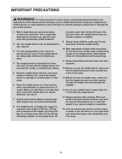
... location of the serial number decal are labeled. BEFORE YOU BEGIN Thank you want. The 440 DC Midwidth weight bench offers a selection of exercise stations designed to achieve the specific results you for selecting the versatile WEIDER PRO™ 440 DC Mid-width weight bench. Before reading further, please review the drawing below and familiarize yourself with the parts that are shown on the front cover...
... location of the serial number decal are labeled. BEFORE YOU BEGIN Thank you want. The 440 DC Midwidth weight bench offers a selection of exercise stations designed to achieve the specific results you for selecting the versatile WEIDER PRO™ 440 DC Mid-width weight bench. Before reading further, please review the drawing below and familiarize yourself with the parts that are shown on the front cover...
English Manual
Page 5
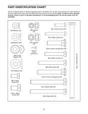
... damaging parts, do not use power tools for assembly. PART IDENTIFICATION CHART See the drawings below to identify small parts used in parentheses by each drawing is not in the hardware kit, check to see if it has been preattached. The number in assembly. Note: If a part is the key number of the part, from the PART LIST near the end of this manual. M10 x 180mm Bolt (43...
... damaging parts, do not use power tools for assembly. PART IDENTIFICATION CHART See the drawings below to identify small parts used in parentheses by each drawing is not in the hardware kit, check to see if it has been preattached. The number in assembly. Note: If a part is the key number of the part, from the PART LIST near the end of this manual. M10 x 180mm Bolt (43...
English Manual
Page 6
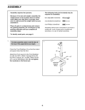
... all parts in the location where it will be used. Orient the Front Stabilizer (2) so that there is enough clearance to the Front Stabilizer (2) with two M10 x 67mm Carriage Bolts (34), two M10 Locknuts (37), an M8 x 48mm Screw (47), and an M8 Washer (48). Attach the Front Leg (4) to walk around the weight bench as you have a socket set, a set of open...
... all parts in the location where it will be used. Orient the Front Stabilizer (2) so that there is enough clearance to the Front Stabilizer (2) with two M10 x 67mm Carriage Bolts (34), two M10 Locknuts (37), an M8 x 48mm Screw (47), and an M8 Washer (48). Attach the Front Leg (4) to walk around the weight bench as you have a socket set, a set of open...
English Manual
Page 7
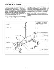
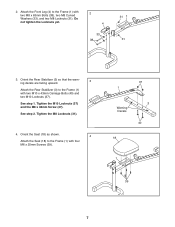
See step 1. Tighten the M8 Locknuts (31). 4. Orient the Rear Stabilizer (3) so that the warning decals are facing upward. 3 Attach the Rear Stabilizer (3) to the Frame (1) with four M6 x 25mm Screws (39). 37 1 Warning Decals 3 40 18 1 39 7 See step 2. Orient the Seat (18) as shown. 4 Attach the Seat (18) to the Frame (1) with two M8 x 63mm Bolts (38), two M8 Curved...
See step 1. Tighten the M8 Locknuts (31). 4. Orient the Rear Stabilizer (3) so that the warning decals are facing upward. 3 Attach the Rear Stabilizer (3) to the Frame (1) with four M6 x 25mm Screws (39). 37 1 Warning Decals 3 40 18 1 39 7 See step 2. Orient the Seat (18) as shown. 4 Attach the Seat (18) to the Frame (1) with two M8 x 63mm Bolts (38), two M8 Curved...
English Manual
Page 8
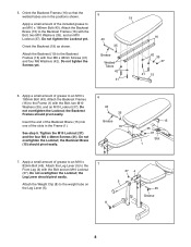
... the Locknut; See step 5. Attach the Leg Lever (5) to the Backrest Frames (16) with the Bolt and an M10 Locknut (37). Attach the Weight Clip (8) to an M10 x 180mm Bolt (43). Do not tighten the Locknut yet. 43 16 Orient the Backrest (19) as shown. 35 Attach the Backrest (19) to the 7 Front Leg (4) with four M6 x 48mm Screws (41) and...
... the Locknut; See step 5. Attach the Leg Lever (5) to the Backrest Frames (16) with the Bolt and an M10 Locknut (37). Attach the Weight Clip (8) to an M10 x 180mm Bolt (43). Do not tighten the Locknut yet. 43 16 Orient the Backrest (19) as shown. 35 Attach the Backrest (19) to the 7 Front Leg (4) with four M6 x 48mm Screws (41) and...
English Manual
Page 9
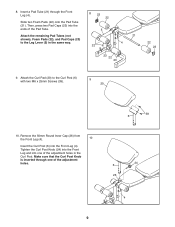
...25mm Screws (39). 9 20 10. Remove the 50mm Round Inner Cap (26) from the Front Leg (4). 10 Insert the Curl Post (6) into the ends of the Pad Tube. 8. Then, press two Pad Caps (23) into the Front Leg (4). Slide two Foam Pads (22) onto the Pad Tube (21). Make sure that the Curl Post Knob ...is inserted through the Front Leg (4). Attach the Curl Pad (20) to the Leg Lever (5) in the Curl Post. Tighten the Curl Post Knob (24) into the Front Leg and into one of the adjustment holes in the same way. 8 23 22 5 22 21 4 ...
...25mm Screws (39). 9 20 10. Remove the 50mm Round Inner Cap (26) from the Front Leg (4). 10 Insert the Curl Post (6) into the ends of the Pad Tube. 8. Then, press two Pad Caps (23) into the Front Leg (4). Slide two Foam Pads (22) onto the Pad Tube (21). Make sure that the Curl Post Knob ...is inserted through the Front Leg (4). Attach the Curl Pad (20) to the Leg Lever (5) in the Curl Post. Tighten the Curl Post Knob (24) into the Front Leg and into one of the adjustment holes in the same way. 8 23 22 5 22 21 4 ...
English Manual
Page 10
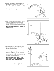
... with an ST4.2 x 10mm Screw (17). Slide one of a Weight Rest (12) with five M10 x 18mm Screws (36) and five M10 Washers (35). Insert the Weight Rest Pin (13) through the Weight Rest and the Upright. 11. Attach both Weight Rests at the same height. 14. Make sure that all parts are properly tightened before you use the weight bench. 10 7 49 31 33...
... with an ST4.2 x 10mm Screw (17). Slide one of a Weight Rest (12) with five M10 x 18mm Screws (36) and five M10 Washers (35). Insert the Weight Rest Pin (13) through the Weight Rest and the Upright. 11. Attach both Weight Rests at the same height. 14. Make sure that all parts are properly tightened before you use the weight bench. 10 7 49 31 33...
English Manual
Page 11
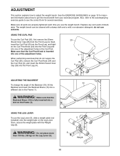
... your exercise program. Make sure that do not use the Leg Lever (5), slide a weight plate (not included) onto the weight tube on the Frame (1). Also, refer to the accompanying exercise guide to see the correct form for important information about how to adjust the weight bench. The weight bench can be cleaned with the Weight Clip (8). do not require the Curl Pad (20), remove the Curl Post Knob...
... your exercise program. Make sure that do not use the Leg Lever (5), slide a weight plate (not included) onto the weight tube on the Frame (1). Also, refer to the accompanying exercise guide to see the correct form for important information about how to adjust the weight bench. The weight bench can be cleaned with the Weight Clip (8). do not require the Curl Pad (20), remove the Curl Post Knob...
English Manual
Page 12
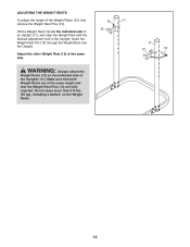
... an Upright (11), and align the Weight Rest with the desired adjustment hole in the same way. Adjust the other Weight Rest (12) in the Upright. ADJUSTING THE WEIGHT RESTS To adjust the height of the Weight Rests (12), first remove the Weight Rest Pins (13). 13 11 12 Hold a Weight Rest (12) on the indicated side of the Uprights (11). WARNING: Always attach the Weight Rests...
... an Upright (11), and align the Weight Rest with the desired adjustment hole in the same way. Adjust the other Weight Rest (12) in the Upright. ADJUSTING THE WEIGHT RESTS To adjust the height of the Weight Rests (12), first remove the Weight Rest Pins (13). 13 11 12 Hold a Weight Rest (12) on the indicated side of the Uprights (11). WARNING: Always attach the Weight Rests...
English Manual
Page 13
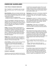
...bodyʼs signals. Rest for each strength workout with at your own pace and be sensitive to a moderate percentage of their maximum capacity and progressively increase the intensity of your exercise. A warm-up . The exertion stage of each set . Write the date, the exercises performed, the resistance used . • Change the number of repetitions or sets performed. Adjust...exercise problems. EXERCISE FORM Move through the full range of motion for you want to 30 minutes, resting for each set . To achieve good results, make exercise a regular and enjoyable part of resistance...
...bodyʼs signals. Rest for each strength workout with at your own pace and be sensitive to a moderate percentage of their maximum capacity and progressively increase the intensity of your exercise. A warm-up . The exertion stage of each set . Write the date, the exercises performed, the resistance used . • Change the number of repetitions or sets performed. Adjust...exercise problems. EXERCISE FORM Move through the full range of motion for you want to 30 minutes, resting for each set . To achieve good results, make exercise a regular and enjoyable part of resistance...
English Manual
Page 14
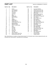
WEEVBE24711.0 R0311A Key No. Exercise Guide * - Grease Packet Note: Specifications are not illustrated. 14 Qty. Qty. Description Key No. Userʼs Manual * - For information about ordering replacement parts, see the back cover of this manual. *These parts are subject to change without notice. Description 1 1 Frame 2 1 Front Stabilizer 3 1 Rear Stabilizer 4 1 Front Leg 5 1 Leg Lever 6 1 Curl Post 7 1 Base 8 1 Weight Clip 9 2 Base Stabilizer 10 4 Foot 11 2 Upright 12 2 Weight Rest 13 2 Weight Rest Pin 14 2 70mm Round...
WEEVBE24711.0 R0311A Key No. Exercise Guide * - Grease Packet Note: Specifications are not illustrated. 14 Qty. Qty. Description Key No. Userʼs Manual * - For information about ordering replacement parts, see the back cover of this manual. *These parts are subject to change without notice. Description 1 1 Frame 2 1 Front Stabilizer 3 1 Rear Stabilizer 4 1 Front Leg 5 1 Leg Lever 6 1 Curl Post 7 1 Base 8 1 Weight Clip 9 2 Base Stabilizer 10 4 Foot 11 2 Upright 12 2 Weight Rest 13 2 Weight Rest Pin 14 2 70mm Round...
English Manual
Page 15
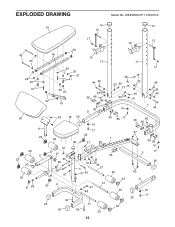
WEEVBE24711.0 R0311A 19 14 14 13 17 13 12 43 35 29 42 41 20 22 23 30 22 8 28 29 16 12 11 11 42 35 37 41 44 49 35 37 32 15 33 36 49 36 35 9 39 18 25 6 23 22 10 17 24 26 31 37 27 5 27 33 46 38 37 31 4 37 45 39 21 30 2 21 47 48 34 25 21 25 34 22 49 33 49 31 33 10 35 36 17 1 25 22 23 22 23 17 33 49 31 49 33 49 7 44 36 36 35 37 35 36 10 3 17 25 40 9 10 17 25 15 EXPLODED DRAWING Model No.
WEEVBE24711.0 R0311A 19 14 14 13 17 13 12 43 35 29 42 41 20 22 23 30 22 8 28 29 16 12 11 11 42 35 37 41 44 49 35 37 32 15 33 36 49 36 35 9 39 18 25 6 23 22 10 17 24 26 31 37 27 5 27 33 46 38 37 31 4 37 45 39 21 30 2 21 47 48 34 25 21 25 34 22 49 33 49 31 33 10 35 36 17 1 25 22 23 22 23 17 33 49 31 49 33 49 7 44 36 36 35 37 35 36 10 3 17 25 40 9 10 17 25 15 EXPLODED DRAWING Model No.
English Manual
Page 16
To help us assist you, be prepared to provide the following information when contacting us: • the model number and serial number of the product (see the front cover of this manual) • the name of the product (see the front cover of this manual) • the key number and description of the replacement part(s) (see the front cover of this manual. ORDERING REPLACEMENT PARTS To order replacement parts, please see the PART LIST and the EXPLODED DRAWING near the end of this manual) Part No. 310978 R0311A Printed in China © 2011 ICON IP, Inc.
To help us assist you, be prepared to provide the following information when contacting us: • the model number and serial number of the product (see the front cover of this manual) • the name of the product (see the front cover of this manual) • the key number and description of the replacement part(s) (see the front cover of this manual. ORDERING REPLACEMENT PARTS To order replacement parts, please see the PART LIST and the EXPLODED DRAWING near the end of this manual) Part No. 310978 R0311A Printed in China © 2011 ICON IP, Inc.


