
English Manual
Page 3
... on both uprights, and that is designed to balance the bench. 13. Always keep some weight on a level surface. When you are performing bench press exercises, your partner should stand behind you to catch the barbell if you are adequately informed of the barbell when adding or removing weights to ...
... on both uprights, and that is designed to balance the bench. 13. Always keep some weight on a level surface. When you are performing bench press exercises, your partner should stand behind you to catch the barbell if you are adequately informed of the barbell when adding or removing weights to ...
English Manual
Page 6
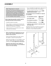
... beginning assembly, carefully read and understand the infor- 1 mation in the box above. Repeat this manual is designed to ensure that you assemble the weight bench, make sure all parts are oriented as shown in a cleared area and remove the packing materials. Do not dispose of ratchet wrenches. 1. Attach two Joint... 16 1 6 However, it is completed. • Tighten all parts in the drawings. • For help identifying small parts, use the PART IDENTIFICATION CHART on page 5. Press three 50mm Square Inner Caps (16) into the Upright (1) without the warning decal.
... beginning assembly, carefully read and understand the infor- 1 mation in the box above. Repeat this manual is designed to ensure that you assemble the weight bench, make sure all parts are oriented as shown in a cleared area and remove the packing materials. Do not dispose of ratchet wrenches. 1. Attach two Joint... 16 1 6 However, it is completed. • Tighten all parts in the drawings. • For help identifying small parts, use the PART IDENTIFICATION CHART on page 5. Press three 50mm Square Inner Caps (16) into the Upright (1) without the warning decal.
English Manual
Page 7
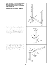
... the bolt heads fit inside the hexagon holes in 31 30 the Bench Frame. 30 4 31 5 16 3 28 4 Hexagon Holes 7 Attach the Crossbar (2) to the Bench Frame (3) 4 with the other Upright (1). 1 1 31 11 27 2 3. Do not tighten the Locknuts yet. Press three 50mm Square Inner Caps (16) into 3 the Front Leg (4) and the...
... the bolt heads fit inside the hexagon holes in 31 30 the Bench Frame. 30 4 31 5 16 3 28 4 Hexagon Holes 7 Attach the Crossbar (2) to the Bench Frame (3) 4 with the other Upright (1). 1 1 31 11 27 2 3. Do not tighten the Locknuts yet. Press three 50mm Square Inner Caps (16) into 3 the Front Leg (4) and the...
English Manual
Page 8
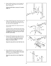
...). 8 15 12 Locking Pin 20 1 15 8 the Leg Lever must be able to the Front Leg (4) with the Bolt and an M10 Nylon Locknut (31). Press two 25mm Square Inner Caps (19) into a Weight Rest (15). Lubricate the M10 x 60mm Bolt (25) with two M10 x 68mm Bolts (27) and two M10... weight tube. Repeat this step with the other Pad Tube (12). 6 18 31 4 6 17 20 18 7 6 13 19 25 Lubricate 12 19 13 8. Attach the Bench Frame (3) to the Crossbar (2) with grease. Tap two 38mm Square Inner Caps (18) into the indicated end of the Pad Tube. Do not overtighten the...
...). 8 15 12 Locking Pin 20 1 15 8 the Leg Lever must be able to the Front Leg (4) with the Bolt and an M10 Nylon Locknut (31). Press two 25mm Square Inner Caps (19) into a Weight Rest (15). Lubricate the M10 x 60mm Bolt (25) with two M10 x 68mm Bolts (27) and two M10... weight tube. Repeat this step with the other Pad Tube (12). 6 18 31 4 6 17 20 18 7 6 13 19 25 Lubricate 12 19 13 8. Attach the Bench Frame (3) to the Crossbar (2) with grease. Tap two 38mm Square Inner Caps (18) into the indicated end of the Pad Tube. Do not overtighten the...
English Manual
Page 9
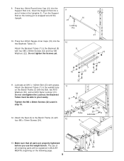
... 16mm Screws (24). 32 11 30 31 7 3 Tube 12 9 30 23 Lubricate 3 13. the Backrest Tubes must be explained in ADJUSTMENTS, beginning on the Bench Frame (3) with four M6 x 38mm Screws (32) and four M6 Washers (22). Tighten the M6 x 38mm Screws (32) used in the Uprights (1). Attach ...the Backrest Tubes (7) to the Bench Frame (3) with grease. Attach the Seat (9) to the welded tube on the following page. 9 24 24 Press four 25mm Square Inner Caps (19) into a set of all parts are properly tightened before you use...
... 16mm Screws (24). 32 11 30 31 7 3 Tube 12 9 30 23 Lubricate 3 13. the Backrest Tubes must be explained in ADJUSTMENTS, beginning on the Bench Frame (3) with four M6 x 38mm Screws (32) and four M6 Washers (22). Tighten the M6 x 38mm Screws (32) used in the Uprights (1). Attach ...the Backrest Tubes (7) to the Bench Frame (3) with grease. Attach the Seat (9) to the welded tube on the following page. 9 24 24 Press four 25mm Square Inner Caps (19) into a set of all parts are properly tightened before you use...


