
English Manual
Page 7
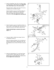
Press the 51mm x 76mm Inner Cap (14) into 4 the Backrest Frame (6). Attach the Backrest Bracket (16) to the Bench Base (3) with four M10 x 71mm Bolts (31), two Bench Base Joint Plates (25), and four M10 Nylon Locknuts (34). Do not tighten the Locknuts yet. 7 30 35 35 7 17 34 34 ... Locknuts (34). 30 35 35 15 6 15 16 34 5. Press two 38mm x 50mm Inner Caps (15) into the indicated end of the Bench Leg (4). 4 Attach the Bench Leg (4) to the Backrest Frame (6) with four M10 x 94mm Bolts (98), two Bench Joint Plates (24), and four M10 Nylon Locknuts (34). Attach ...
Press the 51mm x 76mm Inner Cap (14) into 4 the Backrest Frame (6). Attach the Backrest Bracket (16) to the Bench Base (3) with four M10 x 71mm Bolts (31), two Bench Base Joint Plates (25), and four M10 Nylon Locknuts (34). Do not tighten the Locknuts yet. 7 30 35 35 7 17 34 34 ... Locknuts (34). 30 35 35 15 6 15 16 34 5. Press two 38mm x 50mm Inner Caps (15) into the indicated end of the Bench Leg (4). 4 Attach the Bench Leg (4) to the Backrest Frame (6) with four M10 x 94mm Bolts (98), two Bench Joint Plates (24), and four M10 Nylon Locknuts (34). Attach ...

English Manual
Page 8
...102) to the Bench Frame (1) with the Bolt, two M10 Washers (35), and an M10 Nylon Locknut (34). Pull out the Small Adjustment Knob (23) by turning it counterclockwise several turns. Attach the Seat Frame (7) and the Backrest Frame (6) to the round hole in the Bracket. Press three 50mm Square...Attach the Seat (10) to the Backrest Frame (6) with an M10 Nylon Locknut (34). 6. Insert the Backrest Bracket (16) between the tubes on the Bench Frame (1) and engage the Small Adjustment Knob into the Seat Frame (7). Lubricate the M10 x 102mm Bolt (99) with grease. Pull the Knob out and...
...102) to the Bench Frame (1) with the Bolt, two M10 Washers (35), and an M10 Nylon Locknut (34). Pull out the Small Adjustment Knob (23) by turning it counterclockwise several turns. Attach the Seat Frame (7) and the Backrest Frame (6) to the round hole in the Bracket. Press three 50mm Square...Attach the Seat (10) to the Backrest Frame (6) with an M10 Nylon Locknut (34). 6. Insert the Backrest Bracket (16) between the tubes on the Bench Frame (1) and engage the Small Adjustment Knob into the Seat Frame (7). Lubricate the M10 x 102mm Bolt (99) with grease. Pull the Knob out and...

English Manual
Page 9
... 9 10. Slide the Pad Tube into a hole in the same manner. 10 5 27 26 28 27 11. Press two 25mm Square Inner Caps (28) into the bottom of the Left Base in the same manner. Press a 45mm Square Inner Cap (12) into a Pad Tube (27). Attach another Large Base Cap to the...
... 9 10. Slide the Pad Tube into a hole in the same manner. 10 5 27 26 28 27 11. Press two 25mm Square Inner Caps (28) into the bottom of the Left Base in the same manner. Press a 45mm Square Inner Cap (12) into a Pad Tube (27). Attach another Large Base Cap to the...

English Manual
Page 10
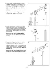
... (44) face the holes on the Rear Upright (43), and that the numbers on the Left Front Upright face the numbers on the side shown. Press a 60mm Square Inner Cap (64) into the top of the Left Front Upright (44). Make sure the holes are shorter than the Front Uprights (not...
... (44) face the holes on the Rear Upright (43), and that the numbers on the Left Front Upright face the numbers on the side shown. Press a 60mm Square Inner Cap (64) into the top of the Left Front Upright (44). Make sure the holes are shorter than the Front Uprights (not...
English Manual
Page 11
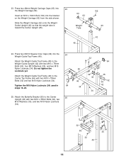
... tighten the Locknuts yet. 47 Repeat this step with the Left Weight Rest 22 (not shown) and the Left Front Upright (not shown). 110 17. Press a 60mm Square Inner Cap (64) into a set of the Right Top Frame (47). 64 Attach the Right Top Frame (47) to the right Rear Upright...
... tighten the Locknuts yet. 47 Repeat this step with the Left Weight Rest 22 (not shown) and the Left Front Upright (not shown). 110 17. Press a 60mm Square Inner Cap (64) into a set of the Right Top Frame (47). 64 Attach the Right Top Frame (47) to the right Rear Upright...

English Manual
Page 13
.... Attach the Weight Guide Upright (42) to the Center Base (39) with two M10 x 81mm Button Bolts (104) and two M10 Nylon Locknuts (34). 20. Press a 60mm Square Inner Cap (64) into the Weight Guide Base (41). Attach the Foot Plate (67) and the Weight Guide Base (41) to the Weight...
.... Attach the Weight Guide Upright (42) to the Center Base (39) with two M10 x 81mm Button Bolts (104) and two M10 Nylon Locknuts (34). 20. Press a 60mm Square Inner Cap (64) into the Weight Guide Base (41). Attach the Foot Plate (67) and the Weight Guide Base (41) to the Weight...
English Manual
Page 14
Press two 60mm Square Inner Caps (64) into 23 the Weight Carriage (62). Attach the Weight Guide Top Frame (49) to the Center Top Frame (46) ... Butterfly Bracket (55) to the Weight Guide Upright (42) with two M10 x 75mm Bolts (92), four M10 Washers (35), and two M10 Nylon Locknuts (34). Press two 48mm Weight Carriage Caps (63) into the 24 Weight Guide Top Frame (49). Do not tighten the Locknuts yet. Tighten the M10 Nylon Locknuts...
Press two 60mm Square Inner Caps (64) into 23 the Weight Carriage (62). Attach the Weight Guide Top Frame (49) to the Center Top Frame (46) ... Butterfly Bracket (55) to the Weight Guide Upright (42) with two M10 x 75mm Bolts (92), four M10 Washers (35), and two M10 Nylon Locknuts (34). Press two 48mm Weight Carriage Caps (63) into the 24 Weight Guide Top Frame (49). Do not tighten the Locknuts yet. Tighten the M10 Nylon Locknuts...

English Manual
Page 15
...) in the indicated location. Repeat this step with grease. Attach the Dip Arm (60) to pivot easily. Press two Plastic Butterfly Bushings (79) and two Metal Butterfly Bushings (113) into the Right Butterfly Arm (56). Attach...two M6 Washers (78) and two M6 x 75mm Screws (96). 51 28 96 78 45 96 78 112 15 Press two Caps w/Holes (61) and two Handgrips (59) onto the Dip Arm (60). Attach the Butterfly Backrest (112... 94 57 56 Lubricate 80 13 66 27 101 34 34 Warning Decal 60 61 59 61 59 28. Press a 50mm Square Inner Cap (13) and a 25mm Square Inner Cap (28) into the Arm. Cover ...
...) in the indicated location. Repeat this step with grease. Attach the Dip Arm (60) to pivot easily. Press two Plastic Butterfly Bushings (79) and two Metal Butterfly Bushings (113) into the Right Butterfly Arm (56). Attach...two M6 Washers (78) and two M6 x 75mm Screws (96). 51 28 96 78 45 96 78 112 15 Press two Caps w/Holes (61) and two Handgrips (59) onto the Dip Arm (60). Attach the Butterfly Backrest (112... 94 57 56 Lubricate 80 13 66 27 101 34 34 Warning Decal 60 61 59 61 59 28. Press a 50mm Square Inner Cap (13) and a 25mm Square Inner Cap (28) into the Arm. Cover ...


