
English Manual
Page 1
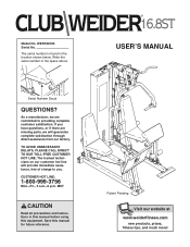
... DELAYS, PLEASE CALL DIRECT TO OUR TOLL-FREE CUSTOMER HOT LINE. USERÕS MANUAL Patent Pending Visit our website at www.weiderfitness.com new products, prizes, fitness tips, and much more! Serial Number Decal QUESTIONS? As a manufacturer, we are missing parts, we will provide immediate assistance, free of charge to providing complete customer satisfaction. The trained technicians on our customer...
... DELAYS, PLEASE CALL DIRECT TO OUR TOLL-FREE CUSTOMER HOT LINE. USERÕS MANUAL Patent Pending Visit our website at www.weiderfitness.com new products, prizes, fitness tips, and much more! Serial Number Decal QUESTIONS? As a manufacturer, we are missing parts, we will provide immediate assistance, free of charge to providing complete customer satisfaction. The trained technicians on our customer...
English Manual
Page 2
... purchase. Before shipping, always obtain a Return Authorization Number (RA No.) from the original purchaser. Table of Contents Limited Warranty 2 Important Precautions 3 Before You Begin 4 Assembly 5 Cable Diagram 21 Adjustment 22 Trouble-shooting and Maintenance 24 Weight Resistance Chart 25 Ordering Replacement Parts Back Cover Note: A PART LIST/EXPLODED DRAWING and a PART IDENTIFICATION CHART are performed by an ICON trained and authorized service provider, or, at 1-800-999-3756 and tell them your...
... purchase. Before shipping, always obtain a Return Authorization Number (RA No.) from the original purchaser. Table of Contents Limited Warranty 2 Important Precautions 3 Before You Begin 4 Assembly 5 Cable Diagram 21 Adjustment 22 Trouble-shooting and Maintenance 24 Weight Resistance Chart 25 Ordering Replacement Parts Back Cover Note: A PART LIST/EXPLODED DRAWING and a PART IDENTIFICATION CHART are performed by an ICON trained and authorized service provider, or, at 1-800-999-3756 and tell them your...
English Manual
Page 3
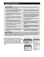
... one person at all times. Never release the press arm, leg lever, lat bar, leg press, ab strap, or ankle strap while weights are exercising, stop immediately and begin cooling down. 4. ICON assumes no responsibility for persons over the age of this or any worn parts immediately. 6. The warning decals shown at all users of the training system are on the foot plate when perform- 14...
... one person at all times. Never release the press arm, leg lever, lat bar, leg press, ab strap, or ankle strap while weights are exercising, stop immediately and begin cooling down. 4. ICON assumes no responsibility for persons over the age of this or any worn parts immediately. 6. The warning decals shown at all users of the training system are on the foot plate when perform- 14...
English Manual
Page 4
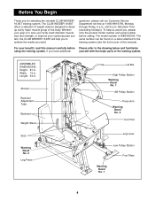
... versatile CLUB WEIDER¨ 16.8ST training system. questions, please call our Customer Service Department toll-free at 1-800-999-3756, Monday through Friday, 6 a.m. ASSEMBLED DIMENSIONS: Height: 81 in . Before You Begin Thank you have additional yourself with the major parts of the training system. until 6 p.m. Shroud Backrest Adjustment Tube Backrest Weight Stack Seat Warning Decal No. 2 Leg Press Lat Bar High Pulley Station Warning Decal No. 1 AB Pulley Station Press Arm...
... versatile CLUB WEIDER¨ 16.8ST training system. questions, please call our Customer Service Department toll-free at 1-800-999-3756, Monday through Friday, 6 a.m. ASSEMBLED DIMENSIONS: Height: 81 in . Before You Begin Thank you have additional yourself with the major parts of the training system. until 6 p.m. Shroud Backrest Adjustment Tube Backrest Weight Stack Seat Warning Decal No. 2 Leg Press Lat Bar High Pulley Station Warning Decal No. 1 AB Pulley Station Press Arm...

English Manual
Page 5
... base and the uprights that all parts are found in this stage you will assemble the seats, the backrests, the curl pad, the shroud, and other parts to Orient Parts As you will attach the cables and pulleys that connect the arms and other miscellaneous parts. 5 Note: Assembly will begin each stage to assemble the training system over a couple of the training system. How to the weights.
... base and the uprights that all parts are found in this stage you will assemble the seats, the backrests, the curl pad, the shroud, and other parts to Orient Parts As you will attach the cables and pulleys that connect the arms and other miscellaneous parts. 5 Note: Assembly will begin each stage to assemble the training system over a couple of the training system. How to the weights.
English Manual
Page 6
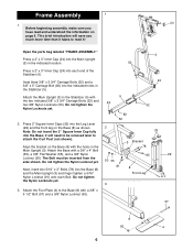
... introduction will need to attach the Curl Post (not shown). Open the parts bag labeled ÒFRAME ASSEMBLY.Ó Press a 2Ó x 3Ó Inner Cap (24) into the Leg Lever (29) and the front leg on page 5. Press 2Ó Square Inner Caps (33) into the Main Upright (3) in the Main Upright (3). Attach the Foot Plate (4) to the Stabilizer (5) with a 3/8Ó x 4Ó Bolt (65), a 3/8Ó...
... introduction will need to attach the Curl Post (not shown). Open the parts bag labeled ÒFRAME ASSEMBLY.Ó Press a 2Ó x 3Ó Inner Cap (24) into the Leg Lever (29) and the front leg on page 5. Press 2Ó Square Inner Caps (33) into the Main Upright (3) in the Main Upright (3). Attach the Foot Plate (4) to the Stabilizer (5) with a 3/8Ó x 4Ó Bolt (65), a 3/8Ó...
English Manual
Page 7
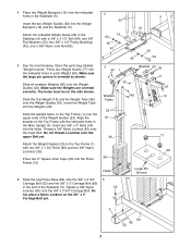
... (50). Open the parts bag labeled ÒWeight InsertsÓ. Insert the Weight Tube into the Weight Bumpers (19) and the Stabilizer (5). Press two Weight Inserts (77) into the indicated holes in the end of the Weight Guides (23). Slide the Top Weight (16) and the Weight Tube (36) onto the Weight Guides (23). Slide the Leg Press Base (84) onto the 3/8Ó x 3 3/4Ó 6 Carriage Bolt (52...
... (50). Open the parts bag labeled ÒWeight InsertsÓ. Insert the Weight Tube into the Weight Bumpers (19) and the Stabilizer (5). Press two Weight Inserts (77) into the indicated holes in the end of the Weight Guides (23). Slide the Top Weight (16) and the Weight Tube (36) onto the Weight Guides (23). Slide the Leg Press Base (84) onto the 3/8Ó x 3 3/4Ó 6 Carriage Bolt (52...

English Manual
Page 9
... easily. Attach the Press Arm (46) to the front leg of the adjustment holes in the Handle. Repeat for the other Handle. 9 11. Open the parts bags labeled ÒARM ASSEMBLYÓ. Release the Knob and let it snap into the indicated end of the Press Arm (46). Press a 2Ó Square Inner Cap (33) into one of the Adjustment Knobs (9) counterclockwise to the Sliding Seat Frame...
... easily. Attach the Press Arm (46) to the front leg of the adjustment holes in the Handle. Repeat for the other Handle. 9 11. Open the parts bags labeled ÒARM ASSEMBLYÓ. Release the Knob and let it snap into the indicated end of the Press Arm (46). Press a 2Ó Square Inner Cap (33) into one of the Adjustment Knobs (9) counterclockwise to the Sliding Seat Frame...
English Manual
Page 11
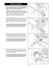
... Leg Press Base (84) with a 3/8Ó Nylon Locknut (50). Attach the Pulley and a Cable Trap (44) to the Rear Press Upright (97) with a 3/8Ó x 3Ó Bolt (45), two 3/8Ó Flat Washers (55), a 5/8Ó x 1/4Ó Bushing (90), and a 3/8Ó Nylon Jam Nut (63). 55 45 16. Wrap the Leg Press Cable (76) around a 4Ó Pulley 16 (35). Wrap the Leg Press Cable (76) up around a 4Ó Pulley (35). Attach the Pulley and a Cable...
... Leg Press Base (84) with a 3/8Ó Nylon Locknut (50). Attach the Pulley and a Cable Trap (44) to the Rear Press Upright (97) with a 3/8Ó x 3Ó Bolt (45), two 3/8Ó Flat Washers (55), a 5/8Ó x 1/4Ó Bushing (90), and a 3/8Ó Nylon Jam Nut (63). 55 45 16. Wrap the Leg Press Cable (76) around a 4Ó Pulley 16 (35). Wrap the Leg Press Cable (76) up around a 4Ó Pulley (35). Attach the Pulley and a Cable...
English Manual
Page 12
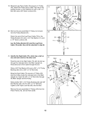
.... Tighten a 3/8Ó Nylon Jam Nut (63) onto the Bolt. 3 55 63 50 42 Remove the pre-assembled 4Ó Pulleys (35) from the Pulley Bracket (91). 20 Attach the end of the Leg Press Cable (76) to the 19 welded bracket on the other end. 21 Feed the end of the Cable through the indicated slot in the Main Upright (3). Attach the Pulley and a Cable Trap...
.... Tighten a 3/8Ó Nylon Jam Nut (63) onto the Bolt. 3 55 63 50 42 Remove the pre-assembled 4Ó Pulleys (35) from the Pulley Bracket (91). 20 Attach the end of the Leg Press Cable (76) to the 19 welded bracket on the other end. 21 Feed the end of the Cable through the indicated slot in the Main Upright (3). Attach the Pulley and a Cable Trap...

English Manual
Page 18
... Upright (3). Seat Assembly 38 38. Attach the Backrest (41) to loosen it snap into the seat frame on the Backrest Frame (15). Tighten the Knob fully. 34 30 40 Backrest Tube 43 Pad Bar 3 15 9 Adjustment Holes 18 Open the parts bag labeled ÒARM AND SEAT ASSEMBLY.Ó Attach a Seat (13) to loosen it. Press a 3/4Ó Round Inner Cap (34) into one of the pad bar. Turn the Knob...
... Upright (3). Seat Assembly 38 38. Attach the Backrest (41) to loosen it snap into the seat frame on the Backrest Frame (15). Tighten the Knob fully. 34 30 40 Backrest Tube 43 Pad Bar 3 15 9 Adjustment Holes 18 Open the parts bag labeled ÒARM AND SEAT ASSEMBLY.Ó Attach a Seat (13) to loosen it. Press a 3/4Ó Round Inner Cap (34) into one of the pad bar. Turn the Knob...

English Manual
Page 20
...Bolts must be explained in ADJUSTMENT, beginning on the Top Frame (1) with four #8 x 3/4Ó Screws (32). The Screws must be damaged when heavy weight is lined up with 48 four 1/4Ó x 3/4Ó Bolts (17). 49. Insert a 1Ó Round Inner Cap (103) into the Tinnerman Clips (38). Attach the lower end of the Lat Bar... Make sure that the cables move smoothly, find and correct the problem. 21 83 IMPORTANT: If the cables are not properly installed, they may be inserted through the square holes in the Shroud. The use of the remaining parts will need to the Curl Post (...
...Bolts must be explained in ADJUSTMENT, beginning on the Top Frame (1) with four #8 x 3/4Ó Screws (32). The Screws must be damaged when heavy weight is lined up with 48 four 1/4Ó x 3/4Ó Bolts (17). 49. Insert a 1Ó Round Inner Cap (103) into the Tinnerman Clips (38). Attach the lower end of the Lat Bar... Make sure that the cables move smoothly, find and correct the problem. 21 83 IMPORTANT: If the cables are not properly installed, they may be inserted through the square holes in the Shroud. The use of the remaining parts will need to the Curl Post (...
English Manual
Page 22
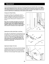
... desired position. Attaching the Lat Bar, Ankle Strap, or Ab Strap The Lat Bar (61), Ankle Strap (10), and Ab Strap (75) can be set up for each exercise. Be sure to insert the Weight Pin until the ball is in the correct starting position for the exercise to be reduced. Adjustment The instructions below describe how each part of the training system can be performed. Adjust the length of...
... desired position. Attaching the Lat Bar, Ankle Strap, or Ab Strap The Lat Bar (61), Ankle Strap (10), and Ab Strap (75) can be set up for each exercise. Be sure to insert the Weight Pin until the ball is in the correct starting position for the exercise to be reduced. Adjustment The instructions below describe how each part of the training system can be performed. Adjust the length of...
English Manual
Page 23
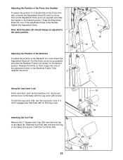
... the Pad Tube (28) on the Leg Lever. Adjusting the Position of the Press Arm Handles To adjust the position of a Handle (20) on the Press Arm (46), unscrew the Adjustment Knob (9) until it is loose. Snap the Adjustment Knob into one of the adjustment holes in the Handle. Release the Knob so that it with the Leg Lever (29) locked. Slide the Curl...
... the Pad Tube (28) on the Leg Lever. Adjusting the Position of the Press Arm Handles To adjust the position of a Handle (20) on the Press Arm (46), unscrew the Adjustment Knob (9) until it is loose. Snap the Adjustment Knob into one of the adjustment holes in the Handle. Release the Knob so that it with the Leg Lever (29) locked. Slide the Curl...
English Manual
Page 24
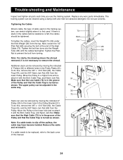
... High Cable (73). The training system can be removed by moving the indicated 4Ó Pulleys (35) to slip off the pulleys, the cable may have become twisted. Remove the cable and re-install it is felt, the cables should be cleaned using a damp cloth and mild non-abrasive detergent. Bolt To tighten the cables, insert the Weight Pin (39) under 36 the third Weight (26) from turning. Replace any worn parts immediately...
... High Cable (73). The training system can be removed by moving the indicated 4Ó Pulleys (35) to slip off the pulleys, the cable may have become twisted. Remove the cable and re-install it is felt, the cables should be cleaned using a damp cloth and mild non-abrasive detergent. Bolt To tighten the cables, insert the Weight Pin (39) under 36 the third Weight (26) from turning. Replace any worn parts immediately...
English Manual
Page 25
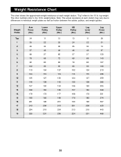
... 14 15 16 17 18 19 Arm Press (lbs.) 24 35 46 57 68 79 90 102 113 124 135 146 157 168 179 190 201 213 224 235 Lower Pulley (lbs.) 11 22 34 46 57 69 80 92 104 115 127 138 150 162 173 185 196 208 219 231 Upper Pulley (lbs.) 13... Leg Press (lbs.) 28 51 74 97 120 143 167 190 213 236 259 282 305 328 351 374 397 420 443 466 25 Note: The actual resistance at each station may vary due to differences in individual weight plates as well as friction between the cables, pulleys, and weight guides. The other numbers refer to the 10 lb. Weight Resistance Chart...
... 14 15 16 17 18 19 Arm Press (lbs.) 24 35 46 57 68 79 90 102 113 124 135 146 157 168 179 190 201 213 224 235 Lower Pulley (lbs.) 11 22 34 46 57 69 80 92 104 115 127 138 150 162 173 185 196 208 219 231 Upper Pulley (lbs.) 13... Leg Press (lbs.) 28 51 74 97 120 143 167 190 213 236 259 282 305 328 351 374 397 420 443 466 25 Note: The actual resistance at each station may vary due to differences in individual weight plates as well as friction between the cables, pulleys, and weight guides. The other numbers refer to the 10 lb. Weight Resistance Chart...
English Manual
Page 26
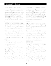
... their capacity. This requires moving only the appropriate parts of the muscles. On the exercise poster accompanying this manual, you . When you feeling exhausted. Work your limits and select the amount of 15 to develop the most. Weight Loss To lose weight, use a low amount of resistance and increase the number of repetitions in two ways: ¥ by changing the amount of resistance used ¥...
... their capacity. This requires moving only the appropriate parts of the muscles. On the exercise poster accompanying this manual, you . When you feeling exhausted. Work your limits and select the amount of 15 to develop the most. Weight Loss To lose weight, use a low amount of resistance and increase the number of repetitions in two ways: ¥ by changing the amount of resistance used ¥...
English Manual
Page 27
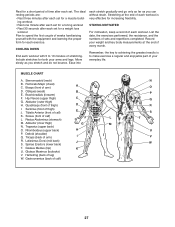
... seconds after each set. COOLING DOWN End each workout. List the date, the exercises performed, the resistance, and the numbers of arm) D. Remember, the key to achieving the greatest results is very effective for increasing flexibility. Biceps (front of sets and repetitions completed. Soleus (front of thigh) J. Deltoid (shoulder) Q. Latissimus Dorsi (mid back) J S. Gluteus Medius (hip) K U. Move slowly as you...
... seconds after each set. COOLING DOWN End each workout. List the date, the exercises performed, the resistance, and the numbers of arm) D. Remember, the key to achieving the greatest results is very effective for increasing flexibility. Biceps (front of sets and repetitions completed. Soleus (front of thigh) J. Deltoid (shoulder) Q. Latissimus Dorsi (mid back) J S. Gluteus Medius (hip) K U. Move slowly as you...
English Manual
Page 31
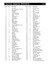
... Bolt Curl Post Leg Press Base Leg Press Plate Hand Grip 3/8Ó x 3 1/4Ó Bolt Seat Frame Channel Curl Knob 5/8Ó x 1/4Ó Bushing Pulley Bracket 3/8Ó x 3 3/4Ó Bolt Tab 1/2Ó x 1 3/4Ó Bushing 1/4Ó x 1Ó Bolt 5/16Ó x 2 1/2Ó Bolt Rear Leg Press Upright Forward Leg Press Upright Angle Cap Leg Press Attachment 1/4Ó x 1 1/2Ó Bolt Chart Decal 1Ó Round Inner Cap Large Washer Handle 1/2Ó x 3/4Ó Long Bushing 3/8Ó x 3Ó Carriage Bolt UserÕs Manual (not illustrated) WESY69100 R1000A Key...
... Bolt Curl Post Leg Press Base Leg Press Plate Hand Grip 3/8Ó x 3 1/4Ó Bolt Seat Frame Channel Curl Knob 5/8Ó x 1/4Ó Bushing Pulley Bracket 3/8Ó x 3 3/4Ó Bolt Tab 1/2Ó x 1 3/4Ó Bushing 1/4Ó x 1Ó Bolt 5/16Ó x 2 1/2Ó Bolt Rear Leg Press Upright Forward Leg Press Upright Angle Cap Leg Press Attachment 1/4Ó x 1 1/2Ó Bolt Chart Decal 1Ó Round Inner Cap Large Washer Handle 1/2Ó x 3/4Ó Long Bushing 3/8Ó x 3Ó Carriage Bolt UserÕs Manual (not illustrated) WESY69100 R1000A Key...
English Manual
Page 33
... this manual) ¥ The KEY NUMBER and DESCRIPTION of the part(s) (see the PART LIST and EXPLODED DRAWING attached in Canada © 2000 ICON Health & Fitness, Inc. Ordering Replacement Parts To order replacement parts, simply call our Customer Service Department toll-free at 1-800-999-3756, Monday through Friday, 6 a.m. until 6 p.m. Mountain Time (excluding holidays). To help us assist you, please be prepared to give the following information...
... this manual) ¥ The KEY NUMBER and DESCRIPTION of the part(s) (see the PART LIST and EXPLODED DRAWING attached in Canada © 2000 ICON Health & Fitness, Inc. Ordering Replacement Parts To order replacement parts, simply call our Customer Service Department toll-free at 1-800-999-3756, Monday through Friday, 6 a.m. until 6 p.m. Mountain Time (excluding holidays). To help us assist you, please be prepared to give the following information...


