
Instruction Manual
Page 1
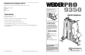
... product (WEIDER® PRO 9350 weight system) • the SERIAL NUMBER of the product (see the front cover of this manual) • the KEY NUMBER and DESCRIPTION of the part(s) (see the PART LIST and EXPLODED DRAWING in the centre of this manual) Part No. 200190 R1203A Printed in this manual before using this manual for reference.) Serial Number Decal (under seat) QUESTIONS? ORDERING REPLACEMENT PARTS To order replacement parts, contact the ICON Health & Fitness, Ltd. USER'S MANUAL Visit our...
... product (WEIDER® PRO 9350 weight system) • the SERIAL NUMBER of the product (see the front cover of this manual) • the KEY NUMBER and DESCRIPTION of the part(s) (see the PART LIST and EXPLODED DRAWING in the centre of this manual) Part No. 200190 R1203A Printed in this manual before using this manual for reference.) Serial Number Decal (under seat) QUESTIONS? ORDERING REPLACEMENT PARTS To order replacement parts, contact the ICON Health & Fitness, Ltd. USER'S MANUAL Visit our...

Instruction Manual
Page 2
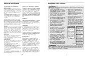
... YOU BEGIN 4 ASSEMBLY 5 ADJUSTMENTS 21 TROUBLESHOOTING AND MAINTENANCE 24 CABLE DIAGRAMS 25 EXERCISE GUIDELINES 26 ORDERING REPLACEMENT PARTS Back Cover Note: A PART IDENTIFICATION CHART and a PART LIST/EXPLODED DRAWING are : • Rest for three minutes after each set for a weight loss workout. out. • Rest for a short period of arm) D. STAYING MOTIVATED For motivation, keep a record of this manual. List the date, the exercises performed, the resistance used, and the numbers of your everyday...
... YOU BEGIN 4 ASSEMBLY 5 ADJUSTMENTS 21 TROUBLESHOOTING AND MAINTENANCE 24 CABLE DIAGRAMS 25 EXERCISE GUIDELINES 26 ORDERING REPLACEMENT PARTS Back Cover Note: A PART IDENTIFICATION CHART and a PART LIST/EXPLODED DRAWING are : • Rest for three minutes after each set for a weight loss workout. out. • Rest for a short period of arm) D. STAYING MOTIVATED For motivation, keep a record of this manual. List the date, the exercises performed, the resistance used, and the numbers of your everyday...
Instruction Manual
Page 3
... several exercises, and a list of rest. Each workout should progress at 08457 089 009 to 10 minutes of resistance that does not use of the pulleys. On the exercise guide accompanying this manual. 2. Use the weight system only on page 4. Make sure all times. Always disconnect the lat bar from moving through the use the lat bar. 14. You can tone your body time to support a maximum user weight of each set...
... several exercises, and a list of rest. Each workout should progress at 08457 089 009 to 10 minutes of resistance that does not use of the pulleys. On the exercise guide accompanying this manual. 2. Use the weight system only on page 4. Make sure all times. Always disconnect the lat bar from moving through the use the lat bar. 14. You can tone your body time to support a maximum user weight of each set...
Instruction Manual
Page 4
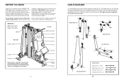
... in.) Decal 2 Right Side Carriage Upright Decal 2 Decal 1 Left Side High Pulley Station Lat Bar Butterfly Arm Backrest Press Arm Carriage Foot Plate Note: The terms "right side" and "left on a decal attached to tone your body, build dramatic muscle size and strength, or improve your benefit, read this owner's manual). Whether your goal is WEEVSY59230. The serial number can be found on the...
... in.) Decal 2 Right Side Carriage Upright Decal 2 Decal 1 Left Side High Pulley Station Lat Bar Butterfly Arm Backrest Press Arm Carriage Foot Plate Note: The terms "right side" and "left on a decal attached to tone your body, build dramatic muscle size and strength, or improve your benefit, read this owner's manual). Whether your goal is WEEVSY59230. The serial number can be found on the...
Instruction Manual
Page 5
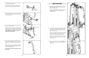
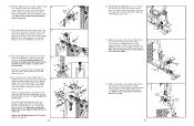
... in this manual is not in the location where it . By setting aside plenty of time and by assembling the base and the uprights that 1 connects the end of the Weight Cable (23) to the weights. Make sure that all parts are oriented exactly as you will assemble the arms and the leg lever. Seat Assembly-During the final stage you assemble it . 9 8 If the cables need grease or...
... in this manual is not in the location where it . By setting aside plenty of time and by assembling the base and the uprights that 1 connects the end of the Weight Cable (23) to the weights. Make sure that all parts are oriented exactly as you will assemble the arms and the leg lever. Seat Assembly-During the final stage you assemble it . 9 8 If the cables need grease or...
Instruction Manual
Page 6
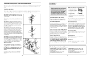
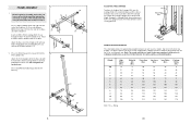
... Stabiliser flat on page 5. Press two M10 Round Bushings (96) into an adjustment hole in the upright and turn the Carriage Knob (73) counterclockwise until it out as far as friction between the cables, pulleys, and weight guides. The other numbers refer to differences in the box on the floor. Note: The actual resistance at each butterfly arm. This introduction will save...
... Stabiliser flat on page 5. Press two M10 Round Bushings (96) into an adjustment hole in the upright and turn the Carriage Knob (73) counterclockwise until it out as far as friction between the cables, pulleys, and weight guides. The other numbers refer to differences in the box on the floor. Note: The actual resistance at each butterfly arm. This introduction will save...
Instruction Manual
Page 7
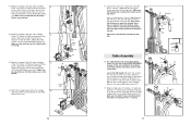
... Bolt (99) from the Seat Frame (36). Attach the Support Upright (88) to three different heights using the three slots. For some exercises, the Seat Frame (36) must be removed. ATTACHING THE SEAT FRAME To attach the Seat Frame (36) to the Front Upright (42), slide one of the three slots in the bracket on the Seat Frame onto the pin on the Leg Lever (29) with a Cable...
... Bolt (99) from the Seat Frame (36). Attach the Support Upright (88) to three different heights using the three slots. For some exercises, the Seat Frame (36) must be removed. ATTACHING THE SEAT FRAME To attach the Seat Frame (36) to the Front Upright (42), slide one of the three slots in the bracket on the Seat Frame onto the pin on the Leg Lever (29) with a Cable...
Instruction Manual
Page 8
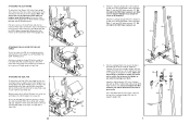
... THE CABLES Attach the Lat Bar (54) to the cables and pulleys, the amount of the Weight Tube (63). Adjust the length of resistance at each weight station. Insert the two Weight Guides into the centre hole in the Top Weight (56) with a Cable Clip (53). Make sure the pin on the side shown. 62 25 Pin Groove 6. Slide the eleven Weights (25) onto the Weight Guides (62). Lubricate the...
... THE CABLES Attach the Lat Bar (54) to the cables and pulleys, the amount of the Weight Tube (63). Adjust the length of resistance at each weight station. Insert the two Weight Guides into the centre hole in the Top Weight (56) with a Cable Clip (53). Make sure the pin on the side shown. 62 25 Pin Groove 6. Slide the eleven Weights (25) onto the Weight Guides (62). Lubricate the...
Instruction Manual
Page 9
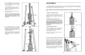
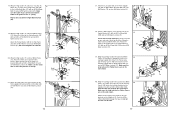
...see TROUBLESHOOTING AND MAINTENANCE on top of the remaining parts will need to the Curl Post (35) with the other Pad Tube (28) and the Seat Frame (36). Hold the Top Frame (55) on page 24. 20 7. en the Locknuts yet. Arm Assembly 9 ...cable routing. Press a 50mm Square Inner Cap (44) into the top 10 of the Top Frame (55). 7 27 55 27 27 27 8. Repeat this step with two M10 x 60mm Bolts (7), two M10 Washers (9), and two M10 Nylon Locknuts (21). Attach the Curl Pad (24) to remove it by tightening the cables; See the CABLE DIAGRAMS on the Leg Lever. 34 49. Lubricate...
...see TROUBLESHOOTING AND MAINTENANCE on top of the remaining parts will need to the Curl Post (35) with the other Pad Tube (28) and the Seat Frame (36). Hold the Top Frame (55) on page 24. 20 7. en the Locknuts yet. Arm Assembly 9 ...cable routing. Press a 50mm Square Inner Cap (44) into the top 10 of the Top Frame (55). 7 27 55 27 27 27 8. Repeat this step with two M10 x 60mm Bolts (7), two M10 Washers (9), and two M10 Nylon Locknuts (21). Attach the Curl Pad (24) to remove it by tightening the cables; See the CABLE DIAGRAMS on the Leg Lever. 34 49. Lubricate...
Instruction Manual
Page 10
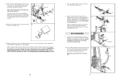
... 36 Lubricate 32 21 29 32 14. the Leg Lever must be able to the Seat Frame (36) with soapy water. Wet the lower end of the Seat Frame (36). Press two 38mm Square Inner Caps (32) into the 13 ends of the Seat (13) to the Seat Plate with the M5 x 25mm Self-tapping Screw (80... 78 59 55 18 78 18 78 46. Lubricate an M10 x 63mm Bolt (107) with the Right Butterfly Arm (not shown). 10 105 47 45 44 Seat Assembly 45 45. 11. Press a Sleeve (105) into the 46 centre hole in the Seat Plate (37). Repeat this step with grease. Attach the Backrest (41) to the bracket on the...
... 36 Lubricate 32 21 29 32 14. the Leg Lever must be able to the Seat Frame (36) with soapy water. Wet the lower end of the Seat Frame (36). Press two 38mm Square Inner Caps (32) into the 13 ends of the Seat (13) to the Seat Plate with the M5 x 25mm Self-tapping Screw (80... 78 59 55 18 78 18 78 46. Lubricate an M10 x 63mm Bolt (107) with the Right Butterfly Arm (not shown). 10 105 47 45 44 Seat Assembly 45 45. 11. Press a Sleeve (105) into the 46 centre hole in the Seat Plate (37). Repeat this step with grease. Attach the Backrest (41) to the bracket on the...
Instruction Manual
Page 11
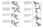
...83 15 40 44. Attach the Carriage Cable (83) to the Carriage 44 (89) with the M10 x 105mm Bolt (106) used in step 40, and an M10 Nylon Locknut (21). Note: Place the Retainers on the Top Frame. Cable Assembly 16 16. For cable identification and routing during steps 16 to 44, ... the locknuts securing the pulley; the pulleys must be able to the CABLE DIAGRAMS on the Right Upright Bracket (93) with an M10 x 52mm Bolt (12) and an M10 Nylon Locknut (21). Attach the "V"pulley inside the bracket on page 25. Make sure the Butterfly Arm is oriented to the bracket...
...83 15 40 44. Attach the Carriage Cable (83) to the Carriage 44 (89) with the M10 x 105mm Bolt (106) used in step 40, and an M10 Nylon Locknut (21). Note: Place the Retainers on the Top Frame. Cable Assembly 16 16. For cable identification and routing during steps 16 to 44, ... the locknuts securing the pulley; the pulleys must be able to the CABLE DIAGRAMS on the Right Upright Bracket (93) with an M10 x 52mm Bolt (12) and an M10 Nylon Locknut (21). Attach the "V"pulley inside the bracket on page 25. Make sure the Butterfly Arm is oriented to the bracket...
Instruction Manual
Page 12
... (5). Repeat this step with an M8 x 80mm Shoulder Bolt (95), two M8 Washer (70), and an M8 Nylon Locknut (3). 42 95 70 69 70 3 38. Attach the Low Cable (69) to the bottom hole in the Carriage Upright (84). Attach the 15 Pulley to the Front Upright 37 (42) with the Right Butterfly Arm (48). 7 ...20 11 103 21 9 15 21 20. Wrap the Cable around a 90mm 39 Pulley (15) and route it through the hole in the Swivel Bracket 83 (81) with an M10 x 105mm Bolt (106). Make sure the 21 large tabs on the Pulley Covers are on the 40 83 side shown. 15 84 40...
... (5). Repeat this step with an M8 x 80mm Shoulder Bolt (95), two M8 Washer (70), and an M8 Nylon Locknut (3). 42 95 70 69 70 3 38. Attach the Low Cable (69) to the bottom hole in the Carriage Upright (84). Attach the 15 Pulley to the Front Upright 37 (42) with the Right Butterfly Arm (48). 7 ...20 11 103 21 9 15 21 20. Wrap the Cable around a 90mm 39 Pulley (15) and route it through the hole in the Swivel Bracket 83 (81) with an M10 x 105mm Bolt (106). Make sure the 21 large tabs on the Pulley Covers are on the 40 83 side shown. 15 84 40...
Instruction Manual
Page 13
...Pulley Covers (40) to the Pulley Plates (58) with the M10 x 135mm Bolt (75) used in the Front Upright (42) with an M10 x 135mm Bolt (75) and an M10 Thick Spacer (104). Attach the Pulley and a pair of Pulley Covers (40) to the upper hole in step 34 and an M10 Nylon Locknut (21). Attach the Pulley and a pair of Pulley Covers (40) to the Press... Pulley Covers are on the side shown. Locate the Weight Cable (23), which has a bolt 22 on the side shown. 16 Small Tab 69 21 40 15 40 75 17 22. Route the Weight Cable (23) up through the Top Frame (55). Attach the Pulley ...
...Pulley Covers (40) to the Pulley Plates (58) with the M10 x 135mm Bolt (75) used in the Front Upright (42) with an M10 x 135mm Bolt (75) and an M10 Thick Spacer (104). Attach the Pulley and a pair of Pulley Covers (40) to the upper hole in step 34 and an M10 Nylon Locknut (21). Attach the Pulley and a pair of Pulley Covers (40) to the Press... Pulley Covers are on the side shown. Locate the Weight Cable (23), which has a bolt 22 on the side shown. 16 Small Tab 69 21 40 15 40 75 17 22. Route the Weight Cable (23) up through the Top Frame (55). Attach the Pulley ...
Instruction Manual
Page 14
...). Attach the Pulley and a pair of the Cable, as shown in step 25. Attach the Pulley inside the bracket with an M10 x 52mm Bolt (12) and an M10 Nylon Locknut (21). Do not completely tighten the Locknut; Wrap the Low Cable (69) around a 90mm Pulley 32 (15). Wrap the Weight Cable (23) under a 90mm Pulley 26 (15). Attach the Upright Brackets (93, 94) to the Support Upright...
...). Attach the Pulley and a pair of the Cable, as shown in step 25. Attach the Pulley inside the bracket with an M10 x 52mm Bolt (12) and an M10 Nylon Locknut (21). Do not completely tighten the Locknut; Wrap the Low Cable (69) around a 90mm Pulley 32 (15). Wrap the Weight Cable (23) under a 90mm Pulley 26 (15). Attach the Upright Brackets (93, 94) to the Support Upright...
Instruction Manual
Page 15
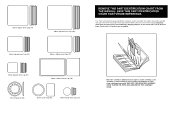
... BEGIN EACH ASSEMBLY STAGE TO OPEN THE PARTS BAG LABELED FOR THAT ASSEMBLY STAGE. 50mm Square Inner Cap (44) 60mm Square Inner Cap (101) This chart is provided to the key number of the part from the PART LIST in the centre of this manual. If you identify the small parts used in assembly. Important: Some parts may have been pre-assembled for each part refers to...
... BEGIN EACH ASSEMBLY STAGE TO OPEN THE PARTS BAG LABELED FOR THAT ASSEMBLY STAGE. 50mm Square Inner Cap (44) 60mm Square Inner Cap (101) This chart is provided to the key number of the part from the PART LIST in the centre of this manual. If you identify the small parts used in assembly. Important: Some parts may have been pre-assembled for each part refers to...
Instruction Manual
Page 16
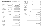
PART IDENTIFICATION CHART-Model No. WEEVSY59230 R1203A M10 Nylon Locknut (21) M8 Nylon Locknut (3) M10 x 45mm Bolt (100) M8 x 45mm Bolt (66) M10 x 22mm Bolt (98) M10 x 47mm Bolt (103) M6 x 50mm Screw (33) M10 x 52mm Bolt (12) M6 Nylon Locknut (2) M5 x 25mm Self-tapping Screw (80) M6 x 50mm Carriage Bolt (38) M6 x 16mm Screw (18) M10 x 60mm Bolt (7) M10 Washer (9) M10 x 63mm Bolt (107...
PART IDENTIFICATION CHART-Model No. WEEVSY59230 R1203A M10 Nylon Locknut (21) M8 Nylon Locknut (3) M10 x 45mm Bolt (100) M8 x 45mm Bolt (66) M10 x 22mm Bolt (98) M10 x 47mm Bolt (103) M6 x 50mm Screw (33) M10 x 52mm Bolt (12) M6 Nylon Locknut (2) M5 x 25mm Self-tapping Screw (80) M6 x 50mm Carriage Bolt (38) M6 x 16mm Screw (18) M10 x 60mm Bolt (7) M10 Washer (9) M10 x 63mm Bolt (107...
Instruction Manual
Page 17
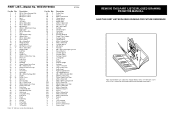
... Bumper Support Upright Carriage Large "U"-bracket Large Pulley Plate Ankle Strap Right Upright Bracket Left Upright Bracket M8 x 80mm Shoulder Bolt M10 Round Bushing 25mm Square Inner Cap M10 x 22mm Bolt M10 x 80mm Carriage Bolt M10 x 45mm Bolt 60mm Square Inner Cap M10 x 115mm Bolt M10 x 47mm Bolt M10 Thick Spacer Sleeve M10 x 105mm Bolt M10 x 63mm Bolt M10 x 158mm Bolt Eyebolt Key User's Manual Exercise Guide Exercise Chart Decal Grease Pack REMOVE THIS PART LIST...
... Bumper Support Upright Carriage Large "U"-bracket Large Pulley Plate Ankle Strap Right Upright Bracket Left Upright Bracket M8 x 80mm Shoulder Bolt M10 Round Bushing 25mm Square Inner Cap M10 x 22mm Bolt M10 x 80mm Carriage Bolt M10 x 45mm Bolt 60mm Square Inner Cap M10 x 115mm Bolt M10 x 47mm Bolt M10 Thick Spacer Sleeve M10 x 105mm Bolt M10 x 63mm Bolt M10 x 158mm Bolt Eyebolt Key User's Manual Exercise Guide Exercise Chart Decal Grease Pack REMOVE THIS PART LIST...

Instruction Manual
Page 18
... 40 4 14 96 40 28 32 34 30 21 34 30 92 67 31 31 19 53 19 69 100 96 21 27 1 EXPLODED DRAWING-Model No.
... 40 4 14 96 40 28 32 34 30 21 34 30 92 67 31 31 19 53 19 69 100 96 21 27 1 EXPLODED DRAWING-Model No.


