
English Manual
Page 1
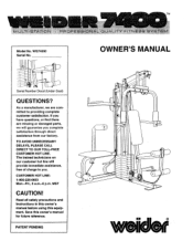
...! TO AVOID UNNECESSARY DELAYS, PLEASE CALL DIRECT TO OUR TOLL-FREE CUSTOMER HOT LINE. Read all safety precautions and instructions in this owner's manual before using this owner's manual for future reference. OWNER'S MANUAL Serial Number Decal (Under Seat) QUESTIONS? Save this equipment. TM Model No. If you have questions, or find there are missing or damaged parts, we are committed to you complete satisfaction...
...! TO AVOID UNNECESSARY DELAYS, PLEASE CALL DIRECT TO OUR TOLL-FREE CUSTOMER HOT LINE. Read all safety precautions and instructions in this owner's manual before using this owner's manual for future reference. OWNER'S MANUAL Serial Number Decal (Under Seat) QUESTIONS? Save this equipment. TM Model No. If you have questions, or find there are missing or damaged parts, we are committed to you complete satisfaction...
English Manual
Page 2
.... 2. Never release the arms, leg lever, military press/squat arm, ab arm, lat bar or nylon strap while weights are on all parts each time you use of this owner's manual and in this product. 2 Always disconnect the lat bar from the weight system when performing an exercise that the cables are raised. Never use the lat bar. 11. Use the weight system only on the pulleys at any time while exercising, stop immediately and make...
.... 2. Never release the arms, leg lever, military press/squat arm, ab arm, lat bar or nylon strap while weights are on all parts each time you use of this owner's manual and in this product. 2 Always disconnect the lat bar from the weight system when performing an exercise that the cables are raised. Never use the lat bar. 11. Use the weight system only on the pulleys at any time while exercising, stop immediately and make...
English Manual
Page 3
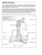
...): 72 in . Length (VKR Arms to achieve the specific results you , please note the product model number and serial number before using the WEIDER 7400 weight system. until 6 p.m. The serial number can be found on a decal attached to Ab Arm): 55 3/4 in . . 4, High Pulley Station Arms Ab Arm Ab Seat Footrest Weight Stack • • ■ . 0 • Weight Pin Foot Plates Military Press/Squat Arm Leg Lever Low Pulley Station 3 The model number is to develop every...
...): 72 in . Length (VKR Arms to achieve the specific results you , please note the product model number and serial number before using the WEIDER 7400 weight system. until 6 p.m. The serial number can be found on a decal attached to Ab Arm): 55 3/4 in . . 4, High Pulley Station Arms Ab Arm Ab Seat Footrest Weight Stack • • ■ . 0 • Weight Pin Foot Plates Military Press/Squat Arm Leg Lever Low Pulley Station 3 The model number is to develop every...
English Manual
Page 4
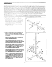
.... Before beginning assembly, read each step and look at each end of the weight system in the Footrest Frame (83). Press a 1" Round Cap (49) into the Base (4). 1 Attach the Pulley Plate (20) to the PART IDENTIFICATION CHART accompanying this owner's manual. Place all nuts and bolts as shown in the location where it has been pre-attached. For help identifying the small parts used . Press a 2" Inner...
.... Before beginning assembly, read each step and look at each end of the weight system in the Footrest Frame (83). Press a 1" Round Cap (49) into the Base (4). 1 Attach the Pulley Plate (20) to the PART IDENTIFICATION CHART accompanying this owner's manual. Place all nuts and bolts as shown in the location where it has been pre-attached. For help identifying the small parts used . Press a 2" Inner...
English Manual
Page 5
...1 4 11 0 3 8 . 82 96 0 , 5. Slide the 8" Pad onto the Ab Arm. 99 Grease the axle on the Ab Frame (96) with soapy water. Do not tighten the Nylock Nut yet. 96 . 4. Press a 3/4" Inner Cap (34) into each end of the Pad Tube. 5 34 A. Ab Frame ...96-Grease 0. . • .-7-.-; - 5 The lower end of the 10" Pad (100) with the 3/8" x 2 1/2" Bolt (70) and a 3/8" Jam Nut (6). 30 31 34 96 70 . - 85 .._ 6 30 6. Slide the Ab Arm (99) onto the axle. Attach the .. Attach a Wide 3 1/2" "V" Pulley (85) to the Rear Upright (82) with a 5/16" Nylock Nut (3). Press a ...
...1 4 11 0 3 8 . 82 96 0 , 5. Slide the 8" Pad onto the Ab Arm. 99 Grease the axle on the Ab Frame (96) with soapy water. Do not tighten the Nylock Nut yet. 96 . 4. Press a 3/4" Inner Cap (34) into each end of the Pad Tube. 5 34 A. Ab Frame ...96-Grease 0. . • .-7-.-; - 5 The lower end of the 10" Pad (100) with the 3/8" x 2 1/2" Bolt (70) and a 3/8" Jam Nut (6). 30 31 34 96 70 . - 85 .._ 6 30 6. Slide the Ab Arm (99) onto the axle. Attach the .. Attach a Wide 3 1/2" "V" Pulley (85) to the Rear Upright (82) with a 5/16" Nylock Nut (3). Press a ...
English Manual
Page 6
... the Top Frame (67). Attach the Front Upright to the Front Upright (42) with a 1/4" Flat Washer (10), onto the Carriage Bolt. N3 •82 3 42 ... .. .. * 1) 27 63 3 Tighten all Nylock Nuts used in steps 2 to the Rear Upright (82) with two 5/16" x 2 3/4" Carriage Bolts (14) and two 5/16" Nylock Nuts (3). 7. Attach the Stop Bracket (63) to the Base with a 1/4" x 2 1/4" Screw (103) and a 1/4" Flat...
... the Top Frame (67). Attach the Front Upright to the Front Upright (42) with a 1/4" Flat Washer (10), onto the Carriage Bolt. N3 •82 3 42 ... .. .. * 1) 27 63 3 Tighten all Nylock Nuts used in steps 2 to the Rear Upright (82) with two 5/16" x 2 3/4" Carriage Bolts (14) and two 5/16" Nylock Nuts (3). 7. Attach the Stop Bracket (63) to the Base with a 1/4" x 2 1/4" Screw (103) and a 1/4" Flat...
English Manual
Page 7
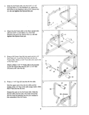
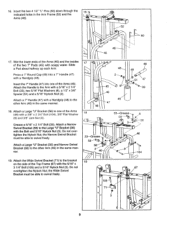
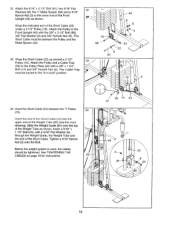
... ef) "weider" Logo on the side of the Rear Upright (82) with a 3/8" x 2 3/4" Bolt (104) and 3/8" Nylock Nut (6). 10 104 82 11. Press the Weight Tube Bumper (79) into the Weight Tube (80). 12 Insert the Weight Tube (80) into the stack of the Weight Tube. The Weight must be aligned with the holes in the Weight. 10. Attach the Military Press/Squat Arm (75...
... ef) "weider" Logo on the side of the Rear Upright (82) with a 3/8" x 2 3/4" Bolt (104) and 3/8" Nylock Nut (6). 10 104 82 11. Press the Weight Tube Bumper (79) into the Weight Tube (80). 12 Insert the Weight Tube (80) into the stack of the Weight Tube. The Weight must be aligned with the holes in the Weight. 10. Attach the Military Press/Squat Arm (75...
English Manual
Page 8
... the lower end of the axles. Attach the other Arm (46) to the top of the Arm must be between the two Arm Frame Bushings (68). Press two 1 3/4" Inner Caps (44) into the Arm Frame (52). Slide an Arm (46) onto one of the axle. The Arm Frame must be turned so the bracket is facing away from the Front Upright...
... the lower end of the axles. Attach the other Arm (46) to the top of the Arm must be between the two Arm Frame Bushings (68). Press two 1 3/4" Inner Caps (44) into the Arm Frame (52). Slide an Arm (46) onto one of the axle. The Arm Frame must be turned so the bracket is facing away from the Front Upright...
English Manual
Page 9
... up each Arm. Do not overtighten the Nylock Nut; Insert the two 4 1/2" "L" Pins (60) down through the 16 indicated holes in the same manner. 17 48 46 49 0 45 46 ,-51 47 -- . 8 c, 33 45 47 48 18 . 33-Grease 58----- )56 • 46 33-Grease ,6 58- 11. . 4.(. . 56 3 . ' - 46 6 -a! 104 19. Grease a 5/16" x 2 1/4" Bolt (33). Attach a Large...
... up each Arm. Do not overtighten the Nylock Nut; Insert the two 4 1/2" "L" Pins (60) down through the 16 indicated holes in the same manner. 17 48 46 49 0 45 46 ,-51 47 -- . 8 c, 33 45 47 48 18 . 33-Grease 58----- )56 • 46 33-Grease ,6 58- 11. . 4.(. . 56 3 . ' - 46 6 -a! 104 19. Grease a 5/16" x 2 1/4" Bolt (33). Attach a Large...
English Manual
Page 10
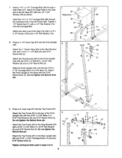
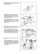
... two 3/8" Nylock Nuts (6). 77 o 12 21. Find the end of the Long Cable. Attach the Pulley to the Wide Swivel Bracket (71) with a 3/8" x 1 3/4" Bolt (12) and 3/8" Nylock Nut (6). 22 67 66 6 iv/ 15 ti 12 . . l l 23. Attach the Pulley and a Cable Trap (59) to the bracket with a 3/8" x 1 3/4" Bolt (12) anc 3/8" Nylock Nut (6). Insert the end of the Long...
... two 3/8" Nylock Nuts (6). 77 o 12 21. Find the end of the Long Cable. Attach the Pulley to the Wide Swivel Bracket (71) with a 3/8" x 1 3/4" Bolt (12) and 3/8" Nylock Nut (6). 22 67 66 6 iv/ 15 ti 12 . . l l 23. Attach the Pulley and a Cable Trap (59) to the bracket with a 3/8" x 1 3/4" Bolt (12) anc 3/8" Nylock Nut (6). Insert the end of the Long...
English Manual
Page 11
... the "3 o'clock" position. 66 15 58 12 59 46 12 9 3 27. The Cable Trap must be 12 86 0 pointed directly away from the Front Upright. 9 3 42 8 / 6 66 26. Wrap the Long Cable (66) around a 3 1/2" Pulley (15). Attach the Pulley and a Cable Trap (59) to the bracket with a 3/8" x 1 3/4" Bolt (12) and 3/8" Nylock Nut (6). a • 66 15 59 6 58 9 12 6 25...
... the "3 o'clock" position. 66 15 58 12 59 46 12 9 3 27. The Cable Trap must be 12 86 0 pointed directly away from the Front Upright. 9 3 42 8 / 6 66 26. Wrap the Long Cable (66) around a 3 1/2" Pulley (15). Attach the Pulley and a Cable Trap (59) to the bracket with a 3/8" x 1 3/4" Bolt (12) and 3/8" Nylock Nut (6). a • 66 15 59 6 58 9 12 6 25...
English Manual
Page 12
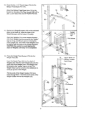
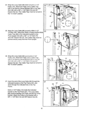
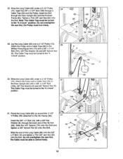
... Pulley and a Cable Trap (59) to the Rear Upright (82) with a 3/8" x 3 3/4" Bolt (106), 3/8" Flat Washer (9) and 3/8" Nylock Nut (6). Wrap the Long Cable (66) under a 3 1/2" Pulley (15). Wrap the Long Cable (66) under a 3 1/2" Pulley 30 (15). Attach the Pulley and a Cable Trap (59) to the Military Press/Squat Arm (75) with a 3/8" Flat 99 Washer (9), through the lower end of the Long Cable (66) onto the 3/8" x 3" Bolt (16) and tighten...
... Pulley and a Cable Trap (59) to the Rear Upright (82) with a 3/8" x 3 3/4" Bolt (106), 3/8" Flat Washer (9) and 3/8" Nylock Nut (6). Wrap the Long Cable (66) under a 3 1/2" Pulley (15). Wrap the Long Cable (66) under a 3 1/2" Pulley 30 (15). Attach the Pulley and a Cable Trap (59) to the Military Press/Squat Arm (75) with a 3/8" Flat 99 Washer (9), through the lower end of the Long Cable (66) onto the 3/8" x 3" Bolt (16) and tighten...
English Manual
Page 13
... 8 61 33. Before the weight system is used, the cables should be turned to the lower end of the Short Cable (23) under a 3 1/2" Pulley (15). Wrap the indicated end of the Front Upright (42) as shown. The Short Cable must be tightened. Wrap the Short Cable (23) up around a 3 1/2" Pulley (15). See TIGHTENING THE CABLES on page 19 for instructions. 23 15 23 12 78...
... 8 61 33. Before the weight system is used, the cables should be turned to the lower end of the Short Cable (23) under a 3 1/2" Pulley (15). Wrap the indicated end of the Front Upright (42) as shown. The Short Cable must be tightened. Wrap the Short Cable (23) up around a 3 1/2" Pulley (15). See TIGHTENING THE CABLES on page 19 for instructions. 23 15 23 12 78...
English Manual
Page 14
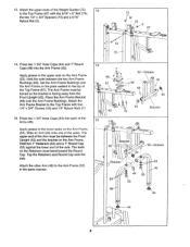
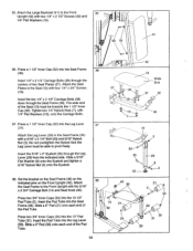
... Cap (32). Press a 1 1/2" Inner Cap (32) into the Leg Lever (29). Attach the Seat Plates to pivot freely. The wide end of the Pad Tube. ) . -....- -, 42 36 13 Wide End 37 38 . . ' . 37 32 o , 18 . the Leg Lever must be able to the Seat (13) with two 1/4" x 2 1/2" Screws (43) and...30 31 30 14 Tighten two 1/4" Nylock Nuts (7), with a 5/16" x 2 1/4" Bolt (33) and 5/16" Nylock Nut (3). Set the bracket on the Seat Frame (36) on the indicated pins on the Front Upright (42). Insert the Pad Tube into the Seat Frame (36). Attach the Seat Frame to the Seat Frame (36) with...
... Cap (32). Press a 1 1/2" Inner Cap (32) into the Leg Lever (29). Attach the Seat Plates to pivot freely. The wide end of the Pad Tube. ) . -....- -, 42 36 13 Wide End 37 38 . . ' . 37 32 o , 18 . the Leg Lever must be able to the Seat (13) with two 1/4" x 2 1/2" Screws (43) and...30 31 30 14 Tighten two 1/4" Nylock Nuts (7), with a 5/16" x 2 1/4" Bolt (33) and 5/16" Nylock Nut (3). Set the bracket on the Seat Frame (36) on the indicated pins on the Front Upright (42). Insert the Pad Tube into the Seat Frame (36). Attach the Seat Frame to the Seat Frame (36) with...
English Manual
Page 15
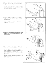
... same manner. 41. Attach the Handle to the Rear Upright with a 5/16" x 2" Bolt (91), two 5/16" Flat Washers (8), a 1/2" x 5/16" Spacer (50) and a 5/16" Nylock Nut (3) as shown. Attach a 7" Handle (47) to the Right VKR Arm (88) in the same manner. Attach a VKR Armrest (89) to the Rear Upright (82) with two 1/4" x 2" Screws (92) and 1/4" Flat Washers (10). Press two 1" Round Caps...
... same manner. 41. Attach the Handle to the Rear Upright with a 5/16" x 2" Bolt (91), two 5/16" Flat Washers (8), a 1/2" x 5/16" Spacer (50) and a 5/16" Nylock Nut (3) as shown. Attach a 7" Handle (47) to the Right VKR Arm (88) in the same manner. Attach a VKR Armrest (89) to the Rear Upright (82) with two 1/4" x 2" Screws (92) and 1/4" Flat Washers (10). Press two 1" Round Caps...
English Manual
Page 16
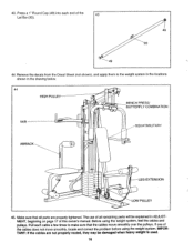
... pulleys. Press a 1" Round Cap (49) into each cable a few times to the weight system in the locations shown in ADJUSTMENT, beginning on page 17 of the 43 Lat Bar (93). 49 C 93 44. The use of all parts are not properly routed, they may be explained in the drawing below. 44 HIGH PULLEY BENCH PRESS/ BUTTERFLY COMBINATION VKR SQUAT/MILITARY AB/BACK ) e LEG EXTENSION . 0 S LOW PULLEY...
... pulleys. Press a 1" Round Cap (49) into each cable a few times to the weight system in the locations shown in ADJUSTMENT, beginning on page 17 of the 43 Lat Bar (93). 49 C 93 44. The use of all parts are not properly routed, they may be explained in the drawing below. 44 HIGH PULLEY BENCH PRESS/ BUTTERFLY COMBINATION VKR SQUAT/MILITARY AB/BACK ) e LEG EXTENSION . 0 S LOW PULLEY...
English Manual
Page 17
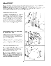
... the Arms (46) to the press mode by inserting one of the Weights (25). If there is any slack in the cable or chain as an exercise is not attached to the leg lever. Make sure to the Front Upright with the 5/16" x 2 3/4" Carriage Bolt (14) and Seat Knob (40). The weight setting can be adjusted. Note: Due to the cables and pulleys, the actual amount of resistance...
... the Arms (46) to the press mode by inserting one of the Weights (25). If there is any slack in the cable or chain as an exercise is not attached to the leg lever. Make sure to the Front Upright with the 5/16" x 2 3/4" Carriage Bolt (14) and Seat Knob (40). The weight setting can be adjusted. Note: Due to the cables and pulleys, the actual amount of resistance...
English Manual
Page 18
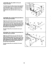
... Lat Bar and the Long Cable with a Cable Clip (95). ATTACHING THE LEG LEVER TO THE LOW PULLEY STATION To use the Leg Lever (29), the seat must be attached in the same manner. 29 95 35 23 0 94 23 95 39 94 93 66 95 93 94 39 18 The Nylon Strap (39) can be attached to the front upright (see ATTACHING AND REMOVING THE SEAT...
... Lat Bar and the Long Cable with a Cable Clip (95). ATTACHING THE LEG LEVER TO THE LOW PULLEY STATION To use the Leg Lever (29), the seat must be attached in the same manner. 29 95 35 23 0 94 23 95 39 94 93 66 95 93 94 39 18 The Nylon Strap (39) can be attached to the front upright (see ATTACHING AND REMOVING THE SEAT...
English Manual
Page 19
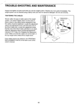
... the cables before resistance is first used. Pull the end of the Short Cable (23). Make sure that the cables are not too tight, or the top weight will be lifted off the weight stack. 15 Adjustment Screw 23 Ball 15 Adjustment Sleeve If the cables need to be cleaned using a damp cloth and mild non-abrasive detergent. TROUBLE-SHOOTING AND MAINTENANCE Inspect and tighten all parts...
... the cables before resistance is first used. Pull the end of the Short Cable (23). Make sure that the cables are not too tight, or the top weight will be lifted off the weight stack. 15 Adjustment Screw 23 Ball 15 Adjustment Sleeve If the cables need to be cleaned using a damp cloth and mild non-abrasive detergent. TROUBLE-SHOOTING AND MAINTENANCE Inspect and tighten all parts...
English Manual
Page 20
... cover of this owner's manual. The KEY NUMBER and DESCRIPTION of the part(s) from defects in Canada LIMITED WARRANTY Weider, Inc. ("WEIDER"), warrants this warranty is authorized by sufficient proof of purchase. All returns must be received by WEIDER at one of its authorized service centers with all freight and other rights which warranty claim is made must be prepared to be free from the PART LIST...
... cover of this owner's manual. The KEY NUMBER and DESCRIPTION of the part(s) from defects in Canada LIMITED WARRANTY Weider, Inc. ("WEIDER"), warrants this warranty is authorized by sufficient proof of purchase. All returns must be received by WEIDER at one of its authorized service centers with all freight and other rights which warranty claim is made must be prepared to be free from the PART LIST...


