
English Manual
Page 1
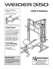
... precautions and instructions in the space above ) before using this manual for reference. USER'S MANUAL Visit our website at www.weiderfitness.com new products, prizes, fitness tips, and much more! As a manufacturer, we are missing, PLEASE DO NOT CONTACT THE STORE; please contact Customer Care. Save this equipment. IMPORTANT: You must note the product model number and serial number (see the...
... precautions and instructions in the space above ) before using this manual for reference. USER'S MANUAL Visit our website at www.weiderfitness.com new products, prizes, fitness tips, and much more! As a manufacturer, we are missing, PLEASE DO NOT CONTACT THE STORE; please contact Customer Care. Save this equipment. IMPORTANT: You must note the product model number and serial number (see the...
English Manual
Page 2
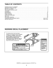
... BEGIN 4 PART IDENTIFICATION CHART 5 ASSEMBLY 6 ADJUSTMENT 18 MAINTENANCE 21 CABLE DIAGRAM 20 EXERCISE GUIDELINES 22 PART LIST 24 EXPLODED DRAWING 25 ORDERING REPLACEMENT PARTS Back Cover LIMITED WARRANTY Back Cover WARNING DECAL PLACEMENT The decals shown here have been applied in the location shown. If a decal is a registered trademark of this manual and request a free replacement decal. WEIDER is missing or illegible, call the telephone number on the front cover of ICON IP, Inc...
... BEGIN 4 PART IDENTIFICATION CHART 5 ASSEMBLY 6 ADJUSTMENT 18 MAINTENANCE 21 CABLE DIAGRAM 20 EXERCISE GUIDELINES 22 PART LIST 24 EXPLODED DRAWING 25 ORDERING REPLACEMENT PARTS Back Cover LIMITED WARRANTY Back Cover WARNING DECAL PLACEMENT The decals shown here have been applied in the location shown. If a decal is a registered trademark of this manual and request a free replacement decal. WEIDER is missing or illegible, call the telephone number on the front cover of ICON IP, Inc...
English Manual
Page 3
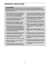
... users of the weight bench are mounted on the weight carriage, the barbell, or the weight tube on the weight bench before you feel pain or dizziness at all parts regular- 14. Always move the bench out of the way when performing an exercise that does not require the lat bar. 6. Always secure weights with a mat beneath it . Replace any exercise program, consult your physician. Do not use...
... users of the weight bench are mounted on the weight carriage, the barbell, or the weight tube on the weight bench before you feel pain or dizziness at all parts regular- 14. Always move the bench out of the way when performing an exercise that does not require the lat bar. 6. Always secure weights with a mat beneath it . Replace any exercise program, consult your physician. Do not use...
English Manual
Page 4
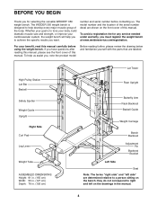
... group of this manual. they do not correspond to a person sitting on the drawings in . (193 cm) Lat Tower Rear Upright Butterfly Arm Rack Backrest Barbell Guide Weight Carriage Bench Backrest Adjustment Pin Backrest Bracket Left Side Seat Note: The terms "right side" and "left side" are labeled. High Pulley Station Lat Bar Barbell Safety Spotter Weight Guide Upright Right Side Curl Pad Leg Lever Weight Tube ASSEMBLED DIMENSIONS: Height: 61...
... group of this manual. they do not correspond to a person sitting on the drawings in . (193 cm) Lat Tower Rear Upright Butterfly Arm Rack Backrest Barbell Guide Weight Carriage Bench Backrest Adjustment Pin Backrest Bracket Left Side Seat Note: The terms "right side" and "left side" are labeled. High Pulley Station Lat Bar Barbell Safety Spotter Weight Guide Upright Right Side Curl Pad Leg Lever Weight Tube ASSEMBLED DIMENSIONS: Height: 61...
English Manual
Page 5
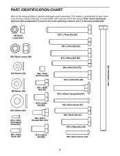
... Bolt (97) M6 x 63mm Screw (87) M8 x 60mm Bolt (91) M10 x 48mm Bolt (92) M6 x 40mm Screw (100) 5 Note: Some small parts may have been preattached. The number in parentheses by each drawing is not in assembly. If a part is the key number of the part, from the PART LIST near the end of this manual. PART IDENTIFICATION CHART Refer to the drawings below to identify small parts used...
... Bolt (97) M6 x 63mm Screw (87) M8 x 60mm Bolt (91) M10 x 48mm Bolt (92) M6 x 40mm Screw (100) 5 Note: Some small parts may have been preattached. The number in parentheses by each drawing is not in assembly. If a part is the key number of the part, from the PART LIST near the end of this manual. PART IDENTIFICATION CHART Refer to the drawings below to identify small parts used...
English Manual
Page 6
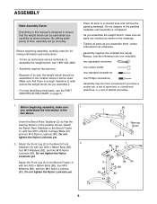
... remove the packing materials. Orient the Bench Rear Stabilizer (2) so that the warning decal is completed. • As you assemble the weight bench, make sure 1 you have a socket set, a set of open-end or closed-end wrenches, or a set of its size, the weight bench should be assembled in the location where it . • For help identifying small parts, use the PART IDENTIFICATION CHART on page 5. • Place all parts...
... remove the packing materials. Orient the Bench Rear Stabilizer (2) so that the warning decal is completed. • As you assemble the weight bench, make sure 1 you have a socket set, a set of open-end or closed-end wrenches, or a set of its size, the weight bench should be assembled in the location where it . • For help identifying small parts, use the PART IDENTIFICATION CHART on page 5. • Place all parts...

English Manual
Page 7
..., press the 25mm Round Angled Cap (19) onto the Weight Tube; Orient the two Backrest Frames (9) so the indi- 4 cated holes are closer to the Weight Tube (6) with an M8 x 10mm Set Screw (99). Do not tighten the Nylon Locknuts yet. 92 83 83 Holes 80 7 9 83 92 80 5. Attach the Olympic Adapter (22) to the bottom. the Leg...
..., press the 25mm Round Angled Cap (19) onto the Weight Tube; Orient the two Backrest Frames (9) so the indi- 4 cated holes are closer to the Weight Tube (6) with an M8 x 10mm Set Screw (99). Do not tighten the Nylon Locknuts yet. 92 83 83 Holes 80 7 9 83 92 80 5. Attach the Olympic Adapter (22) to the bottom. the Leg...
English Manual
Page 8
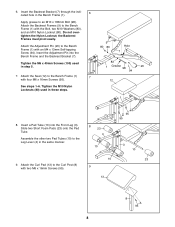
... 10 23 9. Attach the Adjustment Pin (20) to the Leg Lever (4) in the Bench Frame (1). Insert a Pad Tube (10) into the Bench Frame and the Backrest Bracket (7). Assemble the other two Pad Tubes (10) to the Bench Frame (1) with four M6 x 16mm Screws (95). 6. Do not overtighten the Nylon Locknut; Tighten the M6 x 40mm Screws (100) used in step 5. 7. Attach the Seat (12) to the...
... 10 23 9. Attach the Adjustment Pin (20) to the Leg Lever (4) in the Bench Frame (1). Insert a Pad Tube (10) into the Bench Frame and the Backrest Bracket (7). Assemble the other two Pad Tubes (10) to the Bench Frame (1) with four M6 x 16mm Screws (95). 6. Do not overtighten the Nylon Locknut; Tighten the M6 x 40mm Screws (100) used in step 5. 7. Attach the Seat (12) to the...
English Manual
Page 11
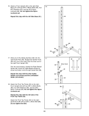
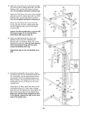
...one of the holes near the lower end of the right Front Upright (29). Identify the Right Barbell Guide (36). Repeat this step with two M10 x 68mm Bolts (85), four M10 Washers (83), and two M10 Nylon Locknuts (80). Attach the Front Top Frame (30) to the right Guide Rod (28) with the left ... onto the 17 right Guide Rod (28). Do not tighten the Nylon Locknuts yet. 16. Do not tighten the Nylon Locknuts yet. Repeat this step with an M10 x 25mm Bolt (86). Do not tighten the Bolt. 86 30 28 83 85 83 80 29 11 Repeat this step with two M10 x 68mm Bolts (85), four M10 ...
...one of the holes near the lower end of the right Front Upright (29). Identify the Right Barbell Guide (36). Repeat this step with two M10 x 68mm Bolts (85), four M10 Washers (83), and two M10 Nylon Locknuts (80). Attach the Front Top Frame (30) to the right Guide Rod (28) with the left ... onto the 17 right Guide Rod (28). Do not tighten the Nylon Locknuts yet. 16. Do not tighten the Nylon Locknuts yet. Repeat this step with an M10 x 25mm Bolt (86). Do not tighten the Bolt. 86 30 28 83 85 83 80 29 11 Repeat this step with two M10 x 68mm Bolts (85), four M10 ...
English Manual
Page 12
...95 64 12 Attach the Top Frame (31) to the Rear Upright (27) with two M10 x 68mm Bolts (85), two M10 Washers (83), and two M10 Nylon Locknuts (80). See the inset drawing. Next, slide a Weight Stop (64) onto the Barbell (42). Repeat this step for the Left Butterfly Arm (33). ...) into the Weight Stop. Orient the Locking Bar (43) as shown. Orient the Retainer Rings with the teeth toward the Butterfly Arm Cap. Tighten the M10 and M8 Nylon Locknuts (80, 81) used in steps 10-19, and the M10 x 25mm Bolts (86) used in the Barbell. Hand tighten an M6 x 16mm Screw (95) into...
...95 64 12 Attach the Top Frame (31) to the Rear Upright (27) with two M10 x 68mm Bolts (85), two M10 Washers (83), and two M10 Nylon Locknuts (80). See the inset drawing. Next, slide a Weight Stop (64) onto the Barbell (42). Repeat this step for the Left Butterfly Arm (33). ...) into the Weight Stop. Orient the Locking Bar (43) as shown. Orient the Retainer Rings with the teeth toward the Butterfly Arm Cap. Tighten the M10 and M8 Nylon Locknuts (80, 81) used in steps 10-19, and the M10 x 25mm Bolts (86) used in the Barbell. Hand tighten an M6 x 16mm Screw (95) into...
English Manual
Page 13
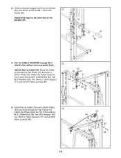
... an M10 Nylon Locknut (80). 55 80 83 31 77 83 74 77 85 13 Route the Lat Cable (74) over a 90mm Pulley (55). Slide an Olympic Adapter (22) onto the Barbell (42) and secure it with an M10 x 68mm Bolt (85), two M10 Washers (83), two 16mm x 13mm Spacers (77), and an M10... (42). 42 22 99 23. Route the Cable up through the Top Frame (31) and over a 90mm Pulley 24 (55) and down through the Top Frame (31). Attach the Pulley inside the Top Frame with an M8 x 10mm Set 22 Screw (99). See the CABLE DIAGRAM on page 20 to 23 identify the cables as you assemble them. 22.
... an M10 Nylon Locknut (80). 55 80 83 31 77 83 74 77 85 13 Route the Lat Cable (74) over a 90mm Pulley (55). Slide an Olympic Adapter (22) onto the Barbell (42) and secure it with an M10 x 68mm Bolt (85), two M10 Washers (83), two 16mm x 13mm Spacers (77), and an M10... (42). 42 22 99 23. Route the Cable up through the Top Frame (31) and over a 90mm Pulley 24 (55) and down through the Top Frame (31). Attach the Pulley inside the Top Frame with an M8 x 10mm Set 22 Screw (99). See the CABLE DIAGRAM on page 20 to 23 identify the cables as you assemble them. 22.
English Manual
Page 17
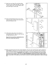
... the cables are not properly installed, they may be explained in the cables, you will need to remove the slack by tightening the cables (see page 21). 17 If there is used. Slide the Foam Pad onto the Right Butterfly Arm (34). Attach the Rack Backrest (45) to the inside of the cables does not move smoothly over the pulleys. See the CABLE DIAGRAM on...
... the cables are not properly installed, they may be explained in the cables, you will need to remove the slack by tightening the cables (see page 21). 17 If there is used. Slide the Foam Pad onto the Right Butterfly Arm (34). Attach the Rack Backrest (45) to the inside of the cables does not move smoothly over the pulleys. See the CABLE DIAGRAM on...
English Manual
Page 18
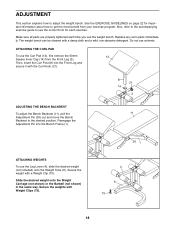
... Square Inner Cap (14) from your exercise program. ATTACHING THE CURL PAD To use the weight bench. ADJUSTMENT This section explains how to get the most benefit from the Front Leg (3). Secure the weight with the Curl Knob (21). 8 21 14 3 ADJUSTING THE BENCH BACKREST To adjust the Bench Backrest (11), pull the 11 Adjustment Pin (20) out and move the Bench Backrest to the desired position. Slide...
... Square Inner Cap (14) from your exercise program. ATTACHING THE CURL PAD To use the weight bench. ADJUSTMENT This section explains how to get the most benefit from the Front Leg (3). Secure the weight with the Curl Knob (21). 8 21 14 3 ADJUSTING THE BENCH BACKREST To adjust the Bench Backrest (11), pull the 11 Adjustment Pin (20) out and move the Bench Backrest to the desired position. Slide...

English Manual
Page 19
... the Lat Bar with a Cable Clip, and 72 attach another link of the weight rack and grip the Locking Bar (43) with both hands. WARNING: Always adjust the Safety Spotters (38) to the Low Cable (not shown) in the correct position for the exercise. Note: For some exercises, you will move during the exercise. 37 38 29 Position the Safety Spotters (38) directly...
... the Lat Bar with a Cable Clip, and 72 attach another link of the weight rack and grip the Locking Bar (43) with both hands. WARNING: Always adjust the Safety Spotters (38) to the Low Cable (not shown) in the correct position for the exercise. Note: For some exercises, you will move during the exercise. 37 38 29 Position the Safety Spotters (38) directly...
English Manual
Page 20
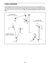
If the cables have been assembled correctly. The numbers show the proper routing of the Lat Cable, the Low Cable, and the Butterfly Cable. CABLE DIAGRAM The cable diagrams below show the correct route for each cable. Make sure that the cables, the cable traps, and the guards have not been correctly routed, the weight system will not function properly and damage may occur. Lat Cable (74) Length: 11 ft. 11...
If the cables have been assembled correctly. The numbers show the proper routing of the Lat Cable, the Low Cable, and the Butterfly Cable. CABLE DIAGRAM The cable diagrams below show the correct route for each cable. Make sure that the cables, the cable traps, and the guards have not been correctly routed, the weight system will not function properly and damage may occur. Lat Cable (74) Length: 11 ft. 11...

English Manual
Page 21
... weights to hold the cable in the groove of the Pulley Plates. MAINTENANCE Make sure all parts are oriented as shown, and that the Cable and Pulley move smoothly. 92 58 61 59 58 80 55 Do not overtighten the cable. TIGHTENING THE CABLES Woven cable, the type of this manual. Remove the cable and re-install it may have become twisted. See ATTACHING WEIGHTS in the cables before resistance...
... weights to hold the cable in the groove of the Pulley Plates. MAINTENANCE Make sure all parts are oriented as shown, and that the Cable and Pulley move smoothly. 92 58 61 59 58 80 55 Do not overtighten the cable. TIGHTENING THE CABLES Woven cable, the type of this manual. Remove the cable and re-install it may have become twisted. See ATTACHING WEIGHTS in the cables before resistance...
English Manual
Page 22
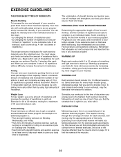
... what is the highest. To give your body time to regenerate. Weight Loss To lose weight, use a low amount of resistance and increase the number of repetitions in each exercise, and moving only the appropriate parts of the body. Schedule your workouts for each set . EXERCISE FORM Maintaining proper form is an essential part of a balanced program is: • Plan strength training workouts on Monday, Wednesday, and Friday. •...
... what is the highest. To give your body time to regenerate. Weight Loss To lose weight, use a low amount of resistance and increase the number of repetitions in each exercise, and moving only the appropriate parts of the body. Schedule your workouts for each set . EXERCISE FORM Maintaining proper form is an essential part of a balanced program is: • Plan strength training workouts on Monday, Wednesday, and Friday. •...

English Manual
Page 23
... minutes after each set for a muscle building workout. • Rest for one minute after each set for a weight loss workout. out. • Rest for 30 seconds after each set. The key to spend the first couple of thigh) I J K L M N O P Q R S T U V W X MUSCLE CHART A. Pectoralis Major (chest) C. Obliques (waist) E. Quadriceps (front of weeks familiarizing yourself with 5 to make exercise a regular and enjoyable part of each...
... minutes after each set for a muscle building workout. • Rest for one minute after each set for a weight loss workout. out. • Rest for 30 seconds after each set. The key to spend the first couple of thigh) I J K L M N O P Q R S T U V W X MUSCLE CHART A. Pectoralis Major (chest) C. Obliques (waist) E. Quadriceps (front of weeks familiarizing yourself with 5 to make exercise a regular and enjoyable part of each...
English Manual
Page 24
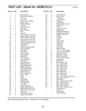
... Bolt M8 x 60mm Bolt M10 x 48mm Bolt M8 x 70mm Bolt M4 x 13mm Self-tapping Screw M6 x 16mm Screw M6 Washer M10 x 62mm Carriage Bolt M10 x 183mm Bolt M8 x 10mm Set Screw M6 x 40mm Screw M8 x 22mm Shoulder Bolt User's Manual Hex Key Grease Pack Exercise Guide Note: Specifications are not illustrated. 24 Qty. Qty. PART LIST-Model No. Description Key No. WEBE1915.0 R0907A Key No. See the back cover of this manual for information about ordering replacement parts. *These parts...
... Bolt M8 x 60mm Bolt M10 x 48mm Bolt M8 x 70mm Bolt M4 x 13mm Self-tapping Screw M6 x 16mm Screw M6 Washer M10 x 62mm Carriage Bolt M10 x 183mm Bolt M8 x 10mm Set Screw M6 x 40mm Screw M8 x 22mm Shoulder Bolt User's Manual Hex Key Grease Pack Exercise Guide Note: Specifications are not illustrated. 24 Qty. Qty. PART LIST-Model No. Description Key No. WEBE1915.0 R0907A Key No. See the back cover of this manual for information about ordering replacement parts. *These parts...
English Manual
Page 28
... service centers. products used as store display models. ICON HEALTH & FITNESS, INC., 1500 S. 1000 W., LOGAN, UT 84321-9813 Part No. 231070 R0907A Printed in -home service, the customer will be the customer's responsibility. Some states do not allow limitations on how long an implied warranty lasts. ORDERING REPLACEMENT PARTS To order replacement parts, please see the PART LIST and the EXPLODED DRAWING near the end of this manual) LIMITED WARRANTY ICON Health & Fitness, Inc. (ICON...
... service centers. products used as store display models. ICON HEALTH & FITNESS, INC., 1500 S. 1000 W., LOGAN, UT 84321-9813 Part No. 231070 R0907A Printed in -home service, the customer will be the customer's responsibility. Some states do not allow limitations on how long an implied warranty lasts. ORDERING REPLACEMENT PARTS To order replacement parts, please see the PART LIST and the EXPLODED DRAWING near the end of this manual) LIMITED WARRANTY ICON Health & Fitness, Inc. (ICON...


