

English Manual
Page 1
...-999-3756 Mon.-Fri., 6 a.m.-6 p.m. USER'S MANUAL Visit our website at www.weiderfitness.com new products, prizes, fitness tips, and much more! As a manufacturer, we are missing or damaged parts, we will provide immediate assistance, free of charge to providing complete customer satisfaction. The trained technicians on our customer hot line will guarantee you . Model No. Serial Number Decal QUESTIONS?
...-999-3756 Mon.-Fri., 6 a.m.-6 p.m. USER'S MANUAL Visit our website at www.weiderfitness.com new products, prizes, fitness tips, and much more! As a manufacturer, we are missing or damaged parts, we will provide immediate assistance, free of charge to providing complete customer satisfaction. The trained technicians on our customer hot line will guarantee you . Model No. Serial Number Decal QUESTIONS?

English Manual
Page 2
... CHART and PART LIST/EXPLODED DRAWING before beginning assembly. TABLE OF CONTENTS WARNING DECAL PLACEMENT 2 IMPORTANT PRECAUTIONS 3 BEFORE YOU BEGIN 4 ASSEMBLY 5 ADJUSTMENTS 8 EXERCISE GUIDELINES 9 ORDERING REPLACEMENT PARTS Back Cover LIMITED WARRANTY Back Cover Note: A PART IDENTIFICATION CHART and a PART LIST/EXPLODED DRAWING are attached in the location shown. Apply the decal in the center of this area. Keep hands and fingers clear of ICON Health & Fitness, Inc. 2 Mountain Time, to order a free replacement decal. WEIDER...
... CHART and PART LIST/EXPLODED DRAWING before beginning assembly. TABLE OF CONTENTS WARNING DECAL PLACEMENT 2 IMPORTANT PRECAUTIONS 3 BEFORE YOU BEGIN 4 ASSEMBLY 5 ADJUSTMENTS 8 EXERCISE GUIDELINES 9 ORDERING REPLACEMENT PARTS Back Cover LIMITED WARRANTY Back Cover Note: A PART IDENTIFICATION CHART and a PART LIST/EXPLODED DRAWING are attached in the location shown. Apply the decal in the center of this area. Keep hands and fingers clear of ICON Health & Fitness, Inc. 2 Mountain Time, to order a free replacement decal. WEIDER...

English Manual
Page 3
... all parts are using the weight bench. Read all precautions. 3. Replace any commercial, rental, or institutional setting. 4. Never use the weight bench in this manual before using the leg lever, place a barbell with pre-existing health problems. Read all times. 7. IMPORTANT PRECAUTIONS WARNING: To reduce the risk of your physician. Use the weight bench only as described in any worn parts immediately. 6. The weight bench is designed to support a maximum user weight of...
... all parts are using the weight bench. Read all precautions. 3. Replace any commercial, rental, or institutional setting. 4. Never use the weight bench in this manual before using the leg lever, place a barbell with pre-existing health problems. Read all times. 7. IMPORTANT PRECAUTIONS WARNING: To reduce the risk of your physician. Use the weight bench only as described in any worn parts immediately. 6. The weight bench is designed to support a maximum user weight of...

English Manual
Page 4
... versatile WEIDER® 120 weight bench is designed to the weight bench (see the front cover of the body. Whether your benefit, read this manual). Depth: 58.0 in . Mountain Time (excluding holidays). Barbell Backrest Weight Rests Lock Collar Uprights Support Rod Leg Lever Weight Tube Seat ASSEMBLED DIMENSIONS: Height: 44.5 in. toll-free at the drawing below and familiarize yourself with the parts that are labeled. The model number is a shapely...
... versatile WEIDER® 120 weight bench is designed to the weight bench (see the front cover of the body. Whether your benefit, read this manual). Depth: 58.0 in . Mountain Time (excluding holidays). Barbell Backrest Weight Rests Lock Collar Uprights Support Rod Leg Lever Weight Tube Seat ASSEMBLED DIMENSIONS: Height: 44.5 in. toll-free at the drawing below and familiarize yourself with the parts that are labeled. The model number is a shapely...
English Manual
Page 5
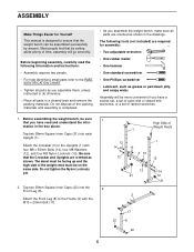
... Caps (22) into each Upright (1). High Side of the weight rests must be sure 1 that by anyone. Before assembling the weight bench, be on the same side. The following information and instructions: • Assembly requires two people. • For help identifying small parts refer to the PART IDENTIFICATION CHART. • Tighten all parts as you have a socket set, a set of open-end or closed-end wrenches...
... Caps (22) into each Upright (1). High Side of the weight rests must be sure 1 that by anyone. Before assembling the weight bench, be on the same side. The following information and instructions: • Assembly requires two people. • For help identifying small parts refer to the PART IDENTIFICATION CHART. • Tighten all parts as you have a socket set, a set of open-end or closed-end wrenches...

English Manual
Page 6
... Inner Cap (24) into the holes in the Leg Lever (4). Lubricate the M10 x 60mm Bolt (18). Insert the Pad Tubes into the indi- cated end of the weight 22 tube. Attach the Leg Lever (4) to the Crossbar (3) with the Bolt and the M10 Nylon Locknut (19). Slide two Foam... Pads (23) onto each 6 Pad Tube (10). Attach the Frame (2) to the Frame (2) with two M8 x 55mm Bolts (14), 1 two M8 Washers (12), and two M8 Nylon Locknuts (13). Do not tighten...
... Inner Cap (24) into the holes in the Leg Lever (4). Lubricate the M10 x 60mm Bolt (18). Insert the Pad Tubes into the indi- cated end of the weight 22 tube. Attach the Leg Lever (4) to the Crossbar (3) with the Bolt and the M10 Nylon Locknut (19). Slide two Foam... Pads (23) onto each 6 Pad Tube (10). Attach the Frame (2) to the Frame (2) with two M8 x 55mm Bolts (14), 1 two M8 Washers (12), and two M8 Nylon Locknuts (13). Do not tighten...

English Manual
Page 7
... (26). Attach the Seat (11) to the Backrest (6) with one M6 x 38mm Screw and one M6 Washer. Note: Do not tighten the three Screws yet. The use the weight bench. Press two 25mm Round Inner Caps (24) into 7 the ends of holes in steps 1 and 3. 9. Attach one of the four sets of the Backrest Tubes (5). See the inset drawing. Rotate the Support Rod...
... (26). Attach the Seat (11) to the Backrest (6) with one M6 x 38mm Screw and one M6 Washer. Note: Do not tighten the three Screws yet. The use the weight bench. Press two 25mm Round Inner Caps (24) into 7 the ends of holes in steps 1 and 3. 9. Attach one of the four sets of the Backrest Tubes (5). See the inset drawing. Rotate the Support Rod...

English Manual
Page 8
...) on the Leg Lever (9). 1 6 1 7 2 4 Weight Tube 27, 28 ATTACHING WEIGHTS TO THE BARBELL Slide an equal amount of Weight (27, 28) onto each time the weight bench is used in an inclined position, first lift the Backrest. ADJUSTMENTS The steps below explain how the weight bench can be used . Insert the Support Rod (7) through the bottom set of the barbell. Replace any worn parts immediately. ADJUSTING THE BACKREST The...
...) on the Leg Lever (9). 1 6 1 7 2 4 Weight Tube 27, 28 ATTACHING WEIGHTS TO THE BARBELL Slide an equal amount of Weight (27, 28) onto each time the weight bench is used in an inclined position, first lift the Backrest. ADJUSTMENTS The steps below explain how the weight bench can be used . Insert the Support Rod (7) through the bottom set of the barbell. Replace any worn parts immediately. ADJUSTING THE BACKREST The...

English Manual
Page 9
... discomfort. You must gauge your limits and select the amount of weight that is : • Plan weight training workouts on Tuesday and Thursday. • Rest from session to session. Work your body's signals. formed. (A "repetition" is the highest. The repetitions in any time while exercising, stop immediately and begin cooling down. Schedule your workouts for several exercises, and a list of the muscles affected...
... discomfort. You must gauge your limits and select the amount of weight that is : • Plan weight training workouts on Tuesday and Thursday. • Rest from session to session. Work your body's signals. formed. (A "repetition" is the highest. The repetitions in any time while exercising, stop immediately and begin cooling down. Schedule your workouts for several exercises, and a list of the muscles affected...

English Manual
Page 10
... far as you can be photocopied and used , and the numbers of your arms and legs. COOLING DOWN End each workout with the equipment and learning the proper form for both your everyday life. Ease into each set for a toning work- Sternomastoid (neck) B. Biceps (front...each workout is to schedule and record your weight and key body measurements at the end of calf) N O P Q R S T U V W 10 Trapezius (upper back) H O. Latissimus Dorsi (mid back) J S. List the date, the exercises performed, the weight used to make exercise a regular and enjoyable part of sets and...
... far as you can be photocopied and used , and the numbers of your arms and legs. COOLING DOWN End each workout with the equipment and learning the proper form for both your everyday life. Ease into each set for a toning work- Sternomastoid (neck) B. Biceps (front...each workout is to schedule and record your weight and key body measurements at the end of calf) N O P Q R S T U V W 10 Trapezius (upper back) H O. Latissimus Dorsi (mid back) J S. List the date, the exercises performed, the weight used to make exercise a regular and enjoyable part of sets and...

English Manual
Page 11
MONDAY Date: / / EXERCISE WEIGHT SETS REPS TUESDAY Date: / / AEROBIC EXERCISE WEDNESDAY Date: / / EXERCISE WEIGHT SETS REPS THURSDAY Date: / / AEROBIC EXERCISE FRIDAY Date: / / EXERCISE WEIGHT SETS REPS Make photocopies of this page for scheduling and recording your workouts. 11
MONDAY Date: / / EXERCISE WEIGHT SETS REPS TUESDAY Date: / / AEROBIC EXERCISE WEDNESDAY Date: / / EXERCISE WEIGHT SETS REPS THURSDAY Date: / / AEROBIC EXERCISE FRIDAY Date: / / EXERCISE WEIGHT SETS REPS Make photocopies of this page for scheduling and recording your workouts. 11

English Manual
Page 12
... SERIAL NUMBER of the product (see the front cover of this manual) • The KEY NUMBER and DESCRIPTION of the desired part(s) (see the PART LIST and EXPLODED DRAWING in the center of the product or damages with the use and service conditions, for a particular purpose is in lieu of incidental or consequential damages. ICON's obligation under normal use or performance of this manual) LIMITED WARRANTY ICON Health & Fitness...
... SERIAL NUMBER of the product (see the front cover of this manual) • The KEY NUMBER and DESCRIPTION of the desired part(s) (see the PART LIST and EXPLODED DRAWING in the center of the product or damages with the use and service conditions, for a particular purpose is in lieu of incidental or consequential damages. ICON's obligation under normal use or performance of this manual) LIMITED WARRANTY ICON Health & Fitness...

English Manual
Page 13
REMOVE THIS PART IDENTIFICATION CHART PART LIST/EXPLODED DRAWING SAVE THIS PART IDENTIFICATION CHART PART LIST/EXPLODED DRAWING FOR FUTURE REFERENCE 81
REMOVE THIS PART IDENTIFICATION CHART PART LIST/EXPLODED DRAWING SAVE THIS PART IDENTIFICATION CHART PART LIST/EXPLODED DRAWING FOR FUTURE REFERENCE 81

English Manual
Page 14
M10 x 60mm Bolt (18) M8 x 55mm Bolt (14) M6 x 38mm Screw (16) M10 Nylon Locknut (19) M8 Washer (12) M8 Nylon Locknut (13) M10 x 20mm Bolt (17) M6 x 16mm Screw (15) M6 Washer (26) PART IDENTIFICATION CHART This chart is provided to help you cannot find a part in the parts bags, check to the key number of the part, from the PART LIST in assembly. The number in parenthesis below each part refers to see if it has been pre-assembled. If you identify the small parts used in the center of this manual. Important: Some parts may have been pre-assembled for shipping purposes.
M10 x 60mm Bolt (18) M8 x 55mm Bolt (14) M6 x 38mm Screw (16) M10 Nylon Locknut (19) M8 Washer (12) M8 Nylon Locknut (13) M10 x 20mm Bolt (17) M6 x 16mm Screw (15) M6 Washer (26) PART IDENTIFICATION CHART This chart is provided to help you cannot find a part in the parts bags, check to the key number of the part, from the PART LIST in assembly. The number in parenthesis below each part refers to see if it has been pre-assembled. If you identify the small parts used in the center of this manual. Important: Some parts may have been pre-assembled for shipping purposes.

English Manual
Page 15
PART LIST-Model No. Specifications are subject to change without notice. See the back cover of this manual for information about ordering replacement parts. WEBE09420 R1002A Key No. Qty. Description Key No. Qty. Description 1 2 Upright 2 1 Frame 3 1 Crossbar 4 1 Leg Lever 5 2 Backrest Tube 6 1 Backrest 7 1 Support Rod 8 1 Front Leg 9 6 19mm Round Inner Cap 10 2 Pad Tube 11 1 Seat 12 6 M8 Washer 13 6 M8 Nylon Locknut 14 6 M8 x 55mm Bolt 15 4 M6 x 16mm...
PART LIST-Model No. Specifications are subject to change without notice. See the back cover of this manual for information about ordering replacement parts. WEBE09420 R1002A Key No. Qty. Description Key No. Qty. Description 1 2 Upright 2 1 Frame 3 1 Crossbar 4 1 Leg Lever 5 2 Backrest Tube 6 1 Backrest 7 1 Support Rod 8 1 Front Leg 9 6 19mm Round Inner Cap 10 2 Pad Tube 11 1 Seat 12 6 M8 Washer 13 6 M8 Nylon Locknut 14 6 M8 x 55mm Bolt 15 4 M6 x 16mm...

English Manual
Page 16
EXPLODED DRAWING-Model No. WEBE09420 R1002A 9 7 6 25 26 16 5 12 26 14 25 16 11 12 13 2 26 9 1 1 13 14 14 12 13 13 3 21 12 14 12 15 8 17 30 23 18 4 22 22 24 32 19 22 20 9 24 22 10 9 9 23 31 29 21 32 24 27 28
EXPLODED DRAWING-Model No. WEBE09420 R1002A 9 7 6 25 26 16 5 12 26 14 25 16 11 12 13 2 26 9 1 1 13 14 14 12 13 13 3 21 12 14 12 15 8 17 30 23 18 4 22 22 24 32 19 22 20 9 24 22 10 9 9 23 31 29 21 32 24 27 28


