
User Manual
Page 1
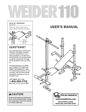
... are missing parts, we will provide immediate assistance, free of charge to you have questions, or if there are committed to providing complete customer satisfaction. Write the serial number in this manual before using this manual for future reference. MST CAUTION Read all precautions and instructions in the space above for future reference. TO AVOID DELAYS, PLEASE CALL DIRECT TO...
... are missing parts, we will provide immediate assistance, free of charge to you have questions, or if there are committed to providing complete customer satisfaction. Write the serial number in this manual before using this manual for future reference. MST CAUTION Read all precautions and instructions in the space above for future reference. TO AVOID DELAYS, PLEASE CALL DIRECT TO...
User Manual
Page 2
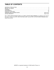
Remove the PART IDENTIFICATION CHART and the PART LIST/EXPLODED DRAWING before beginning assembly. WEIDER is a registered trademark of this manual. TABLE OF CONTENTS IMPORTANT PRECAUTIONS 3 BEFORE YOU BEGIN 4 ASSEMBLY 5 ADJUSTMENTS 10 EXERCISE GUIDELINES 13 ORDERING REPLACEMENT PARTS Back Cover LIMITED WARRANTY Back Cover Note: A PART IDENTIFICATION CHART and a PART LIST/EXPLODED DRAWING are attached in the center of ICON Health & Fitness, Inc. 2
Remove the PART IDENTIFICATION CHART and the PART LIST/EXPLODED DRAWING before beginning assembly. WEIDER is a registered trademark of this manual. TABLE OF CONTENTS IMPORTANT PRECAUTIONS 3 BEFORE YOU BEGIN 4 ASSEMBLY 5 ADJUSTMENTS 10 EXERCISE GUIDELINES 13 ORDERING REPLACEMENT PARTS Back Cover LIMITED WARRANTY Back Cover Note: A PART IDENTIFICATION CHART and a PART LIST/EXPLODED DRAWING are attached in the center of ICON Health & Fitness, Inc. 2

User Manual
Page 3
... with pre-existing health problems. Read all times. 7. Read all instructions in the locations shown on a level surface. 15. Always make sure that the support rod is inserted completely through the uprights and turned to order a free replacement decal. Always remove the lat bar when performing an exercise that all parts are adequately informed of all users of the weight bench are properly tightened each fly arm. ing down. 5. Always...
... with pre-existing health problems. Read all times. 7. Read all instructions in the locations shown on a level surface. 15. Always make sure that the support rod is inserted completely through the uprights and turned to order a free replacement decal. Always remove the lat bar when performing an exercise that all parts are adequately informed of all users of the weight bench are properly tightened each fly arm. ing down. 5. Always...
User Manual
Page 4
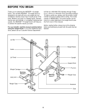
For your benefit, read this manual). If you want. Lat Bar Cable Lat Tower Weight Carriage Warning Decal 2 Leg Lever Weight Tube Warning Decal 1 Weight Rests Upright Support Rod Fly Arm Weight Tube Backrest Seat 4 To help you to achieve the specific results you have additional questions, please call our Customer Service Department toll-free at the drawing below and familiarize yourself with your goal is WEBE03820. BEFORE...
For your benefit, read this manual). If you want. Lat Bar Cable Lat Tower Weight Carriage Warning Decal 2 Leg Lever Weight Tube Warning Decal 1 Weight Rests Upright Support Rod Fly Arm Weight Tube Backrest Seat 4 To help you to achieve the specific results you have additional questions, please call our Customer Service Department toll-free at the drawing below and familiarize yourself with your goal is WEBE03820. BEFORE...
User Manual
Page 5
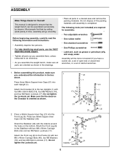
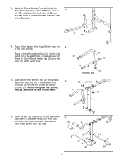
... small parts, use the PART IDENTIFICATION CHART. • Tighten all parts in the drawings. • Place all parts as you assemble them, unless instructed to the Frame (2) with four M8 x 55mm Bolts (18), four M8 Washers (16), and four M8 Nylon Locknuts (17). Press a 38mm Square Inner Cap (21) into the Front Leg (8). Attach the Front Leg (8) to do otherwise. • As you assemble the weight bench...
... small parts, use the PART IDENTIFICATION CHART. • Tighten all parts in the drawings. • Place all parts as you assemble them, unless instructed to the Frame (2) with four M8 x 55mm Bolts (18), four M8 Washers (16), and four M8 Nylon Locknuts (17). Press a 38mm Square Inner Cap (21) into the Front Leg (8). Attach the Front Leg (8) to do otherwise. • As you assemble the weight bench...
User Manual
Page 6
... the Leg Lever (4). the Leg Lever must be able to the Crossbar (3) with two 3 M8 x 55mm Bolts (18) and two M8 Nylon Locknuts (17). Tap a 30mm Square Inner Cap (22) into the indicated end of the weight tube. 4 22 20 24 22 Weight Tube 5. Do not tighten the Locknuts yet. Attach the Frame (2) to pivot easily. 5 32 Lubricate...
... the Leg Lever (4). the Leg Lever must be able to the Crossbar (3) with two 3 M8 x 55mm Bolts (18) and two M8 Nylon Locknuts (17). Tap a 30mm Square Inner Cap (22) into the indicated end of the weight tube. 4 22 20 24 22 Weight Tube 5. Do not tighten the Locknuts yet. Attach the Frame (2) to pivot easily. 5 32 Lubricate...
User Manual
Page 7
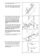
... the Upright. Press a 25mm Round 10 Inner Cap (24) into the ends of the Support Rod (7). Attach the Seat (11) to pivot easily. Attach the Backrest Tubes (5) to 3. 9. Slide a Weight Stop (28) onto the weight tube. Note: Always insert the Support Rod into each of the two Backrest Tubes (5). 7 Attach each end of a Fly Arm (25). Tighten the M6 x 38mm Screws (30) used in step 7, and...
... the Upright. Press a 25mm Round 10 Inner Cap (24) into the ends of the Support Rod (7). Attach the Seat (11) to pivot easily. Attach the Backrest Tubes (5) to 3. 9. Slide a Weight Stop (28) onto the weight tube. Note: Always insert the Support Rod into each of the two Backrest Tubes (5). 7 Attach each end of a Fly Arm (25). Tighten the M6 x 38mm Screws (30) used in step 7, and...
User Manual
Page 8
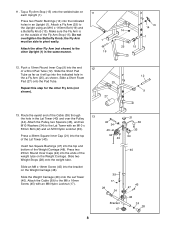
... Fly Arm must be able to the Upright using an M10 x 115mm Bolt (19) and a Butterfly Knob (13). Slide a Short Foam Pad (27) onto the Pad Tube. 25 Repeat this step for the other Upright (1) in an Upright (1). Insert two Square Bushings (47) into the ends of the Weight Carriage (48). Route the eyelet end of the Lat Tower (40). Attach the Pulley...
... Fly Arm must be able to the Upright using an M10 x 115mm Bolt (19) and a Butterfly Knob (13). Slide a Short Foam Pad (27) onto the Pad Tube. 25 Repeat this step for the other Upright (1) in an Upright (1). Insert two Square Bushings (47) into the ends of the Weight Carriage (48). Route the eyelet end of the Lat Tower (40). Attach the Pulley...
User Manual
Page 9
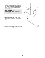
... (38) onto the Lat 38 Bar. 37 38 16. Make sure that all remaining parts will be explained in the Uprights (1). WARNING: Always insert the Weight Rests (51) into the ends of all parts are properly tightened before you use of the Weight Rests (51). 14. Wet the ends of holes in ADJUSTMENTS starting on the next page. 9 Press two 25mm Round...
... (38) onto the Lat 38 Bar. 37 38 16. Make sure that all remaining parts will be explained in the Uprights (1). WARNING: Always insert the Weight Rests (51) into the ends of all parts are properly tightened before you use of the Weight Rests (51). 14. Wet the ends of holes in ADJUSTMENTS starting on the next page. 9 Press two 25mm Round...
User Manual
Page 10
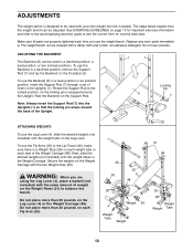
.... ADJUSTMENTS The weight bench is designed to be used with your own weight set of the Upright. 1 1 Locking Pin 6 7 3 ATTACHING WEIGHTS To use the Backrest in a declined position, a level position, or two inclined positions. See EXERCISE GUIDELINES on the Support Rod. ADJUSTING THE BACKREST The Backrest (6) can be adjusted. Rest the Backrest on page 13 for important exercise information and refer to the accompanying exercise guide to see the correct form...
.... ADJUSTMENTS The weight bench is designed to be used with your own weight set of the Upright. 1 1 Locking Pin 6 7 3 ATTACHING WEIGHTS To use the Backrest in a declined position, a level position, or two inclined positions. See EXERCISE GUIDELINES on the Support Rod. ADJUSTING THE BACKREST The Backrest (6) can be adjusted. Rest the Backrest on page 13 for important exercise information and refer to the accompanying exercise guide to see the correct form...
User Manual
Page 11
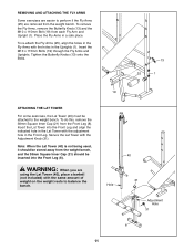
... weight bench. REMOVING AND ATTACHING THE FLY ARMS Some exercises are easier to perform if the Fly Arms (25) are using the Lat Tower (40), place a barbell (not included) with the adjustment hole in the Front Leg. Place the Fly Arms in a safe place. To do this, remove the 38mm Square Inner Cap (21) from each Fly Arm and Upright (1). To remove the Fly Arms, remove the Butterfly Knob...
... weight bench. REMOVING AND ATTACHING THE FLY ARMS Some exercises are easier to perform if the Fly Arms (25) are using the Lat Tower (40), place a barbell (not included) with the adjustment hole in the Front Leg. Place the Fly Arms in a safe place. To do this, remove the 38mm Square Inner Cap (21) from each Fly Arm and Upright (1). To remove the Fly Arms, remove the Butterfly Knob...
User Manual
Page 12
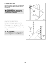
... 41 37 Lat Bar Rest 40 ADJUSTING THE WEIGHT RESTS The Weight Rests (51) can be adjusted to the locked position, with a Cable Clip (41). To move the Weight Rests, disengage the locking pins and remove the Weight Rest from the Uprights (1). WARNING: Always insert the Weight Rests (51) into a set of holes in the Uprights. Rotate the Weight Rests to three heights. ATTACHING THE LAT BAR Attach the Lat Bar (37) to...
... 41 37 Lat Bar Rest 40 ADJUSTING THE WEIGHT RESTS The Weight Rests (51) can be adjusted to the locked position, with a Cable Clip (41). To move the Weight Rests, disengage the locking pins and remove the Weight Rest from the Uprights (1). WARNING: Always insert the Weight Rests (51) into a set of holes in the Uprights. Rotate the Weight Rests to three heights. ATTACHING THE LAT BAR Attach the Lat Bar (37) to...
User Manual
Page 13
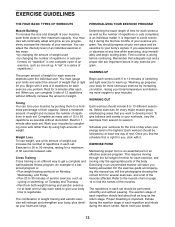
... each exercise depends upon the individual user. To give your workouts, vary the exercises from both weight training and aerobic exercise for each exercise, and moving only the appropriate parts of repetitions in each set. EXERCISE FORM Maintaining proper form is right for a maximum of weight. On the exercise guide accompanying this manual you experience pain or dizziness at least one day of weight training and aerobic exercise will continually adapt and...
... each exercise depends upon the individual user. To give your workouts, vary the exercises from both weight training and aerobic exercise for each exercise, and moving only the appropriate parts of repetitions in each set. EXERCISE FORM Maintaining proper form is right for a maximum of weight. On the exercise guide accompanying this manual you experience pain or dizziness at least one day of weight training and aerobic exercise will continually adapt and...
User Manual
Page 14
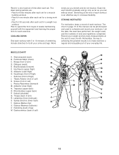
... Maximus (buttocks) V. Rest for both your arms and legs. The ideal resting periods are: • Rest for three minutes after each set for a muscle building workout. • Rest for one minute after each set . STAYING MOTIVATED For motivation, keep a record of thigh) I Q. List the date, the exercises performed, the weight used to increase flexibility. Hip Flexors (upper thigh) G. Tibialis...
... Maximus (buttocks) V. Rest for both your arms and legs. The ideal resting periods are: • Rest for three minutes after each set for a muscle building workout. • Rest for one minute after each set . STAYING MOTIVATED For motivation, keep a record of thigh) I Q. List the date, the exercises performed, the weight used to increase flexibility. Hip Flexors (upper thigh) G. Tibialis...

User Manual
Page 15
MONDAY Date: / / EXERCISE WEIGHT SETS REPS TUESDAY Date: / / AEROBIC EXERCISE WEDNESDAY Date: / / EXERCISE WEIGHT SETS REPS THURSDAY Date: / / AEROBIC EXERCISE FRIDAY Date: / / EXERCISE WEIGHT SETS REPS Make photocopies of this page for scheduling and recording your workouts. 15
MONDAY Date: / / EXERCISE WEIGHT SETS REPS TUESDAY Date: / / AEROBIC EXERCISE WEDNESDAY Date: / / EXERCISE WEIGHT SETS REPS THURSDAY Date: / / AEROBIC EXERCISE FRIDAY Date: / / EXERCISE WEIGHT SETS REPS Make photocopies of this page for scheduling and recording your workouts. 15
User Manual
Page 16
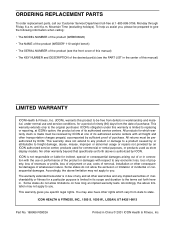
... to give the following information when calling: • The MODEL NUMBER of the product (WEBE03820) • The NAME of the product (WEIDER® 110 weight bench) • The SERIAL NUMBER of the product (see the front cover of this manual) • The KEY NUMBER and DESCRIPTION of the desired part(s) (see the PART LIST in the center of this manual) LIMITED WARRANTY ICON Health & Fitness, Inc. (ICON), warrants this warranty is in lieu of...
... to give the following information when calling: • The MODEL NUMBER of the product (WEBE03820) • The NAME of the product (WEIDER® 110 weight bench) • The SERIAL NUMBER of the product (see the front cover of this manual) • The KEY NUMBER and DESCRIPTION of the desired part(s) (see the PART LIST in the center of this manual) LIMITED WARRANTY ICON Health & Fitness, Inc. (ICON), warrants this warranty is in lieu of...

User Manual
Page 17
REMOVE THIS PART IDENTIFICATION CHART PART LIST/EXPLODED DRAWING SAVE THIS PART IDENTIFICATION CHART PART LIST/EXPLODED DRAWING FOR FUTURE REFERENCE 81
REMOVE THIS PART IDENTIFICATION CHART PART LIST/EXPLODED DRAWING SAVE THIS PART IDENTIFICATION CHART PART LIST/EXPLODED DRAWING FOR FUTURE REFERENCE 81
User Manual
Page 18
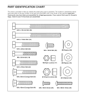
... part refers to the key number of the part from the PART LIST in the parts bags, check to help you cannot find a part in the center of this manual. M10 x 135 mm Bolt (36) M10 x 115mm Bolt (19) M10 x 60mm Bolt (32) M8 x 55mm Bolt (18) M10 x 55mm Bolt (42) M8 x 16mm Bolt ...x 50mm Carriage Bolt (52) M10 Nylon Locknut (33) M10 Washer (34) M8 x 40mm Carriage Bolt (46) M6 x 16mm Screw (29) M6 x 38mm Screw (30) Important: Some parts may have been pre-assembled for shipping purposes. If you identify the small parts used in assembly. PART IDENTIFICATION CHART This chart is provided to...
... part refers to the key number of the part from the PART LIST in the parts bags, check to help you cannot find a part in the center of this manual. M10 x 135 mm Bolt (36) M10 x 115mm Bolt (19) M10 x 60mm Bolt (32) M8 x 55mm Bolt (18) M10 x 55mm Bolt (42) M8 x 16mm Bolt ...x 50mm Carriage Bolt (52) M10 Nylon Locknut (33) M10 Washer (34) M8 x 40mm Carriage Bolt (46) M6 x 16mm Screw (29) M6 x 38mm Screw (30) Important: Some parts may have been pre-assembled for shipping purposes. If you identify the small parts used in assembly. PART IDENTIFICATION CHART This chart is provided to...
User Manual
Page 19
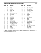
... x 135mm Bolt 37 1 Lat Bar 38 2 Handgrip 39 1 Cable 40 1 Lat Tower 41 1 Cable Clip 42 1 M10 x 55mm Bolt 43 2 Spacer 44 1 Pulley 45 1 M8 x 16mm Screw 46 2 M8 x 40mm Carriage Bolt 47 2 Square Bushing 48 1 Weight Carriage 49 1 Stabilizer 50 2 Weight Clip 51 2 Weight Rest 52 2 M8 x 50mm Carriage Bolt # 1 User's Manual # 1 Exercise Guide # 1 Grease Packet "#" Indicates a non-illustrated part. Qty. Description Key No. Specifications are subject to change without notice. PART LIST-Model No.
... x 135mm Bolt 37 1 Lat Bar 38 2 Handgrip 39 1 Cable 40 1 Lat Tower 41 1 Cable Clip 42 1 M10 x 55mm Bolt 43 2 Spacer 44 1 Pulley 45 1 M8 x 16mm Screw 46 2 M8 x 40mm Carriage Bolt 47 2 Square Bushing 48 1 Weight Carriage 49 1 Stabilizer 50 2 Weight Clip 51 2 Weight Rest 52 2 M8 x 50mm Carriage Bolt # 1 User's Manual # 1 Exercise Guide # 1 Grease Packet "#" Indicates a non-illustrated part. Qty. Description Key No. Specifications are subject to change without notice. PART LIST-Model No.

User Manual
Page 20
WEBE03820 R0902A 38 9 7 42 21 37 34 34 33 39 41 43 9 51 24 38 44 43 12 1 22 9 16 40 27 17 25 28 24 16 14 15 21 35 6 26 5 30 21 5 36 34 14 13 35 34 33 18 21 3 26 30 24 51 18 1 13 14 39 17 28 24 50 19 46 22 21 47 45 8 48 17 24 21 47 28 52 23 9 16 29 17 31 17 49 21 52 10 9 21 18 2 17 19 25 29 18 16 14 17 12 16 15 9 22 21 24 28 27 22 11 23 32 4 33 22 20 9 10 24 22 9 23 23 EXPLODED DRAWING-Model No.
WEBE03820 R0902A 38 9 7 42 21 37 34 34 33 39 41 43 9 51 24 38 44 43 12 1 22 9 16 40 27 17 25 28 24 16 14 15 21 35 6 26 5 30 21 5 36 34 14 13 35 34 33 18 21 3 26 30 24 51 18 1 13 14 39 17 28 24 50 19 46 22 21 47 45 8 48 17 24 21 47 28 52 23 9 16 29 17 31 17 49 21 52 10 9 21 18 2 17 19 25 29 18 16 14 17 12 16 15 9 22 21 24 28 27 22 11 23 32 4 33 22 20 9 10 24 22 9 23 23 EXPLODED DRAWING-Model No.


