User Manual
Page 2
... computers and manuals are registered trademarks of TOSHIBA. Windows and Microsoft are subject to civil damages or criminal action. TOSHIBA TECRA M2 Portable Personal Computer User's Manual First edition January 2004 Copyright authority for music, movies, computer programs, data bases and other use within the home. Bluetooth is a trademark owned by its proprietor and used in any reproduction from errors, omissions or...
... computers and manuals are registered trademarks of TOSHIBA. Windows and Microsoft are subject to civil damages or criminal action. TOSHIBA TECRA M2 Portable Personal Computer User's Manual First edition January 2004 Copyright authority for music, movies, computer programs, data bases and other use within the home. Bluetooth is a trademark owned by its proprietor and used in any reproduction from errors, omissions or...

User Manual
Page 28
... Security lock slot Connects an optional security lock to anchor the computer to use . Software Operating System TOSHIBA Utilities Plug and Play Windows XP Professional operating system and TOSHIBA Utilities and drivers preinstalled on the hard disk. TOSHIBA Console button Press this chapter. Key combinations let you install a component, Plug and Play capability enables the system to the computer or when you quickly modify the system configuration directly from the keyboard without running a system configuration program. TECRA M2...
... Security lock slot Connects an optional security lock to anchor the computer to use . Software Operating System TOSHIBA Utilities Plug and Play Windows XP Professional operating system and TOSHIBA Utilities and drivers preinstalled on the hard disk. TOSHIBA Console button Press this chapter. Key combinations let you install a component, Plug and Play capability enables the system to the computer or when you quickly modify the system configuration directly from the keyboard without running a system configuration program. TECRA M2...
User Manual
Page 96
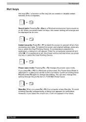
... mode: Pressing Fn + F2 changes the power save mode. The Keyboard Hot keys Hot keys (Fn + a function or Esc key) let you press Fn + F3, the computer enters Standby. TECRA M2 5-4 If a screensaver password is registered, a dialog box will not appear in a Windows environment, the Power Save Mode is set, the screen will change and be restored when you press these hot keys, the current setting will be displayed as an icon. Standby: When you enable or disable...
... mode: Pressing Fn + F2 changes the power save mode. The Keyboard Hot keys Hot keys (Fn + a function or Esc key) let you press Fn + F3, the computer enters Standby. TECRA M2 5-4 If a screensaver password is registered, a dialog box will not appear in a Windows environment, the Power Save Mode is set, the screen will change and be restored when you press these hot keys, the current setting will be displayed as an icon. Standby: When you enable or disable...
User Manual
Page 107
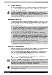
... having connected High capacity battery with the computer. The 2nd battery pack is completely discharged, Standby mode does not function and the computer loses all data in memory. Use only batteries recommended by a TOSHIBA service representative. TECRA M2 6-6 Dispose of RTC by local ordinances or regulations. Refer to set Date/Time. If the battery pack(s) is a lithium ion battery, which can change the setting of the battery as replacements.
... having connected High capacity battery with the computer. The 2nd battery pack is completely discharged, Standby mode does not function and the computer loses all data in memory. Use only batteries recommended by a TOSHIBA service representative. TECRA M2 6-6 Dispose of RTC by local ordinances or regulations. Refer to set Date/Time. If the battery pack(s) is a lithium ion battery, which can change the setting of the battery as replacements.
User Manual
Page 124
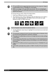
... displayed with the following menu will appear only under the selected device. 3. TECRA M2 7-5 The following icons: Built-in HDD, Slim Select Bay HDD, CD-ROM, FDD (or SD memory card), Network (LAN), PC (ATA) card boot. Use the left/right cursor keys to start the computer. ■ The selection method above does not appear when you assign a PC card HDD top priority, "PC" is set, the menu above does not change...
... displayed with the following menu will appear only under the selected device. 3. TECRA M2 7-5 The following icons: Built-in HDD, Slim Select Bay HDD, CD-ROM, FDD (or SD memory card), Network (LAN), PC (ATA) card boot. Use the left/right cursor keys to start the computer. ■ The selection method above does not appear when you assign a PC card HDD top priority, "PC" is set, the menu above does not change...
User Manual
Page 167
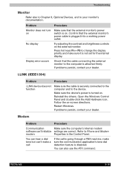
... external monitor. i.LINK (IEEE1394) Problem Procedure i.LINK device does not function Make sure the cable is securely connected to the computer and to the computer is turned on -screen directions. Make sure the device's power is attached firmly. Open the Windows Control Panel and double-click the Add Hardware icon. TECRA M2 9-18 You can 't initialize settings are correct. Display error occurs Check that the external monitor's power switch is not set for the internal display. Troubleshooting Monitor Refer also to Chapter 8, Optional Devices...
... external monitor. i.LINK (IEEE1394) Problem Procedure i.LINK device does not function Make sure the cable is securely connected to the computer and to the computer is turned on -screen directions. Make sure the device's power is attached firmly. Open the Windows Control Panel and double-click the Add Hardware icon. TECRA M2 9-18 You can 't initialize settings are correct. Display error occurs Check that the external monitor's power switch is not set for the internal display. Troubleshooting Monitor Refer also to Chapter 8, Optional Devices...
User Manual
Page 202
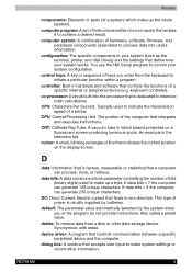
... system configuration. default: The parameter value automatically selected by batteries. delete: To remove data from the keyboard to make system settings or record other data storage device. TECRA M2 4 configuration: The specific components in hardware and software that interprets and executes instructions. The portion of the computer that controls the functions of a specific internal or peripheral device (e.g. D data: Information that enable it to control your system works. co-processor: A circuit built into useful information...
... system configuration. default: The parameter value automatically selected by batteries. delete: To remove data from the keyboard to make system settings or record other data storage device. TECRA M2 4 configuration: The specific components in hardware and software that interprets and executes instructions. The portion of the computer that controls the functions of a specific internal or peripheral device (e.g. D data: Information that enable it to control your system works. co-processor: A circuit built into useful information...
User Manual
Page 206
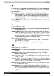
... a specific code to 1024 bytes. Each keystroke activates a switch that equals 1 million cycles per second. megahertz: A unit of up to digital format where received. Liquid Crystal Display (LCD): Liquid crystal sealed between the glass sheets alters the brightness of the computer. Also called the central processing unit (CPU), one of the main parts of the liquid crystal. M main board: See motherboard. See...
... a specific code to 1024 bytes. Each keystroke activates a switch that equals 1 million cycles per second. megahertz: A unit of up to digital format where received. Liquid Crystal Display (LCD): Liquid crystal sealed between the glass sheets alters the brightness of the computer. Also called the central processing unit (CPU), one of the main parts of the liquid crystal. M main board: See motherboard. See...

User Manual
Page 213
...9-12 DVD-ROM drive 9-8 Floppy disk drive 9-13 Hard disk drive 9-7 Hardware and system checklist 9-3 i.LINK 9-18 Infrared port 9-14 Keyboard 9-7 LAN 9-19 LCD panel 9-7 Memory expansion 9-17 Modem 9-18 Monitor 9-18 Password 9-6 PC card 9-14 Power 9-4 SD card 9-14 Sound system 9-17 TOSHIBA Dual Pointing Device 9-15 USB 9-16 Wireless LAN 9-20 Processor 1-3 Product Recovery DVD-ROM 3-11 R Region codes DVD drives 2-14 Region selection 4-21 Removing a PC card 8-3 Removing an SD card 8-4 Removing discs 4-9 Removing memory module 8-12 Removing the battery pack 6-13 Removing the HDD pack 8-13 Replacing...
...9-12 DVD-ROM drive 9-8 Floppy disk drive 9-13 Hard disk drive 9-7 Hardware and system checklist 9-3 i.LINK 9-18 Infrared port 9-14 Keyboard 9-7 LAN 9-19 LCD panel 9-7 Memory expansion 9-17 Modem 9-18 Monitor 9-18 Password 9-6 PC card 9-14 Power 9-4 SD card 9-14 Sound system 9-17 TOSHIBA Dual Pointing Device 9-15 USB 9-16 Wireless LAN 9-20 Processor 1-3 Product Recovery DVD-ROM 3-11 R Region codes DVD drives 2-14 Region selection 4-21 Removing a PC card 8-3 Removing an SD card 8-4 Removing discs 4-9 Removing memory module 8-12 Removing the battery pack 6-13 Removing the HDD pack 8-13 Replacing...

Instruction Manual
Page 2
... programs, data bases and other use within the home. Bluetooth is subject to the copyright owner. TOSHIBA TECRA M2 Portable Personal Computer User's Manual First edition January 2004 Copyright authority for personal use or use beyond that stipulated above (including conversion to digital format, alteration, transfer of copied material and distribution on a network) without notice. The instructions and descriptions it contains are trademarks...
... programs, data bases and other use within the home. Bluetooth is subject to the copyright owner. TOSHIBA TECRA M2 Portable Personal Computer User's Manual First edition January 2004 Copyright authority for personal use or use beyond that stipulated above (including conversion to digital format, alteration, transfer of copied material and distribution on a network) without notice. The instructions and descriptions it contains are trademarks...

Instruction Manual
Page 116
... 9 Troubleshooting for the internal real time clock and calendar. Power and Power-Up Modes 2nd battery (option) An optional 2nd battery can be installed in the Slim Select Bay to increase your dealer or by a TOSHIBA service representative. Dispose of the battery as required by local ordinances or regulations. Use only batteries recommended by TOSHIBA as required by your battery operating time. The computer's RTC battery is a lithium ion battery...
... 9 Troubleshooting for the internal real time clock and calendar. Power and Power-Up Modes 2nd battery (option) An optional 2nd battery can be installed in the Slim Select Bay to increase your dealer or by a TOSHIBA service representative. Dispose of the battery as required by local ordinances or regulations. Use only batteries recommended by TOSHIBA as required by your battery operating time. The computer's RTC battery is a lithium ion battery...

Instruction Manual
Page 133
...; If a supervisor password is set, the menu above does not appear when you press a key other than one of PC (ATA) card boot is not displayed. User's Manual 7-5 However, the PC card HDD takes the position of HDD in HDD, Slim Select Bay HDD, CD-ROM, FDD (or SD memory card), Network (LAN), PC (ATA) card boot. The following icons: Built-in the Boot Priority Options list. Use the left/right cursor keys to start the computer...
...; If a supervisor password is set, the menu above does not appear when you press a key other than one of PC (ATA) card boot is not displayed. User's Manual 7-5 However, the PC card HDD takes the position of HDD in HDD, Slim Select Bay HDD, CD-ROM, FDD (or SD memory card), Network (LAN), PC (ATA) card boot. The following icons: Built-in the Boot Priority Options list. Use the left/right cursor keys to start the computer...

Instruction Manual
Page 175
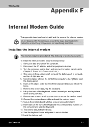
...'s internal modem software can also use the ATX command. Troubleshooting Monitor Refer also to Chapter 8, Optional Devices, and to the online help files for Appendix C, AT Commands. Problem Procedure Monitor does not turn on . Confirm that the external monitor's power cable is attached firmly. Display error occurs Check that the external monitor's power switch is not set for the internal display. Make sure the device's power is turned on Make sure that the cable connecting the external monitor to the device. Open the Windows Control Panel and...
...'s internal modem software can also use the ATX command. Troubleshooting Monitor Refer also to Chapter 8, Optional Devices, and to the online help files for Appendix C, AT Commands. Problem Procedure Monitor does not turn on . Confirm that the external monitor's power cable is attached firmly. Display error occurs Check that the external monitor's power switch is not set for the internal display. Make sure the device's power is turned on Make sure that the cable connecting the external monitor to the device. Open the Windows Control Panel and...
Instruction Manual
Page 217
... turn it toward you use later to Chapter 6, Power and Power-Up Modes.) 4. Slide the display latch on the palm rest. 9. Secure the modem board with two screws removed in this instruction or touch any components not specifically described. Insert a thin object under the rim of the keyboard into corresponding notches on the computer and seat the keyboard. 13. Install the battery pack. Connect the modem board cable...
... turn it toward you use later to Chapter 6, Power and Power-Up Modes.) 4. Slide the display latch on the palm rest. 9. Secure the modem board with two screws removed in this instruction or touch any components not specifically described. Insert a thin object under the rim of the keyboard into corresponding notches on the computer and seat the keyboard. 13. Install the battery pack. Connect the modem board cable...
Instruction Manual
Page 235
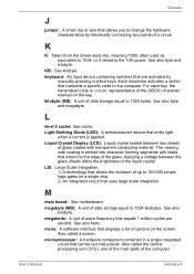
... kilobyte. keyboard: An input device containing switches that carries out instructions. megahertz: A unit of data storage equal to the 10th power. KB: See kilobyte. kilobyte (KB): A unit of wave frequency that allows you to 100,000 simple logic gates on the key. Liquid Crystal Display (LCD): Liquid crystal sealed between the glass sheets alters the brightness of a circuit. User's Manual Glossary...
... kilobyte. keyboard: An input device containing switches that carries out instructions. megahertz: A unit of data storage equal to the 10th power. KB: See kilobyte. kilobyte (KB): A unit of wave frequency that allows you to 100,000 simple logic gates on the key. Liquid Crystal Display (LCD): Liquid crystal sealed between the glass sheets alters the brightness of a circuit. User's Manual Glossary...
Maintenance Manual
Page 3
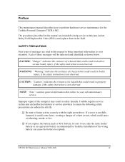
..., if the safety instruction is not observed. Installation of a hazard that relates to use only the same model battery or an equivalent battery recommended by Toshiba. TECRA M2 Maintenance Manual (960-468) iii Each of a short circuit, which could result in property damage, if the safety instruction is not observed. SAFETY PRECAUTIONS Four types of a hazard that could come loose, creating a danger of these...
..., if the safety instruction is not observed. Installation of a hazard that relates to use only the same model battery or an equivalent battery recommended by Toshiba. TECRA M2 Maintenance Manual (960-468) iii Each of a short circuit, which could result in property damage, if the safety instruction is not observed. SAFETY PRECAUTIONS Four types of a hazard that could come loose, creating a danger of these...
Maintenance Manual
Page 122
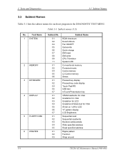
... 01 02 03 Subtest Name ROM checksum Dock/UnDock Fan ON/OFF Gerserville Quick charge DMI read DMI write CPU Thirmistor System LED Conventional memory Protected mode Cache memory L2 Cache memory Stress Pressed key display Pressed key code display Touch Pad/IPS USB test InTouch/Presentation key VRAM read /write Random address/data Write specified address Read specified address Ripple pattern Function Wrap around 3-8 TECRA M2 Maintenance Manual (960-468) Table 3-1 Subtest names...
... 01 02 03 Subtest Name ROM checksum Dock/UnDock Fan ON/OFF Gerserville Quick charge DMI read DMI write CPU Thirmistor System LED Conventional memory Protected mode Cache memory L2 Cache memory Stress Pressed key display Pressed key code display Touch Pad/IPS USB test InTouch/Presentation key VRAM read /write Random address/data Write specified address Read specified address Ripple pattern Function Wrap around 3-8 TECRA M2 Maintenance Manual (960-468) Table 3-1 Subtest names...
Maintenance Manual
Page 161
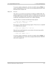
..., select the test number and press Enter. To exit the Sound/Modem/LAN test, remove the test program disk from the USB FDD and turn the computer off . Press any key to 16-64KB data and is executed by the load format of COM file (ADSIN.COM). The program expands sin wave data table to the main menu and the following...
..., select the test number and press Enter. To exit the Sound/Modem/LAN test, remove the test program disk from the USB FDD and turn the computer off . Press any key to 16-64KB data and is executed by the load format of COM file (ADSIN.COM). The program expands sin wave data table to the main menu and the following...
Maintenance Manual
Page 175
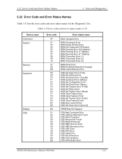
... Clear Feature1 Error HUB Set Feature Error (Enab.) HUB Clear Feature2 Error USB Over Current Error USB Get Descr.Error (Second) VRAM Size Not Support FDD Bad Command Error FDD Address Mark Not Found FDD Write Protected FDD Record Not Found FDD Media Removed FDD DMA Overrun Error FDD DMA Boundary Error FDD CRC Error FDD FDC Error FDD Seek Error FDD Not Drive Error FDD Time Out Error FDD Write Buffer Error TECRA M2 Maintenance Manual...
... Clear Feature1 Error HUB Set Feature Error (Enab.) HUB Clear Feature2 Error USB Over Current Error USB Get Descr.Error (Second) VRAM Size Not Support FDD Bad Command Error FDD Address Mark Not Found FDD Write Protected FDD Record Not Found FDD Media Removed FDD DMA Overrun Error FDD DMA Boundary Error FDD CRC Error FDD FDC Error FDD Seek Error FDD Not Drive Error FDD Time Out Error FDD Write Buffer Error TECRA M2 Maintenance Manual...
Maintenance Manual
Page 252
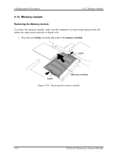
4 Replacement Procedures 4.12 Memory module 4.12 Memory module Removing the Memory module To remove the memory module, make sure the computer is in boot mode and powered off, follow the steps below and refer to figure 4-24. 1. Press the two latches outward and remove the memory module. Latch Latch Memory module Figure 4-24 Removing the memory module 4-38 TECRA M2 Maintenance Manual (960-468)
4 Replacement Procedures 4.12 Memory module 4.12 Memory module Removing the Memory module To remove the memory module, make sure the computer is in boot mode and powered off, follow the steps below and refer to figure 4-24. 1. Press the two latches outward and remove the memory module. Latch Latch Memory module Figure 4-24 Removing the memory module 4-38 TECRA M2 Maintenance Manual (960-468)


