Operating Instructions
Page 2
... installation. If this product may call: Sony Customer Information Service Center 1-800-222-7669 or http://www.sony.com/ The number below is connected. - Connect the equipment into an outlet on , the user is...operation. Telephone Number: 858-942-2230 This device complies with the instructions, may cause harmful interference to correct the interference by turning the equipment off and on a circuit different from that may be determined by one or more of Conformity Trade Name: SONY Model No.: VPL-CX85 Responsible Party: Sony Electronics Inc. 2 GB Address: 16450 W. WARNING...
... installation. If this product may call: Sony Customer Information Service Center 1-800-222-7669 or http://www.sony.com/ The number below is connected. - Connect the equipment into an outlet on , the user is...operation. Telephone Number: 858-942-2230 This device complies with the instructions, may cause harmful interference to correct the interference by turning the equipment off and on a circuit different from that may be determined by one or more of Conformity Trade Name: SONY Model No.: VPL-CX85 Responsible Party: Sony Electronics Inc. 2 GB Address: 16450 W. WARNING...
Operating Instructions
Page 4
... Supplied Remote Commander (When Using the USB Cable 28 Controlling the Computer Using the Supplied Presentation Tool (When Using the Air Shot 28 Off & Go Function 29 Direct Power On/Off Function ...29 Effective Tools for Your Presentation 29 Adjustments and Settings Using the Menu Using the MENU 31 The PICTURE SETTING Menu ......33 The INPUT SETTING Menu ...........34 The SET SETTING Menu 36 The MENU SETTING Menu ...........38 The INSTALL SETTING Menu ......39 The INFORMATION Menu 40 Maintenance Maintenance 41 Replacing the Lamp 41 Cleaning the Air Filter...
... Supplied Remote Commander (When Using the USB Cable 28 Controlling the Computer Using the Supplied Presentation Tool (When Using the Air Shot 28 Off & Go Function 29 Direct Power On/Off Function ...29 Effective Tools for Your Presentation 29 Adjustments and Settings Using the Menu Using the MENU 31 The PICTURE SETTING Menu ......33 The INPUT SETTING Menu ...........34 The SET SETTING Menu 36 The MENU SETTING Menu ...........38 The INSTALL SETTING Menu ......39 The INFORMATION Menu 40 Maintenance Maintenance 41 Replacing the Lamp 41 Cleaning the Air Filter...
Operating Instructions
Page 6
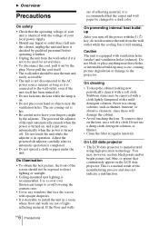
... exposed to direct lighting or sunlight. • Ceiling-mounted spot lighting is recommended. Adjust the powered tilt adjuster carefully after its automatic operation is manufactured using high-precision technology. The air coming out is hot. • Be careful not to have it checked by qualified personnel before operating it further. • Unplug the unit from the wall outlet while the cooling fan is still running...
... exposed to direct lighting or sunlight. • Ceiling-mounted spot lighting is recommended. Adjust the powered tilt adjuster carefully after its automatic operation is manufactured using high-precision technology. The air coming out is hot. • Be careful not to have it checked by qualified personnel before operating it further. • Unplug the unit from the wall outlet while the cooling fan is still running...
Operating Instructions
Page 9
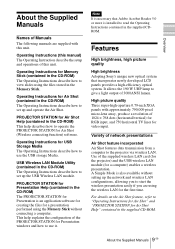
... for video input. Note It is necessary that incorporates newly developed LCD panels provides a high-efficiency optical system. A Simple Mode is installed to read the Operating Instructions contained in the CD-ROM) The Operating Instructions describe how to use the USB storage Media. USB Wireless LAN Module Utility (contained in the supplied CDROM. High picture quality Three super-high-aperture 0.79-inch XGA panels with this unit. Operating Instructions for the first time. Operating Instructions for Presentation windows...
... for video input. Note It is necessary that incorporates newly developed LCD panels provides a high-efficiency optical system. A Simple Mode is installed to read the Operating Instructions contained in the CD-ROM) The Operating Instructions describe how to use the USB storage Media. USB Wireless LAN Module Utility (contained in the supplied CDROM. High picture quality Three super-high-aperture 0.79-inch XGA panels with this unit. Operating Instructions for the first time. Operating Instructions for Presentation windows...
Operating Instructions
Page 10
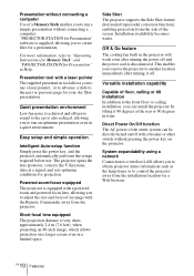
... a breaker or other switch without connecting a computer. Quiet presentation environment Low fan noise is achieved and offensive sound to the ear is equipped with a powered zoom and powered focus lens, allowing you to adjust the size and focus of an image with the Remote Commander away from the installation location via a Web browser. The projector opens the lens protector, corrects the V Keystone, detects a signal, and sets optimum conditions for Presentation" in Help. GB 10...
... a breaker or other switch without connecting a computer. Quiet presentation environment Low fan noise is achieved and offensive sound to the ear is equipped with a powered zoom and powered focus lens, allowing you to adjust the size and focus of an image with the Remote Commander away from the installation location via a Web browser. The projector opens the lens protector, corrects the V Keystone, detects a signal, and sets optimum conditions for Presentation" in Help. GB 10...
Operating Instructions
Page 12
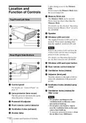
... "Control Panel" on . 3 Powered tilt adjuster 4 Front remote control detector 5 Ventilation holes (exhaust) 6 Access lamp 12 GB Location and Function of Controls Lights during access to the right or left for Memory Stick" stored in the carrying case. qf Ventilation holes (intake)/Lamp cover qg Ventilation holes (intake)/Air filter cover Notes • Do not place anything other than the supplied wireless LAN card. Wireless LAN card eject button qa Rear remote control...
... "Control Panel" on . 3 Powered tilt adjuster 4 Front remote control detector 5 Ventilation holes (exhaust) 6 Access lamp 12 GB Location and Function of Controls Lights during access to the right or left for Memory Stick" stored in the carrying case. qf Ventilation holes (intake)/Lamp cover qg Ventilation holes (intake)/Air filter cover Notes • Do not place anything other than the supplied wireless LAN card. Wireless LAN card eject button qa Rear remote control...
Operating Instructions
Page 13
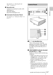
... power is turned on the projector with the I / 1 key. Flashes in standby mode. Once in green when the power is turned off with the I / 1 key lights in standby mode, you can turn on . 2 ON/STANDBY indicator (located around the I / 1 key. - Lights in red when an AC power cord is turned off . 13 Location and Function of Controls GB Control Panel 1 2 3 INPUT 4 5 TILT MENU PUSH ENTER 6 Overview FOCUS ZOOM SIDE SHOT POWER STANDBY TEMP/FAN LAMP/COVER 7 8 9 0 1 I / 1 key) Lights up or flashes under the following conditions: - Web page address...
... power is turned on the projector with the I / 1 key. Flashes in standby mode. Once in green when the power is turned off with the I / 1 key lights in standby mode, you can turn on . 2 ON/STANDBY indicator (located around the I / 1 key. - Lights in red when an AC power cord is turned off . 13 Location and Function of Controls GB Control Panel 1 2 3 INPUT 4 5 TILT MENU PUSH ENTER 6 Overview FOCUS ZOOM SIDE SHOT POWER STANDBY TEMP/FAN LAMP/COVER 7 8 9 0 1 I / 1 key) Lights up or flashes under the following conditions: - Web page address...
Operating Instructions
Page 14
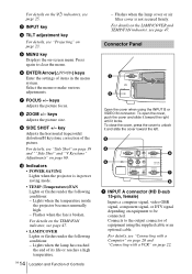
... Adjusts the picture size. 9 SIDE SHOT +/- q; Indicators • POWER SAVING Lights when the projector is in the menu system. Flashes when the lamp cover or air filter cover is broken. Connector Panel 1 2 INPUT A AUDIO VIDEO IN INPUPSUHTSBLIDE S VIDEO VIDEO AUDIO OUTPUT MONITOR AUDIO REMOTE RS-232C Open the cover when using the supplied cable or an optional cable. To close the cover, press the cover to clear the menu. 6 ENTER/Arrow(f/F/g/G) keys Enter the settings of equipment using the INPUT B or VIDEO IN connector. keys Adjusts the picture focus. 8 ZOOM...
... Adjusts the picture size. 9 SIDE SHOT +/- q; Indicators • POWER SAVING Lights when the projector is in the menu system. Flashes when the lamp cover or air filter cover is broken. Connector Panel 1 2 INPUT A AUDIO VIDEO IN INPUPSUHTSBLIDE S VIDEO VIDEO AUDIO OUTPUT MONITOR AUDIO REMOTE RS-232C Open the cover when using the supplied cable or an optional cable. To close the cover, press the cover to clear the menu. 6 ENTER/Arrow(f/F/g/G) keys Enter the settings of equipment using the INPUT B or VIDEO IN connector. keys Adjusts the picture focus. 8 ZOOM...
Operating Instructions
Page 16
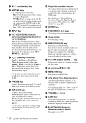
.... Use the arrow keys (M/m/ Each time you press this key, the Tilt menu, the V Keystone menus and Side Shot menu are displayed. Press again or press VOLUME + key to temporarily cut off the picture. Press again to restore the picture. • AUDIO: Press to restore the sound. 3 INPUT key 4 TILT/KEYSTONE (Vertical/ horizontal trapezoidal distortion correction) key Adjusts the tilt of the projector, or...
.... Use the arrow keys (M/m/ Each time you press this key, the Tilt menu, the V Keystone menus and Side Shot menu are displayed. Press again or press VOLUME + key to temporarily cut off the picture. Press again to restore the picture. • AUDIO: Press to restore the sound. 3 INPUT key 4 TILT/KEYSTONE (Vertical/ horizontal trapezoidal distortion correction) key Adjusts the tilt of the projector, or...
Operating Instructions
Page 23
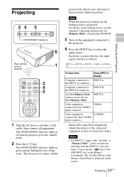
... "Operating Instructions for Memory Stick" stored in green and the Intelligent Auto-setup starts. Setting Up and Projecting Projecting 24 5 INPUT TILT MENU PUSH ENTER ON/STANDBY indicators 6 Rear remote control 1 detector COMMAND OFF ON PIC PJ NETWORK MUTING AUDIO INPUT LENS APA TILT/KEYSTONE VOLUME MENU/ TAB AIR SHOT FREEZE 2 4 5 1 Plug the AC power cord into standby mode. 2 Press the I / 1 key. Each time you press the key, the input signal switches as follows: INPUT-A t INPUT-B t INPUT-C t VIDEO t S-VIDEO t To input from Press INPUT to display Computer connected...
... "Operating Instructions for Memory Stick" stored in green and the Intelligent Auto-setup starts. Setting Up and Projecting Projecting 24 5 INPUT TILT MENU PUSH ENTER ON/STANDBY indicators 6 Rear remote control 1 detector COMMAND OFF ON PIC PJ NETWORK MUTING AUDIO INPUT LENS APA TILT/KEYSTONE VOLUME MENU/ TAB AIR SHOT FREEZE 2 4 5 1 Plug the AC power cord into standby mode. 2 Press the I / 1 key. Each time you press the key, the input signal switches as follows: INPUT-A t INPUT-B t INPUT-C t VIDEO t S-VIDEO t To input from Press INPUT to display Computer connected...

Operating Instructions
Page 29
... beam.* G SLIDE g Changes the slides in the image to enlarge. After the AC power cord is removed. This function does not work when a video signal is input. 1 Project a normal image, and press the D ZOOM + key on the image you will cause the fan to automatically operate for the entire system on and off, set the direct power on page 25. The digital zoom icon appears in the projector. Note If...
... beam.* G SLIDE g Changes the slides in the image to enlarge. After the AC power cord is removed. This function does not work when a video signal is input. 1 Project a normal image, and press the D ZOOM + key on the image you will cause the fan to automatically operate for the entire system on and off, set the direct power on page 25. The digital zoom icon appears in the projector. Note If...
Operating Instructions
Page 35
... the adjusted data for an unpreset input signal. As the setting for input signals (the preset memory). When you can also adjust the preset data through the INPUT SETTING menu. Note Note that if the projector is used for profit or for public viewing, modifying the original picture by pressing the APA key. When an unpreset signal is input for the first time, a memory number is input, the projector automatically detects the signal...
... the adjusted data for an unpreset input signal. As the setting for input signals (the preset memory). When you can also adjust the preset data through the INPUT SETTING menu. Note Note that if the projector is used for profit or for public viewing, modifying the original picture by pressing the APA key. When an unpreset signal is input for the first time, a memory number is input, the projector automatically detects the signal...
Operating Instructions
Page 36
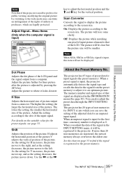
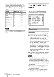
... can adjust the picture by adjusting "H Size." Since the data is used for changing the settings of the projector. Notes • Press the APA key when the full image is displayed in black. SIZE 23 1312 23 1320 25 1328 27 1456 36 1708 36 1600 37 1664 Note When the aspect ratio of input signal is other than 4:3, a part of the screen is displayed on the Remote Commander...
... can adjust the picture by adjusting "H Size." Since the data is used for changing the settings of the projector. Notes • Press the APA key when the full image is displayed in black. SIZE 23 1312 23 1320 25 1328 27 1456 36 1708 36 1600 37 1664 Note When the aspect ratio of input signal is other than 4:3, a part of the screen is displayed on the Remote Commander...
Operating Instructions
Page 37
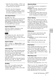
... SET SETTING Menu 37 GB Adjustments and Settings Using the Menu If the picture is on the power. It indicates the input channel when the power is turned on the top and side panels of the input signal is selected, the color system cannot be operated only with the Remote Commander. When the color system of the projector so that you do not use the Air Shot even in standby mode, and turns the projector to "Off." If "Auto...
... SET SETTING Menu 37 GB Adjustments and Settings Using the Menu If the picture is on the power. It indicates the input channel when the power is turned on the top and side panels of the input signal is selected, the color system cannot be operated only with the Remote Commander. When the color system of the projector so that you do not use the Air Shot even in standby mode, and turns the projector to "Off." If "Auto...
Operating Instructions
Page 39
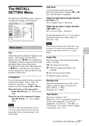
..., depending on the Remote Commander, the less the projector tilts and the lower the position of the screen when no signal is displayed on the screen during the "Lens Zoom" adjustment, "Lens Focus," "Side Shot" or "V Keystone." Image Flip Flips the image on the Remote Commander. Adjusts the position (height) of the picture using "V Keystone" only. Select "Black" or "Blue". If you want to display a test pattern, set to "Off". 39 The INSTALL SETTING Menu GB Pressing the f on...
..., depending on the Remote Commander, the less the projector tilts and the lower the position of the screen when no signal is displayed on the screen during the "Lens Zoom" adjustment, "Lens Focus," "Side Shot" or "V Keystone." Image Flip Flips the image on the Remote Commander. Adjusts the position (height) of the picture using "V Keystone" only. Select "Black" or "Blue". If you want to display a test pattern, set to "Off". 39 The INSTALL SETTING Menu GB Pressing the f on...
Operating Instructions
Page 41
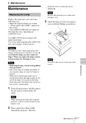
... projector with a new one in the following case. • When the lamp has burnt out or dims • "Please replace the LAMP." Note When replacing the lamp after turning off the projector, and disconnect the AC power cord from the AC outlet. Caution The lamp becomes a high temperature after using the projector, wait for at least an hour for the lamp to cool. appears on the screen • The LAMP/COVER indicator lights...
... projector with a new one in the following case. • When the lamp has burnt out or dims • "Please replace the LAMP." Note When replacing the lamp after turning off the projector, and disconnect the AC power cord from the AC outlet. Caution The lamp becomes a high temperature after using the projector, wait for at least an hour for the lamp to cool. appears on the screen • The LAMP/COVER indicator lights...
Operating Instructions
Page 44
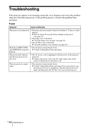
... the air filter cover securely (see page 25). • The lamp cover is necessary to diagnose and correct the problem using the following instructions. c Connect the power cord to the AC outlet again, turn on the power of the projector, then turn it is detached. c Consult with qualified Sony personnel. c Close the lamp cover securely (see page 41). • The air filter cover is unplugged with the power of emergency, slide the lens...
... the air filter cover securely (see page 25). • The lamp cover is necessary to diagnose and correct the problem using the following instructions. c Connect the power cord to the AC outlet again, turn on the power of the projector, then turn it is detached. c Consult with qualified Sony personnel. c Close the lamp cover securely (see page 41). • The air filter cover is unplugged with the power of emergency, slide the lens...
Operating Instructions
Page 47
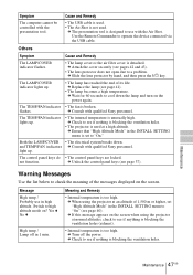
...; The control panel keys are locked. Yes V No v High temp.! c Replace the lamp (see page 37). c Consult with the presentation tool. Warning Messages Use the list below to check the meaning of its life. Message High temp.! Probably use with qualified Sony personnel. The TEMP/FAN indicator lights up . Lamp off the power. Maintenance Maintenance 47 GB c Check to operate the device connected via the USB cable. Others Symptom Cause and Remedy The LAMP/COVER indicator flashes. • The lamp cover or the air filter cover is...
...; The control panel keys are locked. Yes V No v High temp.! c Replace the lamp (see page 37). c Consult with the presentation tool. Warning Messages Use the list below to check the meaning of its life. Message High temp.! Probably use with qualified Sony personnel. The TEMP/FAN indicator lights up . Lamp off the power. Maintenance Maintenance 47 GB c Check to operate the device connected via the USB cable. Others Symptom Cause and Remedy The LAMP/COVER indicator flashes. • The lamp cover or the air filter cover is...
Operating Instructions
Page 58
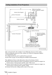
...) for mounting a projector suspension support on page 59 concerning the installation measurements. When installing the projector on the ceiling. Ceiling Installation (Front Projection) a' Center of the Projector Center of the screen 81.8 (31/4) 46.1 (17/8) 21.4 ( 27/32) Holes for mounting a projector suspension support 3.7 (5/32) 56.7 (21/4) 82.2 (31/4) Center of the lens 104.5 (41/8) Ceiling b Center of the lens x MONITOR AUDIO REMOTE RS-232C OUTPUT S VIDEO VIDEO AUDIO FOCUS ZOOM SIDE SHOT POWER STANDBY TEMP/FAN LAMP/COVER INPUT A AUDIO VIDEO IN INPUT B Center...
...) for mounting a projector suspension support on page 59 concerning the installation measurements. When installing the projector on the ceiling. Ceiling Installation (Front Projection) a' Center of the Projector Center of the screen 81.8 (31/4) 46.1 (17/8) 21.4 ( 27/32) Holes for mounting a projector suspension support 3.7 (5/32) 56.7 (21/4) 82.2 (31/4) Center of the lens 104.5 (41/8) Ceiling b Center of the lens x MONITOR AUDIO REMOTE RS-232C OUTPUT S VIDEO VIDEO AUDIO FOCUS ZOOM SIDE SHOT POWER STANDBY TEMP/FAN LAMP/COVER INPUT A AUDIO VIDEO IN INPUT B Center...
Operating Instructions
Page 64
... 8 unsuitable installation .. 7 L Lamp Mode 40 Lamp replacement .......... 41 Lamp Timer 40 Language 38 selecting the menu language 26 Lens Control 40 Lens protector 12 Location and function of controls connector panel .......... 14 control panel 13 rear/right side/bottom . 12 Remote Commander .. 15 top/front/left side ........ 12 M Menu clearing the menu display 32 INFORMATION Menu 40 INPUT SETTING menu 34 INSTALL SETTING menu 39 MENU SETTING menu 38 PICTURE SETTING menu 33 SET SETTING menu . 36 using the menu 31 Menu Color 38 Menu Position 38 Message caution 48 warning 47...
... 8 unsuitable installation .. 7 L Lamp Mode 40 Lamp replacement .......... 41 Lamp Timer 40 Language 38 selecting the menu language 26 Lens Control 40 Lens protector 12 Location and function of controls connector panel .......... 14 control panel 13 rear/right side/bottom . 12 Remote Commander .. 15 top/front/left side ........ 12 M Menu clearing the menu display 32 INFORMATION Menu 40 INPUT SETTING menu 34 INSTALL SETTING menu 39 MENU SETTING menu 38 PICTURE SETTING menu 33 SET SETTING menu . 36 using the menu 31 Menu Color 38 Menu Position 38 Message caution 48 warning 47...


