User Manual
Page 54
...-SONY (7669) or Write to: Sony Customer Information Services Center 6900-29 Daniels Parkway, PMB 330 Fort Myers, Florida 33912 Declaration of the FCC Rules. NL The socket-outlet should be installed near the equipment and be determined by turning the equipment off and on the rear. WARNING Owner's Record The model and serial numbers are located on , the user...
...-SONY (7669) or Write to: Sony Customer Information Services Center 6900-29 Daniels Parkway, PMB 330 Fort Myers, Florida 33912 Declaration of the FCC Rules. NL The socket-outlet should be installed near the equipment and be determined by turning the equipment off and on the rear. WARNING Owner's Record The model and serial numbers are located on , the user...
User Manual
Page 55
...) Connections 14 (GB) Connecting the AC Power Cord 14 (GB) Attaching the ferrite core (PFM-42B2/42B2E only 14 (GB) Connection Example 15 (GB) Using On-screen Menus 20 (GB) Operating Through Menus 20 (GB) GB Menu Guide 20 (GB) Watching the Picture 24 (GB) Switching the Input Signal 24 (GB) Switching the Display Mode 25 (GB) Input Signal and Display Status Information ......... 26 (GB) Adjusting the Picture 28 (GB) Adjusting the Contrast, Brightness, Chroma...
...) Connections 14 (GB) Connecting the AC Power Cord 14 (GB) Attaching the ferrite core (PFM-42B2/42B2E only 14 (GB) Connection Example 15 (GB) Using On-screen Menus 20 (GB) Operating Through Menus 20 (GB) GB Menu Guide 20 (GB) Watching the Picture 24 (GB) Switching the Input Signal 24 (GB) Switching the Display Mode 25 (GB) Input Signal and Display Status Information ......... 26 (GB) Adjusting the Picture 28 (GB) Adjusting the Contrast, Brightness, Chroma...
User Manual
Page 57
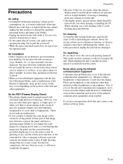
... materials. They make an ideal container in places with the unit, the following problems, such as malfunction of the Remote Commander, noisy picture, noisy sound, may block the ventilation holes. • Do not install the unit in a location near heat sources such as at...screen. Please use headphones or microphones other equipment. If you may burn into a part of video or imaging software to avoid burning this plasma display panel is eliminated, or move it away from the wall outlet if it is located on the back of white, red, blue or green remain on the screen. On cleaning To keep...
... materials. They make an ideal container in places with the unit, the following problems, such as malfunction of the Remote Commander, noisy picture, noisy sound, may block the ventilation holes. • Do not install the unit in a location near heat sources such as at...screen. Please use headphones or microphones other equipment. If you may burn into a part of video or imaging software to avoid burning this plasma display panel is eliminated, or move it away from the wall outlet if it is located on the back of white, red, blue or green remain on the screen. On cleaning To keep...
User Manual
Page 58
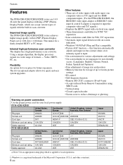
... picture settings. • ID control • Self-diagnosis function • Remote (RS-232C) connector (D-sub 9-pin) • Accepts infrared Sony Remote Commanders using SIRCS code. • Vertical setup • Closed caption decoder • Screen saver to 1024 dots × 1024 lines. Features Features The PFM-42B1/42B2/42B1E/42B2E series are 16:9 42-inch flat panel displays utilizing a PDP (Plasma Display Panel), which is applied to input the composite video and Y/C signals.) • Displays...
... picture settings. • ID control • Self-diagnosis function • Remote (RS-232C) connector (D-sub 9-pin) • Accepts infrared Sony Remote Commanders using SIRCS code. • Vertical setup • Closed caption decoder • Screen saver to 1024 dots × 1024 lines. Features Features The PFM-42B1/42B2/42B1E/42B2E series are 16:9 42-inch flat panel displays utilizing a PDP (Plasma Display Panel), which is applied to input the composite video and Y/C signals.) • Displays...

User Manual
Page 59
... IN socket Connect the supplied AC power cord to this socket and to a wall outlet. Once you connect the AC power cord, the STANDBY indicator lights up in the illustration above are all ventilation holes. Right side 6 7 (GB) Rear 2 3 4 5 The shaded areas shown in red and the display turns to the standby mode. 5 Stand installation hooks Use these hooks to install the stand (not supplied). 6 Connector panel For details on the connector panel, see "Control Button Section...
... IN socket Connect the supplied AC power cord to this socket and to a wall outlet. Once you connect the AC power cord, the STANDBY indicator lights up in the illustration above are all ventilation holes. Right side 6 7 (GB) Rear 2 3 4 5 The shaded areas shown in red and the display turns to the standby mode. 5 Stand installation hooks Use these hooks to install the stand (not supplied). 6 Connector panel For details on the connector panel, see "Control Button Section...

User Manual
Page 60
... the menu appears on . 4 Remote control detector Receives the signal from the menu displayed. 8 (GB) When the STANDBY indicator flashes, see "Self-diagnosis Function" on page 45 (GB). 3 ON indicator Lights up in red in a menu. 3 ENTER button Press to the previous menu level. Press again to go back to the standby mode. 2 STANDBY indicator Lights up in green when the display unit is turned on the display screen...
... the menu appears on . 4 Remote control detector Receives the signal from the menu displayed. 8 (GB) When the STANDBY indicator flashes, see "Self-diagnosis Function" on page 45 (GB). 3 ON indicator Lights up in red in a menu. 3 ENTER button Press to the previous menu level. Press again to go back to the standby mode. 2 STANDBY indicator Lights up in green when the display unit is turned on the display screen...
User Manual
Page 61
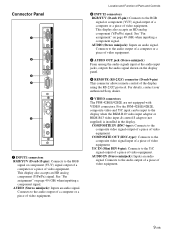
... DIN 4-pin): Connects to the display when the BKM-B10 video input adaptor or BKM-B13 video input & control S adaptor (not supplied) is installed in the display. AUDIO (Stereo minijack): Inputs an audio signal. This display also accepts an HD analog component (Y/PB/PR) signal. See "Pin assignment" on the display panel. 4 REMOTE (RS-232C) connector (D-sub 9-pin) This connector allows remote control of video equipment. For details, contact your authorized Sony dealer. 5 VIDEO connectors The PFM-42B1E/42B2E...
... DIN 4-pin): Connects to the display when the BKM-B10 video input adaptor or BKM-B13 video input & control S adaptor (not supplied) is installed in the display. AUDIO (Stereo minijack): Inputs an audio signal. This display also accepts an HD analog component (Y/PB/PR) signal. See "Pin assignment" on the display panel. 4 REMOTE (RS-232C) connector (D-sub 9-pin) This connector allows remote control of video equipment. For details, contact your authorized Sony dealer. 5 VIDEO connectors The PFM-42B1E/42B2E...

User Manual
Page 62
...connect the CONTROL S connector on the video device. IN OUT COMPOSITE INPUT 3 Y/G U/B V/R VIDEO Y/C IN 1 1 IN 2 2 CONTROL S IN CONTROL S OUT OUT 1 INPUT3 (RGB/YUV signal input) connectors RGB/YUV (RGB/YUV signal input ) connector (Phono jack): Connects to the analog RGB signal output connector (image device) or to the composite signal input connector on a video device or display to this adaptor to this connector. 2 CONTROL S IN/OUT (Control S signal input/ output) connector (Minijack) You can replace the VIDEO connectors with Control S) BKM-B12 (Not supplied) The VIDEO...
...connect the CONTROL S connector on the video device. IN OUT COMPOSITE INPUT 3 Y/G U/B V/R VIDEO Y/C IN 1 1 IN 2 2 CONTROL S IN CONTROL S OUT OUT 1 INPUT3 (RGB/YUV signal input) connectors RGB/YUV (RGB/YUV signal input ) connector (Phono jack): Connects to the analog RGB signal output connector (image device) or to the composite signal input connector on a video device or display to this adaptor to this connector. 2 CONTROL S IN/OUT (Control S signal input/ output) connector (Minijack) You can replace the VIDEO connectors with Control S) BKM-B12 (Not supplied) The VIDEO...

User Manual
Page 63
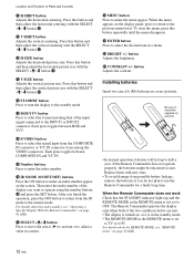
... replace the VIDEO connectors with a 10/ 100BASE-T LAN cable. 4 Keyboard connector Connect a USB keyboard. 5 Mouse connector Connect a USB mouse. 1 POWER ON switch Press to the composite output connector of an image device. COMPOSITE connector (Pinjack): Connect to turn on the display. 2 DISPLAY button Displays the input signal information and the time at the top of the display panel. Press again to another networked computer with the Network Adaptor BKM-B30NW. Location and Function of Parts and Controls Remote...
... replace the VIDEO connectors with a 10/ 100BASE-T LAN cable. 4 Keyboard connector Connect a USB keyboard. 5 Mouse connector Connect a USB mouse. 1 POWER ON switch Press to the composite output connector of an image device. COMPOSITE connector (Pinjack): Connect to turn on the display. 2 DISPLAY button Displays the input signal information and the time at the top of the display panel. Press again to another networked computer with the Network Adaptor BKM-B30NW. Location and Function of Parts and Controls Remote...
User Manual
Page 64
... about the index number, see "Operating a Specific Display With the Remote Commander" on the screen. Location and Function of the input signal connected to the normal mode. qh ID MODE (ON/SET/OFF) buttons Press the ON button to return from among the VIDEO connectors. Press this button and then adjust the vertical centering with the SELECT +M/-m button qj. Press this button repeatedly until the menu disappears. qd RGB/YUV button Press to...
... about the index number, see "Operating a Specific Display With the Remote Commander" on the screen. Location and Function of the input signal connected to the normal mode. qh ID MODE (ON/SET/OFF) buttons Press the ON button to return from among the VIDEO connectors. Press this button and then adjust the vertical centering with the SELECT +M/-m button qj. Press this button repeatedly until the menu disappears. qd RGB/YUV button Press to...
User Manual
Page 67
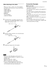
... AC plug holders (supplied) that the ferrite core does not slide. When attaching to the cables When you connect a cable to any of the terminals listed below, attach the ferrite core provided before using the RGB/YUV connectors, use the specified cable. AUDIO (INPUT1) AUDIO (INPUT2) AUDIO OUT REMOTE Y/C IN (VIDEO) AUDIO IN (VIDEO) 1 Attach the ferrite core (black) to the end of the cable closer to the PFM-42B2...
... AC plug holders (supplied) that the ferrite core does not slide. When attaching to the cables When you connect a cable to any of the terminals listed below, attach the ferrite core provided before using the RGB/YUV connectors, use the specified cable. AUDIO (INPUT1) AUDIO (INPUT2) AUDIO OUT REMOTE Y/C IN (VIDEO) AUDIO IN (VIDEO) 1 Attach the ferrite core (black) to the end of the cable closer to the PFM-42B2...
User Manual
Page 72
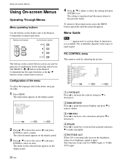
... the language used in this operating instructions. The setting is input. To return to an item when its function is not available. MA I N MENU I NPUT SELECT P I C CONTROL P I C S I ZE CONF I GH : MID 7 8 SE L ECT S E T ENTER E N D MENU 1 CONTRAST Press v to increase the contrast and press V to decrease it. 2 BRIGHTNESS Press v to make the picture brighter and press V to make it darker. 3 CHROMA Press v to increase color saturation...
... the language used in this operating instructions. The setting is input. To return to an item when its function is not available. MA I N MENU I NPUT SELECT P I C CONTROL P I C S I ZE CONF I GH : MID 7 8 SE L ECT S E T ENTER E N D MENU 1 CONTRAST Press v to increase the contrast and press V to decrease it. 2 BRIGHTNESS Press v to make the picture brighter and press V to make it darker. 3 CHROMA Press v to increase color saturation...
User Manual
Page 73
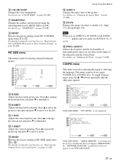
... of horizontal pixels when you cannot set ASPECT to the left. q; qs V SHIFT Adjusts the vertical centering. Using On-screen Menus qf ASPECT Changes the aspect ratio of two pages; PIC SIZE menu This menu is used for resizing and positioning the picture. 9 P I C S I ON : OF F w; H SHIFT Adjusts the horizontal centering. COLOR SYS T EM : AUTO wa YUV LEVEL SCREEN F I A L R EMO T E N E TWO R K A D A P T O R wk SE L ECT S E T ENTER E N D MENU PFM-42B1/42B1E: "SERIAL REMOTE" is not displayed. wg...
... of horizontal pixels when you cannot set ASPECT to the left. q; qs V SHIFT Adjusts the vertical centering. Using On-screen Menus qf ASPECT Changes the aspect ratio of two pages; PIC SIZE menu This menu is used for resizing and positioning the picture. 9 P I C S I ON : OF F w; H SHIFT Adjusts the horizontal centering. COLOR SYS T EM : AUTO wa YUV LEVEL SCREEN F I A L R EMO T E N E TWO R K A D A P T O R wk SE L ECT S E T ENTER E N D MENU PFM-42B1/42B1E: "SERIAL REMOTE" is not displayed. wg...

User Manual
Page 74
... "Controlling Power On/Off Automatically (Power Control Function)" on page 36 (GB). wj SERIAL REMOTE (PFM-42B2/42B2E only) Setting the Serial Remote. wl LOAD Recalls the preset settings. SAVE Saves the settings. SMPTE: SMPTE level signal BETA: BETACAM level signal ws SCREEN FILL Selects the point of time until the system goes into the power saving mode. For details, see "Displaying closed captions. e; Using On-screen Menus qj DISPLAY Select ON to display the input signal information...
... "Controlling Power On/Off Automatically (Power Control Function)" on page 36 (GB). wj SERIAL REMOTE (PFM-42B2/42B2E only) Setting the Serial Remote. wl LOAD Recalls the preset settings. SAVE Saves the settings. SMPTE: SMPTE level signal BETA: BETACAM level signal ws SCREEN FILL Selects the point of time until the system goes into the power saving mode. For details, see "Displaying closed captions. e; Using On-screen Menus qj DISPLAY Select ON to display the input signal information...
User Manual
Page 75
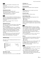
... disable the control buttons on the 1 (standby) switch / indicator section also flashes. This item indicates whether the cooling fans work properly. If the ambient temperature is indicated, see "Using Other Remote Commander Models" on page 47 (GB). The setting in a poorly ventilated location. es REMOTE MODE Selects the Remote Commander mode. You cannot change the Remote Commander mode, use the buttons on the display unit. To cancel the REMOTE ONLY mode, set the number, use...
... disable the control buttons on the 1 (standby) switch / indicator section also flashes. This item indicates whether the cooling fans work properly. If the ambient temperature is indicated, see "Using Other Remote Commander Models" on page 47 (GB). The setting in a poorly ventilated location. es REMOTE MODE Selects the Remote Commander mode. You cannot change the Remote Commander mode, use the buttons on the display unit. To cancel the REMOTE ONLY mode, set the number, use...
User Manual
Page 76
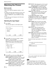
... (GB). The currently selected input signal and INPUT SELECT menu appear on the display panel. Watching the Picture Watching the Picture Before you start • Turn on the display. • Turn on the connected equipment and play a video source. • To display the input signal information on the screen when turning on the power or switching the input signal, set "DISPLAY" in the CONFIG (1/2) menu to ON. • To select the on-screen language used in the VIDEO connector unit. (Only when...
... (GB). The currently selected input signal and INPUT SELECT menu appear on the display panel. Watching the Picture Watching the Picture Before you start • Turn on the display. • Turn on the connected equipment and play a video source. • To display the input signal information on the screen when turning on the power or switching the input signal, set "DISPLAY" in the CONFIG (1/2) menu to ON. • To select the on-screen language used in the VIDEO connector unit. (Only when...
User Manual
Page 79
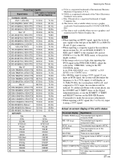
... SIZE menu, or the picture might oscillate. • If the image color is too light after inputting the DVD signal in the PFM-42B1/42B1E, adjust the color in the "CHROMA" setting in the CONFIG menu. • For 480/60p, input it using a YUV signal. NTSC (e.g.) The selected input signal is selected for VIDEO. 27 (GB) VIDEO Y/C Y/C video input is no input signal. NO SYNC There is selected for VIDEO. Preset input signals Signal name Color system or horizontal/ vertical frequency Computer signals 1 VGAa)-1 (VGA...
... SIZE menu, or the picture might oscillate. • If the image color is too light after inputting the DVD signal in the PFM-42B1/42B1E, adjust the color in the "CHROMA" setting in the CONFIG menu. • For 480/60p, input it using a YUV signal. NTSC (e.g.) The selected input signal is selected for VIDEO. 27 (GB) VIDEO Y/C Y/C video input is no input signal. NO SYNC There is selected for VIDEO. Preset input signals Signal name Color system or horizontal/ vertical frequency Computer signals 1 VGAa)-1 (VGA...
User Manual
Page 96
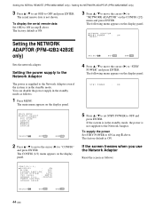
... and press ENTER. The factory default is ON. Setting the power supply to the Network Adaptor The power is in the standby mode. You can disable the power supply in the standby mode, the power is not shown. The main menu appears on the display panel. 5 Press v / V to set OSD to "STBY POWER" and press ENTER. S T B Y P OWER : ON MA I N MENU I NPUT SELECT P I C CONTROL P I C S I ZE CONF I L L : CENTER P OWE R C O N T R O L SCREEN SAVER SE L ECT...
... and press ENTER. The factory default is ON. Setting the power supply to the Network Adaptor The power is in the standby mode. You can disable the power supply in the standby mode, the power is not shown. The main menu appears on the display panel. 5 Press v / V to set OSD to "STBY POWER" and press ENTER. S T B Y P OWER : ON MA I N MENU I NPUT SELECT P I C CONTROL P I C S I ZE CONF I L L : CENTER P OWE R C O N T R O L SCREEN SAVER SE L ECT...

User Manual
Page 99
Using Other Remote Commander Models Remote Commander model RM-854 REMOTE MODE setting TV Input selection INPUT1 RGB INPUT2 - On-screen information DISPLAY RM-921 TV RGB1 RGB2 LINE MENU ENTER SELECT+M SELECT-m - - - VIDEO LINE1 Menu operation MENU MENU ENTER ENTER v + V - Picture adjustment Contrast CONTRAST+/- Phase PHASE+/- HUE+/- Using Other Remote Commander Models The following operations can be carried out using other Remote Commander models. • Power on/off • Input selection • Menu operations • Picture adjustments: contrast, phase and chroma...
Using Other Remote Commander Models Remote Commander model RM-854 REMOTE MODE setting TV Input selection INPUT1 RGB INPUT2 - On-screen information DISPLAY RM-921 TV RGB1 RGB2 LINE MENU ENTER SELECT+M SELECT-m - - - VIDEO LINE1 Menu operation MENU MENU ENTER ENTER v + V - Picture adjustment Contrast CONTRAST+/- Phase PHASE+/- HUE+/- Using Other Remote Commander Models The following operations can be carried out using other Remote Commander models. • Power on/off • Input selection • Menu operations • Picture adjustments: contrast, phase and chroma...
User Manual
Page 100
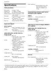
... Display Panel Display resolution 1 024 dots (horizontal) × 1 024 lines (vertical) Pixel pitch 0.90 (horizontal) × 0.51 (vertical) mm (1⁄16 × 1⁄32 inches) Picture size 921 (horizontal) × 522 (vertical) mm (36 3⁄8 × 20 5⁄8 inches) Panel size 42-inch (diagonal 1 058 mm) Safety regulations UL1950, CSA No. 950 (c-UL), FCC Class B, IC Class B, EN60 950 (NEMKO), CE, C-Tick Component Input Adaptor (with Control S) BKM-B12 (Not supplied...
... Display Panel Display resolution 1 024 dots (horizontal) × 1 024 lines (vertical) Pixel pitch 0.90 (horizontal) × 0.51 (vertical) mm (1⁄16 × 1⁄32 inches) Picture size 921 (horizontal) × 522 (vertical) mm (36 3⁄8 × 20 5⁄8 inches) Panel size 42-inch (diagonal 1 058 mm) Safety regulations UL1950, CSA No. 950 (c-UL), FCC Class B, IC Class B, EN60 950 (NEMKO), CE, C-Tick Component Input Adaptor (with Control S) BKM-B12 (Not supplied...


