
User Guide
Page 16
VAIO Slimtop™ LCD Computer User Guide Back Panel Overview The back panel of your computer. The icons on the back panel help locate and identify the connectors on your computer contains the connectors for supplied and optional accessories. Locating Controls and Connectors Back Panel (PCV-LX700/PCV-LX800) MONITOR LINE NETWORK/USB i.LINK S400 PHONES LINE IN MIC PHONE LCD USB 1 AC Input connector Connects the supplied power cord. 2 T-Lever A handle that is used to remove the unit cover. 3 Monitor connector Connects a standard CRT display. 16
VAIO Slimtop™ LCD Computer User Guide Back Panel Overview The back panel of your computer. The icons on the back panel help locate and identify the connectors on your computer contains the connectors for supplied and optional accessories. Locating Controls and Connectors Back Panel (PCV-LX700/PCV-LX800) MONITOR LINE NETWORK/USB i.LINK S400 PHONES LINE IN MIC PHONE LCD USB 1 AC Input connector Connects the supplied power cord. 2 T-Lever A handle that is used to remove the unit cover. 3 Monitor connector Connects a standard CRT display. 16
User Guide
Page 17
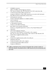
...Connects a USB device. ✍ i.LINK is a trademark of Sony used only to the computer. All products with an i.LINK connector may not communicate with each other than the LCD monitor that is supplied with (Network) is located on the back panel.... or computer speakers. 7 Line In connector Connects an audio device. 8 Microphone Connector Connects a microphone(optional). 9 i.LINK® 6-pin connector (IEEE1394) Connects a compatible digital device such as a Sony Digital Handycam® Camcorder. 10 LCD monitor (display) connector Connects the VAIO Slimtop™ LCD monitor to ...
...Connects a USB device. ✍ i.LINK is a trademark of Sony used only to the computer. All products with an i.LINK connector may not communicate with each other than the LCD monitor that is supplied with (Network) is located on the back panel.... or computer speakers. 7 Line In connector Connects an audio device. 8 Microphone Connector Connects a microphone(optional). 9 i.LINK® 6-pin connector (IEEE1394) Connects a compatible digital device such as a Sony Digital Handycam® Camcorder. 10 LCD monitor (display) connector Connects the VAIO Slimtop™ LCD monitor to ...

User Guide
Page 18
... display. 18 See "AutoAlert E-mail Notification System" . 3 Brightness control Adjusts the brightness of the screen. 4 Volume control Adjusts the volume of e-mail. The PCV-LX800 is supplied with a QVGA (1280 x 960), and the PCV-LX700 is supplied with an LCD monitor. VAIO Slimtop™ LCD Computer User Guide LCD Overview Your VAIO Slimtop Computer is supplied with a XGA (1024 x 768).
... display. 18 See "AutoAlert E-mail Notification System" . 3 Brightness control Adjusts the brightness of the screen. 4 Volume control Adjusts the volume of e-mail. The PCV-LX800 is supplied with a QVGA (1280 x 960), and the PCV-LX700 is supplied with an LCD monitor. VAIO Slimtop™ LCD Computer User Guide LCD Overview Your VAIO Slimtop Computer is supplied with a XGA (1024 x 768).
User Guide
Page 25
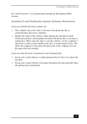
... System Software Restrictions If you use software that uses a phone line ❑ The computer may not be able to disconnect the phone line due to communication and server conditions. ❑ Monitor the status of time. This allows the computer to disconnect the phone line automatically when all mail has been downloaded. 25 If...
... System Software Restrictions If you use software that uses a phone line ❑ The computer may not be able to disconnect the phone line due to communication and server conditions. ❑ Monitor the status of time. This allows the computer to disconnect the phone line automatically when all mail has been downloaded. 25 If...
User Guide
Page 36
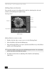
Your clip displays with the new effect on the Effect tray monitor. 4 See help for instructions on the clip in the Working panel monitor. Working Panel Monitor Sound Color Speed Trim Palette Effect Palette Effect Knobs Adding effects to a scene or a clip 1 Double-click the clip or ...Effects palette on the Working Panel. ✍ To preview an Effect, click on adjusting effect duration and replaying clips/scenes. 36 VAIO Slimtop™ LCD Computer User Guide Editing Clips and Scenes You can edit your movie by adding effects and text, adjusting the color and contrast, and modifying...
Your clip displays with the new effect on the Effect tray monitor. 4 See help for instructions on the clip in the Working panel monitor. Working Panel Monitor Sound Color Speed Trim Palette Effect Palette Effect Knobs Adding effects to a scene or a clip 1 Double-click the clip or ...Effects palette on the Working Panel. ✍ To preview an Effect, click on adjusting effect duration and replaying clips/scenes. 36 VAIO Slimtop™ LCD Computer User Guide Editing Clips and Scenes You can edit your movie by adding effects and text, adjusting the color and contrast, and modifying...
User Guide
Page 74
VAIO Slimtop™ LCD Computer User Guide E electronic documentation 65 equipment 60 European power settings 59 G glare 12 H handling diskettes 63 hard disk 63 hardware adding additional precaution 60 troubleshooting ... disposal 7 safety precautions 7 locations, choosing 11 losing power 59 M Memory Stick media slot 15 using 26 microphones troubleshooting 54 minimizing glare 12 modem troubleshooting 53 monitor connector 17 mouse 11 cleaning 55 troubleshooting 55 O online help 65 support options 65 opening applications problems with 51 CD-RW tray problems with 51...
VAIO Slimtop™ LCD Computer User Guide E electronic documentation 65 equipment 60 European power settings 59 G glare 12 H handling diskettes 63 hard disk 63 hardware adding additional precaution 60 troubleshooting ... disposal 7 safety precautions 7 locations, choosing 11 losing power 59 M Memory Stick media slot 15 using 26 microphones troubleshooting 54 minimizing glare 12 modem troubleshooting 53 monitor connector 17 mouse 11 cleaning 55 troubleshooting 55 O online help 65 support options 65 opening applications problems with 51 CD-RW tray problems with 51...
Reference Manual
Page 12
xii VAIO Slimtop™ Reference Manual Chapter 3 - System Board Connectors 44 Front Panel Header 44 IDE Connectors 45 PCI Slot Connectors 46 Memory Module (DIMM) Connectors 47 Power (ATX PWR) Connector 48 Fan (CPU FAN, CTRL PWR) Connectors 49 USB Connectors 50 VGA MONITOR Connector 51 LCD ...Connector 52 Wake On LAN (WOL_CON) Connector 53 PHONES, LINE IN, and MIC Connectors 54 Sony Memory Stick Slot Connector 55 i.LINK Interface Header Connectors 55 i.LINK Connectors 57...
xii VAIO Slimtop™ Reference Manual Chapter 3 - System Board Connectors 44 Front Panel Header 44 IDE Connectors 45 PCI Slot Connectors 46 Memory Module (DIMM) Connectors 47 Power (ATX PWR) Connector 48 Fan (CPU FAN, CTRL PWR) Connectors 49 USB Connectors 50 VGA MONITOR Connector 51 LCD ...Connector 52 Wake On LAN (WOL_CON) Connector 53 PHONES, LINE IN, and MIC Connectors 54 Sony Memory Stick Slot Connector 55 i.LINK Interface Header Connectors 55 i.LINK Connectors 57...
Reference Manual
Page 22
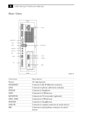
Connects to output connector on audio device. Connects to USB devices. Connects to USB devices. Connects to telephone. Connects to phone cable from wall jack. Connects to RJ-45 Ethernet connector. Connects to VGA monitor (optional). Connects to headphones. Connects to microphone connector on audio device. 8 VAIO Slimtop™ Reference Manual Rear View MONITOR USB1 USB2 PHONES LINE IN MIC i.LINK LCD Connector Power ETHERNET LINE PHONE USB3 MONITOR USB1, USB2 PHONES LINE IN MIC Power ETHERNET LINE PHONE USB3 SHA0007.VSD Description AC input power.
Connects to output connector on audio device. Connects to USB devices. Connects to USB devices. Connects to telephone. Connects to phone cable from wall jack. Connects to RJ-45 Ethernet connector. Connects to VGA monitor (optional). Connects to headphones. Connects to microphone connector on audio device. 8 VAIO Slimtop™ Reference Manual Rear View MONITOR USB1 USB2 PHONES LINE IN MIC i.LINK LCD Connector Power ETHERNET LINE PHONE USB3 MONITOR USB1, USB2 PHONES LINE IN MIC Power ETHERNET LINE PHONE USB3 SHA0007.VSD Description AC input power.

Reference Manual
Page 23
A 6-pin i.LINK connector can supply power from the computer to the device. A 4-pin i.LINK connector cannot supply power to the device if the device also has a 6-pin i.LINK connector. Identifying Components 9 Connector i.LINK (IEEE1394)* LCD Description Connects to a 6-pin i.LINK device, use the i.LINK connector on the back of the system. Connects to VAIO Slimtop™ LCD monitor. * To connect to digital device that has a 4-pin or 6-pin i.LINK connector.
A 6-pin i.LINK connector can supply power from the computer to the device. A 4-pin i.LINK connector cannot supply power to the device if the device also has a 6-pin i.LINK connector. Identifying Components 9 Connector i.LINK (IEEE1394)* LCD Description Connects to a 6-pin i.LINK device, use the i.LINK connector on the back of the system. Connects to VAIO Slimtop™ LCD monitor. * To connect to digital device that has a 4-pin or 6-pin i.LINK connector.

Reference Manual
Page 24
..., and USB3) are available. Rear panel USB3 on the front panel between the i.LINK connector and the Sony Memory Stick slot. 10 VAIO Slimtop™ Reference Manual I/O Connectors The following section identifies the various I/O connectors. MONITOR The MONITOR connector is a standard 15-pin female high-density VGAtype connector and is located on Modem card at...
..., and USB3) are available. Rear panel USB3 on the front panel between the i.LINK connector and the Sony Memory Stick slot. 10 VAIO Slimtop™ Reference Manual I/O Connectors The following section identifies the various I/O connectors. MONITOR The MONITOR connector is a standard 15-pin female high-density VGAtype connector and is located on Modem card at...

Reference Manual
Page 26
... the computer to a telephone line that comes from the wall jack, and the PHONE jack is located on the Modem plug-in card. These connectors are accessible from the wall into the modem's PHONE jack, and a telephone into the LINE jack, will not work correctly. 12 VAIO Slimtop™... panel. LINE and PHONE The LINE and PHONE jacks are standard RJ-11 female phone jacks. Do not connect any LCD monitor other than the Sony VAIO Slimtop LCD monitor. They are physically identical and have identical connections. These jacks are located on the Modem plug-in card and are located...
... the computer to a telephone line that comes from the wall jack, and the PHONE jack is located on the Modem plug-in card. These connectors are accessible from the wall into the modem's PHONE jack, and a telephone into the LINE jack, will not work correctly. 12 VAIO Slimtop™... panel. LINE and PHONE The LINE and PHONE jacks are standard RJ-11 female phone jacks. Do not connect any LCD monitor other than the Sony VAIO Slimtop LCD monitor. They are physically identical and have identical connections. These jacks are located on the Modem plug-in card and are located...
Reference Manual
Page 29
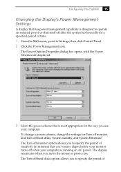
... tab displayed. 3 Select the power scheme that is most appropriate for a specified period of The display reactivates when you use your computer is running on reduced power or shut itself off hard disks, System standby, and System Hibernate. The Turn off hard disks option allows... you want to elapse before your monitor turns off when your computer. Configuring Your System 15 Changing the Display's Power Management Settings A display that has power management capability is designed to operate...
... tab displayed. 3 Select the power scheme that is most appropriate for a specified period of The display reactivates when you use your computer is running on reduced power or shut itself off hard disks, System standby, and System Hibernate. The Turn off hard disks option allows... you want to elapse before your monitor turns off when your computer. Configuring Your System 15 Changing the Display's Power Management Settings A display that has power management capability is designed to operate...
Reference Manual
Page 57
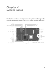
Chapter 4 System Board This chapter identifies each component on the system board and provides a detailed description of each connector and jumper on the system board. switch) O1 2 N CPU Fan Secondary IDE Primary IDE CPU Sony Panel to Modem/ USB3 PCMCIA Socket Sony Memory Stick USB4 i.LINK 1394 i.LINK OM04581.VSD 43 Battery ATX PWR Wake On LAN (not used) PWR Fan VGA Monitor USB1, USB2, Ethernet Line In Line Out Mic i.LINK 1394 i.LINK LCD Monitor (unused) CD-IN Memory SW1 (Config.
Chapter 4 System Board This chapter identifies each component on the system board and provides a detailed description of each connector and jumper on the system board. switch) O1 2 N CPU Fan Secondary IDE Primary IDE CPU Sony Panel to Modem/ USB3 PCMCIA Socket Sony Memory Stick USB4 i.LINK 1394 i.LINK OM04581.VSD 43 Battery ATX PWR Wake On LAN (not used) PWR Fan VGA Monitor USB1, USB2, Ethernet Line In Line Out Mic i.LINK 1394 i.LINK LCD Monitor (unused) CD-IN Memory SW1 (Config.

Reference Manual
Page 65
VGA MONITOR 5 1 O1 2 N 15 11 VGA MONITOR connector Pin Signal Name 1 RED 2 GREEN 3 BLUE 4 GND 5 DDC GND 6 RED GND 7 GREEN GND 8 BLUE GND 9 NC 10 GND 11 GND 12 SDA 13 HORIZONTAL SYNC 14 VERTICAL SYNC 15 SCL OM04701D.VSD System Board 51 VGA MONITOR Connector The VGA MONITOR connector is a 15-pin D-sub female connector.
VGA MONITOR 5 1 O1 2 N 15 11 VGA MONITOR connector Pin Signal Name 1 RED 2 GREEN 3 BLUE 4 GND 5 DDC GND 6 RED GND 7 GREEN GND 8 BLUE GND 9 NC 10 GND 11 GND 12 SDA 13 HORIZONTAL SYNC 14 VERTICAL SYNC 15 SCL OM04701D.VSD System Board 51 VGA MONITOR Connector The VGA MONITOR connector is a 15-pin D-sub female connector.

Reference Manual
Page 66
The Sony VAIO Slimtop LCD monitor that came with earlier PCV-L models is a 32-pin MDR-type connector for the Sony VAIO Slimtop LCD monitor. Do not connect any LCD other than the Sony VAIO Slimtop LCD monitor that came with the PCV-LX700/PCV-LX800. O1 2 N LCD KY0094.VSD ! 52 VAIO Slimtop™ Reference Manual LCD Connector The LCD connector is not compatible with the PCV-LX700/ PCV-LX800 system.
The Sony VAIO Slimtop LCD monitor that came with earlier PCV-L models is a 32-pin MDR-type connector for the Sony VAIO Slimtop LCD monitor. Do not connect any LCD other than the Sony VAIO Slimtop LCD monitor that came with the PCV-LX700/PCV-LX800. O1 2 N LCD KY0094.VSD ! 52 VAIO Slimtop™ Reference Manual LCD Connector The LCD connector is not compatible with the PCV-LX700/ PCV-LX800 system.
Reference Manual
Page 80
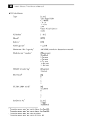
66 VAIO Slimtop™ Reference Manual IDE Sub-Menus Type Cylinders* Heads† Sectors† CHS Capacity* Maximum LBA Capacity* Multi-Sector Transfers* SMART Monitoring* PIO Mode‡ ULTRA DMA Mode† Set Device As** [Auto] User Type HDD CD-ROM LS-120 ZIP-100 MO Other ATAPI Device None [ ...
66 VAIO Slimtop™ Reference Manual IDE Sub-Menus Type Cylinders* Heads† Sectors† CHS Capacity* Maximum LBA Capacity* Multi-Sector Transfers* SMART Monitoring* PIO Mode‡ ULTRA DMA Mode† Set Device As** [Auto] User Type HDD CD-ROM LS-120 ZIP-100 MO Other ATAPI Device None [ ...
Reference Manual
Page 107
... chipset specifications 87 CMOS configuring 14 See Also BIOS setup utility 14 specifications 91 CMOS switch 59 codes, beeps 79 communications specifications 89 computer lithium ion battery vii computer safety information ii configuration switch 59 configuring CMOS setup utility 14 power management 15 system board 18 connectors fan 49 i.LINK (IEEE-1394... IDE 45 LCD 52 LINE 61 LINE IN 54 LINE OUT 54 MIC 54 modem card 61 PHONES 54 power 48 PRINTER 51 SERIAL 51 Sony Memory Stick slot 55 system board 44 TELEPHONE 61 USB 6, 50 VGA MONITOR 10, 51 Wake On LAN 53 93
... chipset specifications 87 CMOS configuring 14 See Also BIOS setup utility 14 specifications 91 CMOS switch 59 codes, beeps 79 communications specifications 89 computer lithium ion battery vii computer safety information ii configuration switch 59 configuring CMOS setup utility 14 power management 15 system board 18 connectors fan 49 i.LINK (IEEE-1394... IDE 45 LCD 52 LINE 61 LINE IN 54 LINE OUT 54 MIC 54 modem card 61 PHONES 54 power 48 PRINTER 51 SERIAL 51 Sony Memory Stick slot 55 system board 44 TELEPHONE 61 USB 6, 50 VGA MONITOR 10, 51 Wake On LAN 53 93

Reference Manual
Page 108
... map 83 I/O connectors Ethernet 11 i.LINK (IEEE1394) 11 LCD 12 LINE and PHONE 12 LINE IN 11 MIC 11 PHONE 11 USB 10, 50 VGA MONITOR 10 I/O slot covering 41 I /O slot 41 CPU See processor D DIMM 47 configurations 88 See Also memory modules display, power management 15 disposal of lithium ion... 37 header - See fax/modem fax/modem add-in card 24 system memory 33 interference v IRQ assignments 82 L L2 cache specifications 88 LCD - See Also monitor LCD connector 12, 52 LINE and PHONE connectors 12 LINE IN connector 11, 54 LINE OUT connector 54 lithium battery, replacing 28 lithium ion battery...
... map 83 I/O connectors Ethernet 11 i.LINK (IEEE1394) 11 LCD 12 LINE and PHONE 12 LINE IN 11 MIC 11 PHONE 11 USB 10, 50 VGA MONITOR 10 I/O slot covering 41 I /O slot 41 CPU See processor D DIMM 47 configurations 88 See Also memory modules display, power management 15 disposal of lithium ion... 37 header - See fax/modem fax/modem add-in card 24 system memory 33 interference v IRQ assignments 82 L L2 cache specifications 88 LCD - See Also monitor LCD connector 12, 52 LINE and PHONE connectors 12 LINE IN connector 11, 54 LINE OUT connector 54 lithium battery, replacing 28 lithium ion battery...
Reference Manual
Page 110
96 VAIO Computer Reference Manual memory module connector 47 power connector 48 PRINTER connector 51 SERIAL connector 51 slot connectors 46 USB connectors 50 VGA MONITOR connector 51 system cover removing 22 replacing 23 system I/O address map 83 system memory, installing 33 T Telephone Consumer Protection Act of 1991 vi TV interference v U USB connectors 6, 10, 50 user password 78 V VGA MONITOR I/O connector 10 See Also LCD Monitor and display VGA MONITOR connector 51 W Wake On LAN connector 53
96 VAIO Computer Reference Manual memory module connector 47 power connector 48 PRINTER connector 51 SERIAL connector 51 slot connectors 46 USB connectors 50 VGA MONITOR connector 51 system cover removing 22 replacing 23 system I/O address map 83 system memory, installing 33 T Telephone Consumer Protection Act of 1991 vi TV interference v U USB connectors 6, 10, 50 user password 78 V VGA MONITOR I/O connector 10 See Also LCD Monitor and display VGA MONITOR connector 51 W Wake On LAN connector 53


