System Reference Manual (primary manual)
Page 12
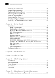
System Board Connectors 48 Front Panel Header 48 Diskette Drive Connector 49 Memory Module (DIMM) Connectors 50 PCI Slot Connectors 51 IDE Connectors 52 Power Connector 52 KEYBOARD and MOUSE Connectors 53 USB Connectors 54 PRINTER, i.LINK... 62 Chapter 5 - Miscellaneous Technical Information About User and Supervisor Passwords 76 xii VAIO® Reference Manual Installing an Add-In Card 26 Removing an Add-in Card 28 Replacing the Lithium Battery 30 Removing a Memory Module 33 Installing System Memory 36 Removing a Slot Cover 40 Covering an Open I/O Slot 41 Installing a ...
System Board Connectors 48 Front Panel Header 48 Diskette Drive Connector 49 Memory Module (DIMM) Connectors 50 PCI Slot Connectors 51 IDE Connectors 52 Power Connector 52 KEYBOARD and MOUSE Connectors 53 USB Connectors 54 PRINTER, i.LINK... 62 Chapter 5 - Miscellaneous Technical Information About User and Supervisor Passwords 76 xii VAIO® Reference Manual Installing an Add-In Card 26 Removing an Add-in Card 28 Replacing the Lithium Battery 30 Removing a Memory Module 33 Installing System Memory 36 Removing a Slot Cover 40 Covering an Open I/O Slot 41 Installing a ...
System Reference Manual (primary manual)
Page 36
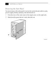
22 VAIO® Reference Manual Removing the Side Panel You must remove the side panel to access the system board, add-in cards, power supply, battery, memory, and internal drives. 1 From the rear of the unit, remove the single screw on the right side. 2 Slide back the panel about ½ inch, then lift out. KY0064B.VSD
22 VAIO® Reference Manual Removing the Side Panel You must remove the side panel to access the system board, add-in cards, power supply, battery, memory, and internal drives. 1 From the rear of the unit, remove the single screw on the right side. 2 Slide back the panel about ½ inch, then lift out. KY0064B.VSD

System Reference Manual (primary manual)
Page 43
...to discard changes, then press Enter to exit the BIOS Setup Utility. 6 Turn off . Otherwise it is not necessary to power the CMOS memory. ! Do not handle damaged or leaking batteries. When the values are different from their default values. Removing, Installing, and Replacing Components 29 ...to this time, and you restore the BIOS settings later. 4 Select Exit Discarding Changes from the Start menu, and then selecting Restart the computer. 2 If the error message "Error: Check date and time settings"appears during the reboot sequence, press F2 during the reboot process to...
...to discard changes, then press Enter to exit the BIOS Setup Utility. 6 Turn off . Otherwise it is not necessary to power the CMOS memory. ! Do not handle damaged or leaking batteries. When the values are different from their default values. Removing, Installing, and Replacing Components 29 ...to this time, and you restore the BIOS settings later. 4 Select Exit Discarding Changes from the Start menu, and then selecting Restart the computer. 2 If the error message "Error: Check date and time settings"appears during the reboot sequence, press F2 during the reboot process to...
System Reference Manual (primary manual)
Page 46
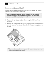
...supply to the chassis is the same screw that secures the side panel to remove a memory module if you change the memory configuration or replace a bad module. ! 32 VAIO® Reference Manual Removing a Memory Module You may need to the chassis. Before opening the system unit, save any open... files, exit the Windows® operating system, turn off the power of the computer and all attached ...
...supply to the chassis is the same screw that secures the side panel to remove a memory module if you change the memory configuration or replace a bad module. ! 32 VAIO® Reference Manual Removing a Memory Module You may need to the chassis. Before opening the system unit, save any open... files, exit the Windows® operating system, turn off the power of the computer and all attached ...

System Reference Manual (primary manual)
Page 47
KY0073.VSD 4 Push down the handle on each side of the memory module to access the module connector. Push out Handles KY0042.VS ✍ Gently push the power supply cables and ribbon cables aside as you wish to remove. Removing, Installing, and Replacing Components 33 3 Locate the memory module you reach inside the system to eject the module from its socket.
KY0073.VSD 4 Push down the handle on each side of the memory module to access the module connector. Push out Handles KY0042.VS ✍ Gently push the power supply cables and ribbon cables aside as you wish to remove. Removing, Installing, and Replacing Components 33 3 Locate the memory module you reach inside the system to eject the module from its socket.
System Reference Manual (primary manual)
Page 48
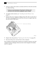
...VAIO® Reference Manual 5 Grasp one edge of the chassis opening until the metal tab on the power supply slips into slot in your body before handling the memory module. 6 To install system memory, see "Replacing the Side Panel" on page 25). 9 Reconnect the power cord and turn on the computer. Your computer... automatically recognizes any exposed metal part of the chassis to discharge static electricity in CD-RW drive AUR002.VSD 8 Replace the side panel (see "Installing System Memory" on page 36. 7 Replace the power ...
...VAIO® Reference Manual 5 Grasp one edge of the chassis opening until the metal tab on the power supply slips into slot in your body before handling the memory module. 6 To install system memory, see "Replacing the Side Panel" on page 25). 9 Reconnect the power cord and turn on the computer. Your computer... automatically recognizes any exposed metal part of the chassis to discharge static electricity in CD-RW drive AUR002.VSD 8 Replace the side panel (see "Installing System Memory" on page 36. 7 Replace the power ...
System Reference Manual (primary manual)
Page 49
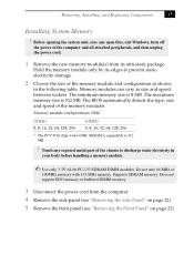
...computer. 4 Remove the side panel (see "Removing the Side Panel" on page 22). 5 Remove the front panel (see "Removing the Front Panel" on page 23). The maximum memory size is 512 MB. Memory module configurations (MB)* DIMM1 0, 8, 16, 32, 64, 128, 256 DIMM2 0, 8, 16, 32, 64, 128, 256 * The PCV-J150 ships with 133 MHz memory.... Supports SDRAM memory. Removing, Installing, and Replacing Components 35 Installing System Memory ! Memory modules can vary in the following table. Do not mix 66 MHz or 100MHz memory with 64 MB. The BIOS...
...computer. 4 Remove the side panel (see "Removing the Side Panel" on page 22). 5 Remove the front panel (see "Removing the Front Panel" on page 23). The maximum memory size is 512 MB. Memory module configurations (MB)* DIMM1 0, 8, 16, 32, 64, 128, 256 DIMM2 0, 8, 16, 32, 64, 128, 256 * The PCV-J150 ships with 133 MHz memory.... Supports SDRAM memory. Removing, Installing, and Replacing Components 35 Installing System Memory ! Memory modules can vary in the following table. Do not mix 66 MHz or 100MHz memory with 64 MB. The BIOS...
System Reference Manual (primary manual)
Page 50
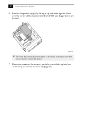
36 VAIO® Reference Manual 6 Remove the power supply by lifting it up and rest it upside down over the corner of the chassis where the CD-RW and floppy drives are located. AUR001.VSD ✍ The screw that secures the power supply to the chassis is the same screw that secures the side panel to the chassis. 7 If necessary, remove the memory module you wish to replace (see "Removing a Memory Module" on page 33).
36 VAIO® Reference Manual 6 Remove the power supply by lifting it up and rest it upside down over the corner of the chassis where the CD-RW and floppy drives are located. AUR001.VSD ✍ The screw that secures the power supply to the chassis is the same screw that secures the side panel to the chassis. 7 If necessary, remove the memory module you wish to replace (see "Removing a Memory Module" on page 33).

System Reference Manual (primary manual)
Page 51
Press down here Handles Memory module (DIMM) 1 9 Carefully but firmly insert the edge of the module into the socket. ✍ Gently push the power supply cables and ribbon cables aside ... system to press down on the socket. If the handles are straight up and locked into place. Removing, Installing, and Replacing Components 37 8 Align the memory module over the appropriate socket, noting the location of the module until the module is fully seated. ✍ When the module is fully seated, the...
Press down here Handles Memory module (DIMM) 1 9 Carefully but firmly insert the edge of the module into the socket. ✍ Gently push the power supply cables and ribbon cables aside ... system to press down on the socket. If the handles are straight up and locked into place. Removing, Installing, and Replacing Components 37 8 Align the memory module over the appropriate socket, noting the location of the module until the module is fully seated. ✍ When the module is fully seated, the...

System Reference Manual (primary manual)
Page 52
Tab fits into the slot in CD-RW drive AUR002.VSD 12 Replace the side panel (see "Replacing the Side Panel" on page 25). 13 Reconnect the power cord and turn on the computer. No further action is required. Your computer automatically recognizes the extra memory and will configure itself accordingly when you turn on the computer. 38 VAIO® Reference Manual 11 Replace the power supply by sliding it down the rails on each side of the chassis opening until the metal tab on the power supply slips into slot in the CD-RW drive.
Tab fits into the slot in CD-RW drive AUR002.VSD 12 Replace the side panel (see "Replacing the Side Panel" on page 25). 13 Reconnect the power cord and turn on the computer. No further action is required. Your computer automatically recognizes the extra memory and will configure itself accordingly when you turn on the computer. 38 VAIO® Reference Manual 11 Replace the power supply by sliding it down the rails on each side of the chassis opening until the metal tab on the power supply slips into slot in the CD-RW drive.

System Reference Manual (primary manual)
Page 59
Keyboard, Mouse CPU CPU Fan Memory USB1/2/3 Power Supply Fan Parallel (top), i.Link, Monitor IEEE 1394 Header (not used) Serial (top) MicIn, Line In, Line Out Video (not used) CD-In (to CD-RW drive) Aux-In (not used) Wake-On-LAN (not used) PCI slot 4 PCI slot 3 PCI slot 2 PCI slot 1 CMOS Clear Normal 1-2 Clear 2-3 Power Supply Diskette Secondary IDE Primary IDE VIRQ Battery Front panel header OM04581.VS 47 Chapter 4 System Board This chapter identifies each component on the system board and provides a detailed description of each connector, jumper, and switch on the system board.
Keyboard, Mouse CPU CPU Fan Memory USB1/2/3 Power Supply Fan Parallel (top), i.Link, Monitor IEEE 1394 Header (not used) Serial (top) MicIn, Line In, Line Out Video (not used) CD-In (to CD-RW drive) Aux-In (not used) Wake-On-LAN (not used) PCI slot 4 PCI slot 3 PCI slot 2 PCI slot 1 CMOS Clear Normal 1-2 Clear 2-3 Power Supply Diskette Secondary IDE Primary IDE VIRQ Battery Front panel header OM04581.VS 47 Chapter 4 System Board This chapter identifies each component on the system board and provides a detailed description of each connector, jumper, and switch on the system board.

System Reference Manual (primary manual)
Page 62
Memory module (DIMM) 1 Indicates pin 1 OM04908B.VSD Be sure to the left of each Dual Inline Memory Module (DIMM) look very similar. The side with pin 1 has a small "1" to orient a DIMM correctly in the DIMM connector (a small triangle on the connector indicates pin 1). 50 VAIO® Reference Manual Memory Module (DIMM) Connectors DIMM1 DIMM2 OM04710A.VSD Both sides of pin 1.
Memory module (DIMM) 1 Indicates pin 1 OM04908B.VSD Be sure to the left of each Dual Inline Memory Module (DIMM) look very similar. The side with pin 1 has a small "1" to orient a DIMM correctly in the DIMM connector (a small triangle on the connector indicates pin 1). 50 VAIO® Reference Manual Memory Module (DIMM) Connectors DIMM1 DIMM2 OM04710A.VSD Both sides of pin 1.
System Reference Manual (primary manual)
Page 81
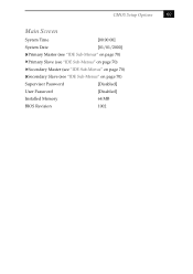
CMOS Setup Options 69 Main Screen System Time [00:00:00] System Date [01/01/2000] Primary Master (see "IDE Sub-Menus" on page 70) Primary Slave (see "IDE Sub-Menus" on page 70) Secondary Master (see "IDE Sub-Menus" on page 70) Secondary Slave (see "IDE Sub-Menus" on page 70) Supervisor Password [Disabled] User Password [Disabled] Installed Memory 64 MB BIOS Revision 1002
CMOS Setup Options 69 Main Screen System Time [00:00:00] System Date [01/01/2000] Primary Master (see "IDE Sub-Menus" on page 70) Primary Slave (see "IDE Sub-Menus" on page 70) Secondary Master (see "IDE Sub-Menus" on page 70) Secondary Slave (see "IDE Sub-Menus" on page 70) Supervisor Password [Disabled] User Password [Disabled] Installed Memory 64 MB BIOS Revision 1002

System Reference Manual (primary manual)
Page 87
Chapter 8 Miscellaneous Technical Information This chapter contains information on the following subjects: ❑ User and Supervisor password ❑ Beep code error messages ❑ PCI configuration status and error messages ❑ DMA channel assignments ❑ IRQ assignments ❑ System I/O address map ❑ Memory map ❑ PCI configuration space map 75
Chapter 8 Miscellaneous Technical Information This chapter contains information on the following subjects: ❑ User and Supervisor password ❑ Beep code error messages ❑ PCI configuration status and error messages ❑ DMA channel assignments ❑ IRQ assignments ❑ System I/O address map ❑ Memory map ❑ PCI configuration space map 75

System Reference Manual (primary manual)
Page 90
... Cleared CMOS Data Invalid, CMOS Cleared Parallel Port Resource Conflict PCI Error Log is Full PCI I/O Port Conflict PCI IRQ Conflict PCI Memory Conflict Primary Boot Device Not Found Primary IDE Controller Resource Conflict Primary Input Device Not Found Primary Output Device Not Found Secondary IDE Controller... in use. The secondary IDE controller has requested a resource that may appear on your system from time to a CMOS checksum error. 78 VAIO® Reference Manual PCI Configuration Status and Error Messages The following is a list of status and error messages that is already in use....
... Cleared CMOS Data Invalid, CMOS Cleared Parallel Port Resource Conflict PCI Error Log is Full PCI I/O Port Conflict PCI IRQ Conflict PCI Memory Conflict Primary Boot Device Not Found Primary IDE Controller Resource Conflict Primary Input Device Not Found Primary Output Device Not Found Secondary IDE Controller... in use. The secondary IDE controller has requested a resource that may appear on your system from time to a CMOS checksum error. 78 VAIO® Reference Manual PCI Configuration Status and Error Messages The following is a list of status and error messages that is already in use....

System Reference Manual (primary manual)
Page 91
The Microsoft® Windows® Millenium Edition operating system reassigns resources to best meet the needs of a particular configuration. Miscellaneous Technical Information 79 DMA Channel Assignments This shows the factory default values. DMA Channel 2 4 Default Assignment Standard diskette controller Direct memory access controller
The Microsoft® Windows® Millenium Edition operating system reassigns resources to best meet the needs of a particular configuration. Miscellaneous Technical Information 79 DMA Channel Assignments This shows the factory default values. DMA Channel 2 4 Default Assignment Standard diskette controller Direct memory access controller
System Reference Manual (primary manual)
Page 94
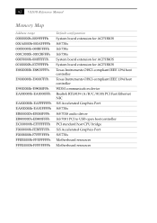
82 VAIO® Reference Manual Memory Map Address range 00000000h-0009FFFFh 000A0000h-000AFFFFh 000B0000h-000BFFFFh 000C0000h-000CBFFFh 000F0000h-000FFFFFh 00100000h-037FFFFFh E8800000h-E8803FFFh E9000000h-E90007FFh E9800000h-E98000FFh EA000000h-EA0000FFh EA800000h-EAFFFFFFh ...
82 VAIO® Reference Manual Memory Map Address range 00000000h-0009FFFFh 000A0000h-000AFFFFh 000B0000h-000BFFFFh 000C0000h-000CBFFFh 000F0000h-000FFFFFh 00100000h-037FFFFFh E8800000h-E8803FFFh E9000000h-E90007FFh E9800000h-E98000FFh EA000000h-EA0000FFh EA800000h-EAFFFFFFh ...

System Reference Manual (primary manual)
Page 97
...33 MHz zero wait state 4 PCI slots (2 open) Memory Modules (DIMMs) Installed memory Maximum memory Voltage Pins SDRAM type 64 MB PC-133 SDRAM (133 MHz) 512 Mbytes (256 Mbytes in each socket) 3.3 V memory only 168-pins with gold-plated contacts PC-133, ...60 ns, unrestricted CAS latency 2, unbuffered, Intel 4-clock, 64 bits (non-ECC) 85 Processor 800 MHz* AMD Duron™ processor * MHz denotes microprocessor internal clock speed. Chapter 9 Specifications This chapter describes the technical specifications for the Sony PCV-J150 computer...
...33 MHz zero wait state 4 PCI slots (2 open) Memory Modules (DIMMs) Installed memory Maximum memory Voltage Pins SDRAM type 64 MB PC-133 SDRAM (133 MHz) 512 Mbytes (256 Mbytes in each socket) 3.3 V memory only 168-pins with gold-plated contacts PC-133, ...60 ns, unrestricted CAS latency 2, unbuffered, Intel 4-clock, 64 bits (non-ECC) 85 Processor 800 MHz* AMD Duron™ processor * MHz denotes microprocessor internal clock speed. Chapter 9 Specifications This chapter describes the technical specifications for the Sony PCV-J150 computer...
System Reference Manual (primary manual)
Page 98
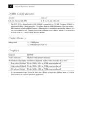
...SiS730S Video memory Shared with 64 MB. Does not support EDO memory or buffered DIMM memory. DIMMs must be single- Supports SDRAM memory. 86 VAIO® Reference Manual DIMM Configurations DIMM1* 0, 8, 16, 32, 64, 128, 256 DIMM2* 0, 8, 16, 32, 64, 128, 256 * The PCV-J150 is shipped with system memory Resolution (...-interlaced 256 colors (8 bits) Up to 1600 x 1200 at 75 Hz or lower refresh rate for video playback applications. Memory can vary between sockets. Computer SDRAM is expandable to use 1024x768 True color (24 bits) or High color (16 bits) when at 75 Hz non...
...SiS730S Video memory Shared with 64 MB. Does not support EDO memory or buffered DIMM memory. DIMMs must be single- Supports SDRAM memory. 86 VAIO® Reference Manual DIMM Configurations DIMM1* 0, 8, 16, 32, 64, 128, 256 DIMM2* 0, 8, 16, 32, 64, 128, 256 * The PCV-J150 is shipped with system memory Resolution (...-interlaced 256 colors (8 bits) Up to 1600 x 1200 at 75 Hz or lower refresh rate for video playback applications. Memory can vary between sockets. Computer SDRAM is expandable to use 1024x768 True color (24 bits) or High color (16 bits) when at 75 Hz non...
System Reference Manual (primary manual)
Page 100
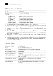
88 VAIO® Reference Manual Drives and Controllers Drive Diskette drive CD-RW drive* CD-RW read† CD-RW write‡ CD-R read** CD-R write†&#.../s). System BIOS Make and model ROM Passwords Recovery boot block Power management Advanced features Plug and Play devices Special features Award-based 2Mbit CMOS Flash memory User and supervisor passwords supported Supported APM 1.2 ACPI-1.0 compliant hardware for use with APM and PNP BIOS APIs Supported with steerable DMA channels and interrupts...
88 VAIO® Reference Manual Drives and Controllers Drive Diskette drive CD-RW drive* CD-RW read† CD-RW write‡ CD-R read** CD-R write†&#.../s). System BIOS Make and model ROM Passwords Recovery boot block Power management Advanced features Plug and Play devices Special features Award-based 2Mbit CMOS Flash memory User and supervisor passwords supported Supported APM 1.2 ACPI-1.0 compliant hardware for use with APM and PNP BIOS APIs Supported with steerable DMA channels and interrupts...


