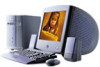
Sony PCV-J150 - Vaio Desktop Computer Support and Manuals
Get Help and Manuals for this Sony item
View All Support Options Below
Free Sony PCV-J150 manuals!
Problems with Sony PCV-J150?
Ask a Question
Free Sony PCV-J150 manuals!
Problems with Sony PCV-J150?
Ask a Question
Most Recent Sony PCV-J150 Questions

Sony Pcv-j150
My Sony Pcv-j159 is not properly working. I never used it a lot but needed to use it so I plugged it...
My Sony Pcv-j159 is not properly working. I never used it a lot but needed to use it so I plugged it...
(Posted by Darienadams 12 years ago)
Popular Sony PCV-J150 Manual Pages
System Reference Manual (primary manual) - Page 2
... software may not necessarily be identical to the terms and conditions of your Sony Service Center. Some of IBM Corporation.
Model Number: PCV-J150
Serial Number
ii All rights reserved. Financial services may not be transported or used outside the United States. This manual and the software described herein, in whole or in the space provided here...
System Reference Manual (primary manual) - Page 5
... Part 15 of Conformity
Trade Name:
SONY
Model No.:
PCV-J150
Responsible Party: Sony Electronics Inc. Operation with cables, connected to peripherals, that to which can radiate radio frequency energy and, if not installed and used to connect peripherals must accept any interference received, including interference that any changes or modifications not expressly approved in this manual...
System Reference Manual (primary manual) - Page 30
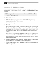
... to the BIOS settings (see "CMOS Setup Options" on page 67 for information on BIOS settings).
! Once an...Sony logo appears, press F3.
Use the left , this indicates that a sub-menu of options is another layer of options from which to select.
4 Once you reach the top level, where the menu bar appears.
5 To exit the BIOS setup utility, press ESC from the menu bar. 16 VAIO® Reference Manual...
System Reference Manual (primary manual) - Page 34

... 1-2 2-3
CMOS Clear Normal Clear OM04588.VSD
3 Reinstall the side panel (see "Replacing the Side Panel" on page 25).
20 Access to specific setup fields is stored in CMOS. No other parameters are only cleared if the checksum test returns false. The Clear CMOS mode removes the password that is controlled by a technical support or service technician.
!
System Reference Manual (primary manual) - Page 36
KY0064B.VSD 22 VAIO® Reference Manual
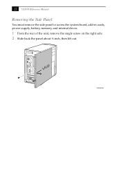
Removing the Side Panel
You must remove the side panel to access the system board, add-in cards, power supply, battery, memory, and internal drives.
1 From the rear of the unit, remove the single screw on the right side. 2 Slide back the panel about ½ inch, then lift out.
System Reference Manual (primary manual) - Page 46
32 VAIO® Reference Manual
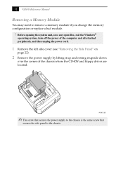
Removing a Memory Module
You may need to the chassis.
AUR001.VSD
✍ The screw that secures the power supply to the chassis is the same screw that
secures the side panel to remove a memory module if you change the memory configuration or replace a bad module.
! Before opening the system unit, save...
System Reference Manual (primary manual) - Page 48
34 VAIO® Reference Manual
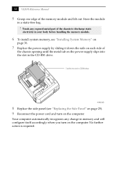
5 Grasp one edge of
the chassis opening until the metal tab on the power supply slips into slot in CD-RW drive
AUR002.VSD
8 Replace the side panel (see "Installing System Memory" on
page 36.
7 Replace the power supply by sliding it down the rails on each side of the memory module and lift out...
System Reference Manual (primary manual) - Page 49
... 8, 16, 32, 64, 128, 256
* The PCV-J150 ships with 133 MHz memory. Does not
support EDO memory or buffered DIMM memory.
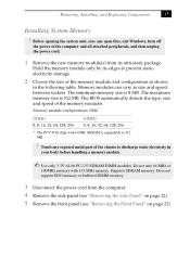
3 Disconnect the power cord from its edges to 512 MB.
! Removing, Installing, and Replacing Components
35
Installing System Memory
! Touch any open files, exit Windows, ...is 8 MB. Before opening the system unit, save any exposed metal part of the memory modules.
System Reference Manual (primary manual) - Page 50
...VAIO® Reference Manual
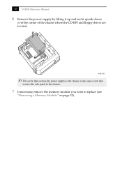
6 Remove the power supply by lifting it up and rest it upside down
over the corner of the chassis where the CD-RW and floppy drives are located. AUR001.VSD
✍ The screw that secures the power supply... to the chassis is the same screw that
secures the side panel to the chassis.
7 If necessary, remove the memory module you wish to replace (see
...
System Reference Manual (primary manual) - Page 52

38 VAIO® Reference Manual
11 Replace the power supply by sliding it down the rails on each side of
the chassis opening until the metal tab on the power supply slips into slot in the CD-RW drive. No further action is required. Your computer automatically recognizes the extra memory and will configure itself accordingly ...
System Reference Manual (primary manual) - Page 56
Disk drive holder
KY0081.VSD
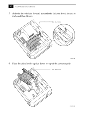
6 Place the drive holder upside down on top of the power supply. Disk drive holder
KY0081B.VSD 42 VAIO® Reference Manual
5 Slide the drive holder forward (towards the diskette drive) about a ½
inch, and then lift out.
System Reference Manual (primary manual) - Page 64
... VAIO® Reference Manual
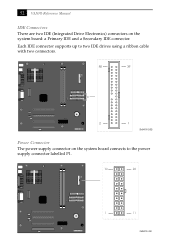
IDE Connectors There are two IDE (Integrated Drive Electronics) connectors on the system board connects to two IDE drives using a ribbon cable with two connectors.
40
39
2
1
OM04701G.VSD
Power Connector
The power supply connector on the system board: a Primary IDE and a Secondary IDE connector. Each IDE connector supports up to the power supply...
System Reference Manual (primary manual) - Page 81
CMOS Setup Options
69
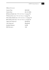
Main Screen
System Time
[00:00:00]
System Date
[01/01/2000]
Primary Master (see "IDE Sub-Menus" on page 70)
Primary Slave (see "IDE Sub-Menus" on page 70)
Secondary Master (see "IDE Sub-Menus" on page 70)
Secondary Slave (see "IDE Sub-Menus" on page 70)
Supervisor Password
[Disabled]
User Password
[Disabled]
Installed Memory
64 MB
BIOS Revision
1002
System Reference Manual (primary manual) - Page 97

...
PCI Bus
PCI Level 2.2, 33 MHz zero wait state 4 PCI slots (2 open)
Memory Modules (DIMMs)
Installed memory Maximum memory Voltage Pins SDRAM type
64 MB PC-133 SDRAM (133 MHz) 512 Mbytes (256 Mbytes ...MHz* AMD Duron™ processor
* MHz denotes microprocessor internal clock speed.
Chapter 9 Specifications
This chapter describes the technical specifications for the Sony PCV-J150 computer.
System Reference Manual (primary manual) - Page 98
86 VAIO® Reference Manual
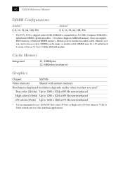
DIMM Configurations
DIMM1* 0, 8, 16, 32, 64, 128, 256
DIMM2* 0, 8, 16, 32, 64, 128, 256
* The PCV-J150 is expandable to 1600 x 1200 at 75 Hz or lower refresh rate for video playback applications. SDRAM is shipped with system memory
Resolution (displayed resolution depends on the video monitor you use 1024x768 True color...
Sony PCV-J150 Reviews
We have not received any reviews for Sony yet.