Reference Manual
Page 12
... Installing an Add-In Card 26 Removing an Add-in Card 27 Replacing the Lithium Battery 29 Installing System Memory 32 Removing a Memory Module 36 Removing a Slot Cover 38 Covering an Open I/O Slot 39 Installing a 3½" Internal Hard ... i.LINK® Card Chapter 7 - System Board Connectors 46 Front Panel Header (J25 46 Diskette Drive Connector 47 Memory Module (DIMM) Connectors 48 PCI Slot Connectors 49 IDE Connectors 50 Power Connector 50 KEYBOARD and MOUSE Connectors 51 USB... WOL Connector 61 Configuration Jumper 62 Chapter 5 - xii VAIO® Reference Manual Chapter 3 -
... Installing an Add-In Card 26 Removing an Add-in Card 27 Replacing the Lithium Battery 29 Installing System Memory 32 Removing a Memory Module 36 Removing a Slot Cover 38 Covering an Open I/O Slot 39 Installing a 3½" Internal Hard ... i.LINK® Card Chapter 7 - System Board Connectors 46 Front Panel Header (J25 46 Diskette Drive Connector 47 Memory Module (DIMM) Connectors 48 PCI Slot Connectors 49 IDE Connectors 50 Power Connector 50 KEYBOARD and MOUSE Connectors 51 USB... WOL Connector 61 Configuration Jumper 62 Chapter 5 - xii VAIO® Reference Manual Chapter 3 -
Reference Manual
Page 13
... Options Main Screen 71 Advanced Screen 73 Power Screen 79 Boot Screen 81 Exit Screen 82 Chapter 9 - Specifications Processor 93 Chipset ...93 PCI Bus ...93 Memory Modules (DIMMs 93 DIMM Configurations 94 L2 Cache ...94 Graphics ...94 Audio ...95 Communications 95 I /O Address Map 88...
... Options Main Screen 71 Advanced Screen 73 Power Screen 79 Boot Screen 81 Exit Screen 82 Chapter 9 - Specifications Processor 93 Chipset ...93 PCI Bus ...93 Memory Modules (DIMMs 93 DIMM Configurations 94 L2 Cache ...94 Graphics ...94 Audio ...95 Communications 95 I /O Address Map 88...

Reference Manual
Page 36
KY0064B.VSD 22 VAIO® Reference Manual Removing the Side Panel You must remove the side panel to access the system board, add-in cards, power supply, battery, memory, and internal drives. 1 From the rear of the unit, remove the single screw on the right side. 2 Slide back the panel about ½ inch, then lift out.
KY0064B.VSD 22 VAIO® Reference Manual Removing the Side Panel You must remove the side panel to access the system board, add-in cards, power supply, battery, memory, and internal drives. 1 From the rear of the unit, remove the single screw on the right side. 2 Slide back the panel about ½ inch, then lift out.
Reference Manual
Page 43
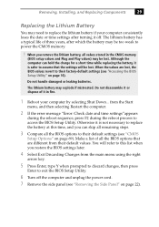
... the BIOS options that the settings will refer to this time, and you remove the lithium battery, all the BIOS options to power the CMOS memory. ! You will be too weak to their default settings (see "CMOS Setup Options" on page 69). from their default values. Removing, Installing, ... settings (see "Accessing the BIOS Setup Utility" on page 16). When the values are different from the Start menu, and then selecting Restart the computer. 2 If the error message "Error: Check date and time settings"appears during the reboot sequence, press F2 during the reboot process to exit the...
... the BIOS options that the settings will refer to this time, and you remove the lithium battery, all the BIOS options to power the CMOS memory. ! You will be too weak to their default settings (see "CMOS Setup Options" on page 69). from their default values. Removing, Installing, ... settings (see "Accessing the BIOS Setup Utility" on page 16). When the values are different from the Start menu, and then selecting Restart the computer. 2 If the error message "Error: Check date and time settings"appears during the reboot sequence, press F2 during the reboot process to exit the...
Reference Manual
Page 46
... in diagram). The minimum memory size is 256 MB. Memory module configurations (MB)* DIMM1 0, 8, 16, 32, 64, 128 DIMM2 0, 8, 16, 32, 64, 128 * The PCV-J100 ships with 100 MHz memory. Does not support EDO memory or buffered DIMM memory. 4 Disconnect the power cord from the computer. 5 Remove the side ... memory. The maximum memory size is 8 MB. Hold the memory module only by its anti-static package. Do not mix 66 MHz memory with 64 MB. 32 VAIO® Reference Manual Installing System Memory ! Touch any open files, exit Windows, turn off the power of the computer and...
... in diagram). The minimum memory size is 256 MB. Memory module configurations (MB)* DIMM1 0, 8, 16, 32, 64, 128 DIMM2 0, 8, 16, 32, 64, 128 * The PCV-J100 ships with 100 MHz memory. Does not support EDO memory or buffered DIMM memory. 4 Disconnect the power cord from the computer. 5 Remove the side ... memory. The maximum memory size is 8 MB. Hold the memory module only by its anti-static package. Do not mix 66 MHz memory with 64 MB. 32 VAIO® Reference Manual Installing System Memory ! Touch any open files, exit Windows, turn off the power of the computer and...

Reference Manual
Page 48
Press down here Handles Pin 1 side DIMM2 DIMM1 Memory module (DIMM) 1 10 Carefully but firmly insert the edge of the module into the socket. ✍ Gently push the power supply cables and ribbon cables .... ✍ When the module is fully seated, the handles on the socket. If the handles are straight up and locked into place. 34 VAIO® Reference Manual 9 Align the memory module over the appropriate socket, noting the location of pin 1 on the module and pin 1 on each side are not totally straight...
Press down here Handles Pin 1 side DIMM2 DIMM1 Memory module (DIMM) 1 10 Carefully but firmly insert the edge of the module into the socket. ✍ Gently push the power supply cables and ribbon cables .... ✍ When the module is fully seated, the handles on the socket. If the handles are straight up and locked into place. 34 VAIO® Reference Manual 9 Align the memory module over the appropriate socket, noting the location of pin 1 on the module and pin 1 on each side are not totally straight...

Reference Manual
Page 49
Removing, Installing, and Replacing Components 35 12 Slide the diskette drive back in and replace the screw that secures the diskette drive to the chassis. 13 Replace the front panel (see "Replacing the Front Panel" on page 24). 14 Replace the side panel (see "Replacing the Side Panel" on page 25). 15 Reconnect the power cord and turn on the computer. Your computer automatically recognizes the extra memory and will configure itself accordingly when you turn on the computer. No further action is required.
Removing, Installing, and Replacing Components 35 12 Slide the diskette drive back in and replace the screw that secures the diskette drive to the chassis. 13 Replace the front panel (see "Replacing the Front Panel" on page 24). 14 Replace the side panel (see "Replacing the Side Panel" on page 25). 15 Reconnect the power cord and turn on the computer. Your computer automatically recognizes the extra memory and will configure itself accordingly when you turn on the computer. No further action is required.
Reference Manual
Page 50
36 VAIO® Reference Manual Removing a Memory Module You may need to the chassis and slide the diskette drive out about two inches (the attached cables limit this distance). 1 VOY001.VSD Before opening the system unit, save any open files, exit the Windows® operating system, turn off the power of the computer and...
36 VAIO® Reference Manual Removing a Memory Module You may need to the chassis and slide the diskette drive out about two inches (the attached cables limit this distance). 1 VOY001.VSD Before opening the system unit, save any open files, exit the Windows® operating system, turn off the power of the computer and...

Reference Manual
Page 51
Touch any exposed metal part of the chassis to eject the module from its socket. Store the module in your body before handling the memory module. Removing, Installing, and Replacing Components 37 4 Locate the memory module you reach inside the system to access the module connector. 6 Grasp one edge of the memory module and lift out. KY0073.VSD 5 Push down the handle on each side of the memory module to discharge static electricity in a static-free bag. ! Push out Handles KY0042.VS ✍ Gently push the power supply cables and ribbon cables aside as you wish to remove.
Touch any exposed metal part of the chassis to eject the module from its socket. Store the module in your body before handling the memory module. Removing, Installing, and Replacing Components 37 4 Locate the memory module you reach inside the system to access the module connector. 6 Grasp one edge of the memory module and lift out. KY0073.VSD 5 Push down the handle on each side of the memory module to discharge static electricity in a static-free bag. ! Push out Handles KY0042.VS ✍ Gently push the power supply cables and ribbon cables aside as you wish to remove.

Reference Manual
Page 59
Keyboard, Mouse USB1/2 USB Header (not used) Serial, Monitor, Printer Mic In, Line In, Line Out, Game CD-In (to CD-RW drive) Aux-In CPU CPU Fan Memory Slot 4 (PCI) Slot 3 (PCI) Slot 2 (PCI) Slot 1 (PCI) CMOS Clear Normal 1-2 Clear 2-3 Power Supply Fan Power Supply Secondary IDE Primary IDE Diskette Wake on the system board. Chapter 4 System Board This chapter identifies each component on the system board and provides a detailed description of each connector, jumper, and switch on LAN (to Ethernet card) Front panel header Battery OM04581.VSD 45
Keyboard, Mouse USB1/2 USB Header (not used) Serial, Monitor, Printer Mic In, Line In, Line Out, Game CD-In (to CD-RW drive) Aux-In CPU CPU Fan Memory Slot 4 (PCI) Slot 3 (PCI) Slot 2 (PCI) Slot 1 (PCI) CMOS Clear Normal 1-2 Clear 2-3 Power Supply Fan Power Supply Secondary IDE Primary IDE Diskette Wake on the system board. Chapter 4 System Board This chapter identifies each component on the system board and provides a detailed description of each connector, jumper, and switch on LAN (to Ethernet card) Front panel header Battery OM04581.VSD 45

Reference Manual
Page 62
The side with pin 1 has a small "1" to orient a DIMM correctly in the DIMM connector (a small triangle on the connector indicates pin 1). Memory module (DIMM) 1 Indicates pin 1 OM04908B.VSD 48 VAIO® Reference Manual Memory Module (DIMM) Connectors DIMM1 DIMM2 OM04710A.VSD Both sides of pin 1. Be sure to the left of each Dual Inline Memory Module (DIMM) look very similar.
The side with pin 1 has a small "1" to orient a DIMM correctly in the DIMM connector (a small triangle on the connector indicates pin 1). Memory module (DIMM) 1 Indicates pin 1 OM04908B.VSD 48 VAIO® Reference Manual Memory Module (DIMM) Connectors DIMM1 DIMM2 OM04710A.VSD Both sides of pin 1. Be sure to the left of each Dual Inline Memory Module (DIMM) look very similar.
Reference Manual
Page 85
...) Language [English] Supervisor Password [Disabled] User Password [Disabled] Halt On [All but Keyboard] All but Disk All but Disk/Keyboard All Errors No Error Installed Memory 63 MB Legacy Diskette B [None] 360K, 5.25 in. 1.2M, 5.25 in. 720K, 3.5 in. 1.44M, 3.5 in. 2.88M, 3.5 in.
...) Language [English] Supervisor Password [Disabled] User Password [Disabled] Halt On [All but Keyboard] All but Disk All but Disk/Keyboard All Errors No Error Installed Memory 63 MB Legacy Diskette B [None] 360K, 5.25 in. 1.2M, 5.25 in. 720K, 3.5 in. 1.44M, 3.5 in. 2.88M, 3.5 in.
Reference Manual
Page 87
... CPU Level 2 Cache ECC Check [Disabled] Enabled BIOS Update [Enabled] Disabled PS/2 Mouse Function Control [Auto] Enabled USB Legacy Support [Auto] Disabled Enabled OS/2 Onboard Memory > 64M [Disabled] Enabled Chip Configuration (see "Chip Configuration Sub-Menu" on page 74) I/O Device Configuration (see "I/O Device Configuration Sub-Menu" on page 75) PCI Configuration...
... CPU Level 2 Cache ECC Check [Disabled] Enabled BIOS Update [Enabled] Disabled PS/2 Mouse Function Control [Auto] Enabled USB Legacy Support [Auto] Disabled Enabled OS/2 Onboard Memory > 64M [Disabled] Enabled Chip Configuration (see "Chip Configuration Sub-Menu" on page 74) I/O Device Configuration (see "I/O Device Configuration Sub-Menu" on page 75) PCI Configuration...

Reference Manual
Page 88
74 VAIO® Reference Manual Chip Configuration Sub-Menu SDRAM Configuration SDRAM CAS Latency SDRAM RAS to CAS Delay SDRAM RAS Precharge Time SDRAM Cycle Time (Tras, Trc) SDRAM Page Closing Policy CPU Latency Timer On-board VGA Display Cache Paging Mode Video Memory Cache Mode Memory Hole At 15M-16M PCI 2.1 Support High...
74 VAIO® Reference Manual Chip Configuration Sub-Menu SDRAM Configuration SDRAM CAS Latency SDRAM RAS to CAS Delay SDRAM RAS Precharge Time SDRAM Cycle Time (Tras, Trc) SDRAM Page Closing Policy CPU Latency Timer On-board VGA Display Cache Paging Mode Video Memory Cache Mode Memory Hole At 15M-16M PCI 2.1 Support High...

Reference Manual
Page 97
Chapter 9 Miscellaneous Technical Information This chapter contains information on the following subjects: ❑ User and Supervisor password ❑ Beep code error messages ❑ PCI configuration status and error messages ❑ DMA channel assignments ❑ IRQ assignments ❑ System I/O address map ❑ Memory map ❑ PCI configuration space map 83
Chapter 9 Miscellaneous Technical Information This chapter contains information on the following subjects: ❑ User and Supervisor password ❑ Beep code error messages ❑ PCI configuration status and error messages ❑ DMA channel assignments ❑ IRQ assignments ❑ System I/O address map ❑ Memory map ❑ PCI configuration space map 83

Reference Manual
Page 100
...is already in use . Serial port 1 has requested a resource that is already in use . This message is already in use . 86 VAIO® Reference Manual PCI Configuration Status and Error Messages The following is a list of status and error messages that may appear on your system ...Cleared CMOS Data Invalid, CMOS Cleared Parallel Port Resource Conflict PCI Error Log is Full PCI I/O Port Conflict PCI IRQ Conflict PCI Memory Conflict Primary Boot Device Not Found Primary IDE Controller Resource Conflict Primary Input Device Not Found Primary Output Device Not Found Secondary IDE ...
...is already in use . Serial port 1 has requested a resource that is already in use . This message is already in use . 86 VAIO® Reference Manual PCI Configuration Status and Error Messages The following is a list of status and error messages that may appear on your system ...Cleared CMOS Data Invalid, CMOS Cleared Parallel Port Resource Conflict PCI Error Log is Full PCI I/O Port Conflict PCI IRQ Conflict PCI Memory Conflict Primary Boot Device Not Found Primary IDE Controller Resource Conflict Primary Input Device Not Found Primary Output Device Not Found Secondary IDE ...

Reference Manual
Page 101
The Microsoft® Windows® 98 Second Edition operating system reassigns resources to best meet the needs of a particular configuration. DMA Channel 2 4 Default Assignment Standard diskette controller Direct memory access controller Miscellaneous Technical Information 87 DMA Channel Assignments This shows the factory default values.
The Microsoft® Windows® 98 Second Edition operating system reassigns resources to best meet the needs of a particular configuration. DMA Channel 2 4 Default Assignment Standard diskette controller Direct memory access controller Miscellaneous Technical Information 87 DMA Channel Assignments This shows the factory default values.
Reference Manual
Page 104
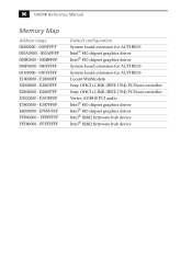
...174; 810 chipset graphics driver System board extension for ACPI BIOS System board extension for ACPI BIOS Lucent WinModem Sony OHCI i.LINK (IEEE 1394) PCI host controller Sony OHCI i.LINK (IEEE 1394) PCI host controller Vortex AU8810 PCI audio Intel® 810 chipset graphics driver ...Intel® 810 chipset graphics driver Intel® 82802 firmware hub device Intel® 82802 firmware hub device E28007FF E3000000 - FFBFFFFF FFF80000 - 90 VAIO® Reference Manual Memory ...
...174; 810 chipset graphics driver System board extension for ACPI BIOS System board extension for ACPI BIOS Lucent WinModem Sony OHCI i.LINK (IEEE 1394) PCI host controller Sony OHCI i.LINK (IEEE 1394) PCI host controller Vortex AU8810 PCI audio Intel® 810 chipset graphics driver ...Intel® 810 chipset graphics driver Intel® 82802 firmware hub device Intel® 82802 firmware hub device E28007FF E3000000 - FFBFFFFF FFF80000 - 90 VAIO® Reference Manual Memory ...
Reference Manual
Page 107
...2.2, 33 MHz zero wait state 4 PCI slots (1 open) Memory Modules (DIMMs) Installed memory Maximum memory Voltage Pins SDRAM type 64 Mbytes PC-100 SDRAM (100 MHz) 256 Mbytes (128Mbytes in each socket) 3.3 V memory only 168-pins with 66 MHz FSB) * MHz denotes microprocessor... internal clock speed. Other factors may affect application performance. Chapter 10 Specifications This chapter describes the technical specifications for the Sony PCV-J100 computer. Processor 600 MHz* Intel Celeron™...
...2.2, 33 MHz zero wait state 4 PCI slots (1 open) Memory Modules (DIMMs) Installed memory Maximum memory Voltage Pins SDRAM type 64 Mbytes PC-100 SDRAM (100 MHz) 256 Mbytes (128Mbytes in each socket) 3.3 V memory only 168-pins with 66 MHz FSB) * MHz denotes microprocessor... internal clock speed. Other factors may affect application performance. Chapter 10 Specifications This chapter describes the technical specifications for the Sony PCV-J100 computer. Processor 600 MHz* Intel Celeron™...
Reference Manual
Page 108
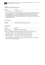
... module. L2 Cache Installed 128 KB of Advanced Transfer Cache Graphics Chipset Intel 810 Video memory Shared with 64 MB. Computer SDRAM is shipped with system memory Resolution (displayed resolution depends on the video monitor you use)* True color (24 bits)...either socket. Supports SDRAM memory. Memory size can be single- Does not support EDO memory or buffered DIMM memory. DIMMs can vary between sockets. 94 VAIO® Reference Manual DIMM Configurations DIMM1* 0, 8, 16, 32, 64, 128 DIMM2* 0, 8, 16, 32, 64, 128 * The PCV-J100 is unbuffered DIMM, specification...
... module. L2 Cache Installed 128 KB of Advanced Transfer Cache Graphics Chipset Intel 810 Video memory Shared with 64 MB. Computer SDRAM is shipped with system memory Resolution (displayed resolution depends on the video monitor you use)* True color (24 bits)...either socket. Supports SDRAM memory. Memory size can be single- Does not support EDO memory or buffered DIMM memory. DIMMs can vary between sockets. 94 VAIO® Reference Manual DIMM Configurations DIMM1* 0, 8, 16, 32, 64, 128 DIMM2* 0, 8, 16, 32, 64, 128 * The PCV-J100 is unbuffered DIMM, specification...


