
Operating Instructions
Page 3
...that any interference received, including interference that may cause harmful interference to Subpart B of Part 15 of the FCC Rules. The shielded interface cable supplied with the limits for a digital device pursuant to radio communications. Note: This equipment has been tested and found to ..., may cause undesired operation. Consult the dealer or an experienced radio/TV technician for a Class B digital device, pursuant to operate this manual could void your authority to Part 15 of the following two conditions: (1) This device may not cause harmful interference, and (2) this...
...that any interference received, including interference that may cause harmful interference to Subpart B of Part 15 of the FCC Rules. The shielded interface cable supplied with the limits for a digital device pursuant to radio communications. Note: This equipment has been tested and found to ..., may cause undesired operation. Consult the dealer or an experienced radio/TV technician for a Class B digital device, pursuant to operate this manual could void your authority to Part 15 of the following two conditions: (1) This device may not cause harmful interference, and (2) this...
Operating Instructions
Page 5
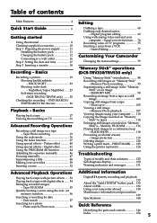
...mode 36 Using the fader function 37 Using special effects - Insert Editing 77 Customizing Your Camcorder Changing the menu settings 79 "Memory Stick" operations (DCR-TRV330/TRV530 only) Using "Memory Stick"-introduction .......... 88 Recording still images on a tape - Photo save 105 Viewing a still image - Photo search/Photo scan 58 Digital8...12 Connecting to tapes 114 Enlarging still images recorded on an image - NightShot/Super NightShot ...... 23 Self-timer recording (DCR-TRV330/TRV530 only) ....... 25 Checking the recording - Digital effect 41 Using the PROGRAM AE...
...mode 36 Using the fader function 37 Using special effects - Insert Editing 77 Customizing Your Camcorder Changing the menu settings 79 "Memory Stick" operations (DCR-TRV330/TRV530 only) Using "Memory Stick"-introduction .......... 88 Recording still images on a tape - Photo save 105 Viewing a still image - Photo search/Photo scan 58 Digital8...12 Connecting to tapes 114 Enlarging still images recorded on an image - NightShot/Super NightShot ...... 23 Self-timer recording (DCR-TRV330/TRV530 only) ....... 25 Checking the recording - Digital effect 41 Using the PROGRAM AE...

Operating Instructions
Page 13
When the battery pack is charged fully The LCD backlight of Sony Corporation. The battery pack is "InfoLITHIUM"? If the power may cause a ...battery remaining indicator is turned off the power. Until your camcorder calculates the actual remaining battery time "- - - - min" appears in the following cases: - TM SERIES 13 Your camcorder operates only with the viewfinder. Remaining battery time indicator ... the wall outlet as soon as battery consumption with the metal parts of the DC plug of the AC power adaptor. If any trouble occurs with this once a year.
When the battery pack is charged fully The LCD backlight of Sony Corporation. The battery pack is "InfoLITHIUM"? If the power may cause a ...battery remaining indicator is turned off the power. Until your camcorder calculates the actual remaining battery time "- - - - min" appears in the following cases: - TM SERIES 13 Your camcorder operates only with the viewfinder. Remaining battery time indicator ... the wall outlet as soon as battery consumption with the metal parts of the DC plug of the AC power adaptor. If any trouble occurs with this once a year.

Operating Instructions
Page 18
... noise may appear when you play back the tape on other camcorders (including other DCR-TRV230/TRV330/TRV530). •The cassette compartment may cause malfunction. •Your camcorder records pictures in the Digital8 system. • The recording time when you press any part of the cassette to play back standard 8 tape on this...back of the lid other than the mark. If you select the LP mode in the menu settings, 3/4 of indicated time on Hi8 tape. •If you use standard 8 tape, be closed when you use your camcorder is half of the arrow and open the lid. Notes •Do...
... noise may appear when you play back the tape on other camcorders (including other DCR-TRV230/TRV330/TRV530). •The cassette compartment may cause malfunction. •Your camcorder records pictures in the Digital8 system. • The recording time when you press any part of the cassette to play back standard 8 tape on this...back of the lid other than the mark. If you select the LP mode in the menu settings, 3/4 of indicated time on Hi8 tape. •If you use standard 8 tape, be closed when you use your camcorder is half of the arrow and open the lid. Notes •Do...

Operating Instructions
Page 51
... To change , then press the SEL/PUSH EXEC dial. Advanced Recording Operations 51 Making your camcorder does not automatically turn it to delete the title. The last character is erased. Enter the... new title as desired. If you want to enter characters in the standby mode while a cassette is in memory. The characters you have stored In step 3, select CUSTOM1 SET or... To enter a space Select [Z& ?!], then select the blank part. We recommend setting the POWER switch to return To erase a character Select [C]. The last character is erased.
... To change , then press the SEL/PUSH EXEC dial. Advanced Recording Operations 51 Making your camcorder does not automatically turn it to delete the title. The last character is erased. Enter the... new title as desired. If you want to enter characters in the standby mode while a cassette is in memory. The characters you have stored In step 3, select CUSTOM1 SET or... To enter a space Select [Z& ?!], then select the blank part. We recommend setting the POWER switch to return To erase a character Select [C]. The last character is erased.
Operating Instructions
Page 71
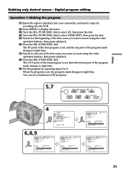
.../PUSH EXEC dial. You can set , the program mark changes to 8. The IN point of the first program is set , and the top part of the program mark changes to light blue. (7) Search for the beginning of 20 programs. 5,7 REW PLAY FF STOP PAUSE REC 4 OTHERS BEEP...set , then the bottom part of the first scene you want to insert using the video operation buttons, then pause playback. (8) Press the SEL/PUSH EXEC dial. Editing Dubbing only desired scenes - Digital program editing Operation 1: Making the program (1) Insert the tape for playback into your camcorder, and insert a tape...
.../PUSH EXEC dial. You can set , the program mark changes to 8. The IN point of the first program is set , and the top part of the program mark changes to light blue. (7) Search for the beginning of 20 programs. 5,7 REW PLAY FF STOP PAUSE REC 4 OTHERS BEEP...set , then the bottom part of the first scene you want to insert using the video operation buttons, then pause playback. (8) Press the SEL/PUSH EXEC dial. Editing Dubbing only desired scenes - Digital program editing Operation 1: Making the program (1) Insert the tape for playback into your camcorder, and insert a tape...
Operating Instructions
Page 88
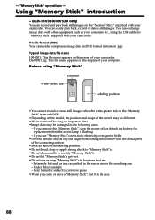
...8226;Depending on the model, the position and shape of the connecting section. •Stick its case. 88 On file format (JPEG) Your camcorder compresses image data in the sun or under the scorching sun - Typical image data file name 100-0001: This file name appears on the display... - You can record and play back, record or delete still images. If you carry or store a "Memory Stick", put it in locations that are: - Using "Memory Stick"-introduction - DCR-TRV330/TRV530 only You can exchange image data with the metal parts of the switch may be different. •We recommend backing...
...8226;Depending on the model, the position and shape of the connecting section. •Stick its case. 88 On file format (JPEG) Your camcorder compresses image data in the sun or under the scorching sun - Typical image data file name 100-0001: This file name appears on the display... - You can record and play back, record or delete still images. If you carry or store a "Memory Stick", put it in locations that are: - Using "Memory Stick"-introduction - DCR-TRV330/TRV530 only You can exchange image data with the metal parts of the switch may be different. •We recommend backing...
Operating Instructions
Page 99
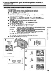
... on a tape Before operation •Insert a Hi8 /Digital8 tape for recording into your camcorder. •Insert a "Memory Stick" is recorded still images into your camcorder. (1) Set the POWER switch to CAMERA. (2) Press MEMORY MIX in the standby mode. MEMORY MIX Recording superimposed images on an image - To... scheme of the area in the moving image which is to be swapped with a still image M. CHROM 100-0021 Still image 3 4 M. The still image is superimposed on the lower part of the area in the still image which is to be swapped with a moving image M. The color (blue) ...
... on a tape Before operation •Insert a Hi8 /Digital8 tape for recording into your camcorder. •Insert a "Memory Stick" is recorded still images into your camcorder. (1) Set the POWER switch to CAMERA. (2) Press MEMORY MIX in the standby mode. MEMORY MIX Recording superimposed images on an image - To... scheme of the area in the moving image which is to be swapped with a still image M. CHROM 100-0021 Still image 3 4 M. The still image is superimposed on the lower part of the area in the still image which is to be swapped with a moving image M. The color (blue) ...

Operating Instructions
Page 101
...M. LUMI y C. CHROM 100-0021 Still image 3 4 M. The mode changes as a thumbnail image. (3) Press MEMORY+/- The still image is set to the left position. (2) Press MEMORY MIX in the still image which is recorded still images into your camcorder. (1) Set the POWER switch to MEMORY. Superimposing a still image in the moving image. (6) ... with a still image The fewer bars there are on the moving image which is to be swapped with a moving image C. LUMI - The color (blue) scheme of the area in the "Memory Stick" on the lower part of the area in the standby mode. To see...
...M. LUMI y C. CHROM 100-0021 Still image 3 4 M. The mode changes as a thumbnail image. (3) Press MEMORY+/- The still image is set to the left position. (2) Press MEMORY MIX in the still image which is recorded still images into your camcorder. (1) Set the POWER switch to MEMORY. Superimposing a still image in the moving image. (6) ... with a still image The fewer bars there are on the moving image which is to be swapped with a moving image C. LUMI - The color (blue) scheme of the area in the "Memory Stick" on the lower part of the area in the standby mode. To see...

Operating Instructions
Page 142
...AC power adaptor • Unplug the unit from AM receivers and video equipment. If this function, dub the image into your Sony VAIO. To use , particularly during use a new Hi8 /Digital8 tape. • When inputting the image recorded by the plug. Never pull the power cord itself. • Do not ...surface - Extremely hot or cold - Vibrating About care and storage of the lens • Wipe the surface of the lens clean with the metal parts of DVgate motion doesn't work. When there are not using the unit for a long time. 142 To prevent mold from coming into your computer...
...AC power adaptor • Unplug the unit from AM receivers and video equipment. If this function, dub the image into your Sony VAIO. To use , particularly during use a new Hi8 /Digital8 tape. • When inputting the image recorded by the plug. Never pull the power cord itself. • Do not ...surface - Extremely hot or cold - Vibrating About care and storage of the lens • Wipe the surface of the lens clean with the metal parts of DVgate motion doesn't work. When there are not using the unit for a long time. 142 To prevent mold from coming into your computer...
Operating Instructions
Page 145
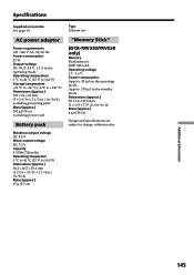
...to +140 °F) Dimensions (approx.) 125 × 39 × 62 mm (5 × 1 9/16 × 2 1/2 in. ) (w/h/d) excluding projecting parts Mass (approx.) 280 g (9.8 oz) excluding power cord Battery pack Maximun output voltage DC 8.4 V Mean output voltage DC 7.2 V Capacity 5.0 Wh (700 mAh... (w/h/d) Mass (approx.) 65 g (2.3 oz) Type Lithium ion "Memory Stick" (DCR-TRV330/TRV530 only) Memory Flash memory 4MB: MSA-4A Operating voltage 2.7 - 3.6 V Power consumption Approx. 45 mA in the operating mode Approx. 130 µA in the standby mode Dimensions (approx.) 50 × 2.8 × 21.5 mm (2 × 1/8...
...to +140 °F) Dimensions (approx.) 125 × 39 × 62 mm (5 × 1 9/16 × 2 1/2 in. ) (w/h/d) excluding projecting parts Mass (approx.) 280 g (9.8 oz) excluding power cord Battery pack Maximun output voltage DC 8.4 V Mean output voltage DC 7.2 V Capacity 5.0 Wh (700 mAh... (w/h/d) Mass (approx.) 65 g (2.3 oz) Type Lithium ion "Memory Stick" (DCR-TRV330/TRV530 only) Memory Flash memory 4MB: MSA-4A Operating voltage 2.7 - 3.6 V Power consumption Approx. 45 mA in the operating mode Approx. 130 µA in the standby mode Dimensions (approx.) 50 × 2.8 × 21.5 mm (2 × 1/8...
Operating Instructions
Page 146
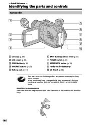
... strap Attach the shoulder strap supplied with this product is a genuine accessory for the shoulder strap. 146 When purchasing Sony video products, Sony recommends that this "GENUINE VIDEO ACCESSORIES" mark. Identifying the parts and controls Camcorder 1 5 6 2 7 3 8 9 4 0 1 Lens cap (p. 19) 2 LCD screen (p. 19) 3 OPEN button (p. 19) 4 VOLUME buttons (p. 27) 5 Battery pack (p. 11) 6 BATT (battery) release...
... strap Attach the shoulder strap supplied with this product is a genuine accessory for the shoulder strap. 146 When purchasing Sony video products, Sony recommends that this "GENUINE VIDEO ACCESSORIES" mark. Identifying the parts and controls Camcorder 1 5 6 2 7 3 8 9 4 0 1 Lens cap (p. 19) 2 LCD screen (p. 19) 3 OPEN button (p. 19) 4 VOLUME buttons (p. 27) 5 Battery pack (p. 11) 6 BATT (battery) release...
Operating Instructions
Page 147
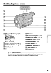
Identifying the parts and controls SUPER LASER LINK qs qd REW PLAY FF STOP PAUSE REC qa qf ql qg w; qh wa qj ws wd qk wf qa ...
Identifying the parts and controls SUPER LASER LINK qs qd REW PLAY FF STOP PAUSE REC qa qf ql qg w; qh wa qj ws wd qk wf qa ...

Operating Instructions
Page 148
button (p. 99, 107) (DCR-TRV330/TRV530 only) wl RESET button (p. 129) es ed ef e; MEMORY INDEX button (p. 108) (DCR-TRV330/TRV530 only) ea MEMORY DELETE button (p. 120) (DCR-TRV330/TRV530 only) es EXPOSURE button (p. 46) ed MEMORY MIX button (p. 99) (DCR-TRV330/TRV530 only) ef MEMORY + button (p. 99, 107) (DCR-TRV330/TRV530 only) Attaching the lens cap Attach the lens cap to the grip strap as illustrated. 148 Identifying the parts and controls wg e; wh ea wj wk wl wg EDITSEARCH buttons (p. 26) wh MEMORY PLAY button (p. 107) (DCR-TRV330/TRV530 only) wj Speaker wk MEMORY -
button (p. 99, 107) (DCR-TRV330/TRV530 only) wl RESET button (p. 129) es ed ef e; MEMORY INDEX button (p. 108) (DCR-TRV330/TRV530 only) ea MEMORY DELETE button (p. 120) (DCR-TRV330/TRV530 only) es EXPOSURE button (p. 46) ed MEMORY MIX button (p. 99) (DCR-TRV330/TRV530 only) ef MEMORY + button (p. 99, 107) (DCR-TRV330/TRV530 only) Attaching the lens cap Attach the lens cap to the grip strap as illustrated. 148 Identifying the parts and controls wg e; wh ea wj wk wl wg EDITSEARCH buttons (p. 26) wh MEMORY PLAY button (p. 107) (DCR-TRV330/TRV530 only) wj Speaker wk MEMORY -
Operating Instructions
Page 149
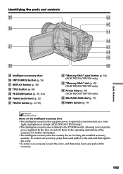
... ra PHOTO button (p. 33, 93) rs "Memory Stick" eject button (p. 90) (DCR-TRV330/TRV530 only) rd "Memory Stick" slot (p. 90) (DCR-TRV330/TRV530 only) rf Access lamp (p. 90) (DCR-TRV330/TRV530 only) rg SEL/PUSH EXEC dial (p. 79) rh MENU button (p. 79) Notes ... •The intelligent accessory shoe supplies power to optional accessories such as a video light, microphone or printer (DCR-TRV330/TRV530 only). •The intelligent accessory shoe is linked to the POWER switch, allowing you to the end... device for fixing the installed accessory securely. Identifying the parts and controls eg el r;
... ra PHOTO button (p. 33, 93) rs "Memory Stick" eject button (p. 90) (DCR-TRV330/TRV530 only) rd "Memory Stick" slot (p. 90) (DCR-TRV330/TRV530 only) rf Access lamp (p. 90) (DCR-TRV330/TRV530 only) rg SEL/PUSH EXEC dial (p. 79) rh MENU button (p. 79) Notes ... •The intelligent accessory shoe supplies power to optional accessories such as a video light, microphone or printer (DCR-TRV330/TRV530 only). •The intelligent accessory shoe is linked to the POWER switch, allowing you to the end... device for fixing the installed accessory securely. Identifying the parts and controls eg el r;
Operating Instructions
Page 150
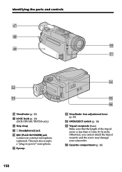
This jack also accepts a "plug-in-power" microphone. Otherwise, you cannot attach the tripod securely and the screw may damage your camcorder. i (headphones) jack ta MIC (PLUG IN POWER) jack Connect an external microphone (optional). ts Eyecup tf tg th td Viewfinder lens adjustment lever (p. 22) tf ... Tripod receptacle (base) Make sure that the length of the tripod screw is less than 6.5 mm (9/32 inch). th Cassette compartment (p. 18) 150 Identifying the parts and controls rj rk t; rl ta ts td rj Viewfinder (p. 22) rk LOCK knob (p. 19) (DCR-TRV330/TRV530 only) rl Grip strap t;
This jack also accepts a "plug-in-power" microphone. Otherwise, you cannot attach the tripod securely and the screw may damage your camcorder. i (headphones) jack ta MIC (PLUG IN POWER) jack Connect an external microphone (optional). ts Eyecup tf tg th td Viewfinder lens adjustment lever (p. 22) tf ... Tripod receptacle (base) Make sure that the length of the tripod screw is less than 6.5 mm (9/32 inch). th Cassette compartment (p. 18) 150 Identifying the parts and controls rj rk t; rl ta ts td rj Viewfinder (p. 22) rk LOCK knob (p. 19) (DCR-TRV330/TRV530 only) rl Grip strap t;

Operating Instructions
Page 151
Fastening the grip strap tl y; Identifying the parts and controls tj tk tj AUDIO/VIDEO ID-2 jack (p. 31, 60, 104) tk S VIDEO ID-2 jack (p. 31) tl DV IN/OUT jack (p. 61, 104) The ... used for Local Application Control Bus System. This jack has the same function as the jack indicated as CONTROL L or REMOTE. ya (USB) jack (p. 111) (DCR-TRV330/TRV530 only) Quick Reference Fasten the grip strap firmly. 151 LANC jack LANC stands for controlling the tape transport of video equipment and other peripherals...
Fastening the grip strap tl y; Identifying the parts and controls tj tk tj AUDIO/VIDEO ID-2 jack (p. 31, 60, 104) tk S VIDEO ID-2 jack (p. 31) tl DV IN/OUT jack (p. 61, 104) The ... used for Local Application Control Bus System. This jack has the same function as the jack indicated as CONTROL L or REMOTE. ya (USB) jack (p. 111) (DCR-TRV330/TRV530 only) Quick Reference Fasten the grip strap firmly. 151 LANC jack LANC stands for controlling the tape transport of video equipment and other peripherals...

Operating Instructions
Page 152
...sensor of the VCR with black paper. Commander modes 1, 2 and 3 are used to distinguish your camcorder from strong light sources such as on your camcorder function identically to the buttons on your camcorder. 6 1 7 2 8 9 3 0 4 5 1 PHOTO button (p. 33, 93) 2 DISPLAY button (p. 28) 3 SEARCH MODE button (p. 57, 58) 4 ./> buttons ... + and - polarities on the batteries to avoid remote control misoperation. If you use another Sony VCR in the Commander mode VTR 2. Identifying the parts and controls Remote Commander The buttons that have the same name on the Remote Commander as direct...
...sensor of the VCR with black paper. Commander modes 1, 2 and 3 are used to distinguish your camcorder from strong light sources such as on your camcorder function identically to the buttons on your camcorder. 6 1 7 2 8 9 3 0 4 5 1 PHOTO button (p. 33, 93) 2 DISPLAY button (p. 28) 3 SEARCH MODE button (p. 57, 58) 4 ./> buttons ... + and - polarities on the batteries to avoid remote control misoperation. If you use another Sony VCR in the Commander mode VTR 2. Identifying the parts and controls Remote Commander The buttons that have the same name on the Remote Commander as direct...
Operating Instructions
Page 153
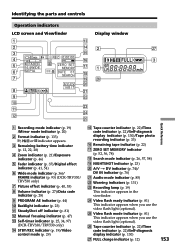
wg Video flash mode indicator (p. 81) This indicator appears when you use the video flash light (optional). Identifying the parts and controls Operation indicators LCD screen and Viewfinder Display window 1 qd 2 qf 2 wj 3 qg 4 40min SP ...Remaining battery time indicator (p. 12, 22, 28) 4 Zoom indicator (p. 21)/Exposure indicator (p. 46) 5 Fader indicator (p. 37)/Digital effect indicator (p. 41, 54) 6 Wide mode indicator (p. 36)/ FRAME indicator (p. 93) (DCR-TRV330/ TRV530 only) 7 Picture effect indicator (p. 40, 53) 8 Volume indicator (p. 27)/Data code indicator (p. 28) 9 PROGRAM...
wg Video flash mode indicator (p. 81) This indicator appears when you use the video flash light (optional). Identifying the parts and controls Operation indicators LCD screen and Viewfinder Display window 1 qd 2 qf 2 wj 3 qg 4 40min SP ...Remaining battery time indicator (p. 12, 22, 28) 4 Zoom indicator (p. 21)/Exposure indicator (p. 46) 5 Fader indicator (p. 37)/Digital effect indicator (p. 41, 54) 6 Wide mode indicator (p. 36)/ FRAME indicator (p. 93) (DCR-TRV330/ TRV530 only) 7 Picture effect indicator (p. 40, 53) 8 Volume indicator (p. 27)/Data code indicator (p. 28) 9 PROGRAM...


