
Child Safety: It Makes A Difference Where Your TV Stands
Page 1
The home theater entertainment experience is a Sector of television and consumer electronics furniture manufacturers to making home entertainment enjoyable and safe. Thank you have a television in fact, have more than one television. As a result, TV sets may...and educate customers and their families about television safety. Sometimes televisions are improperly secured or inappropriately situated on dressers, bookcases, shelves, desks, audio speakers, chests or carts. The Industry Cares! Child Safety: It Makes A Difference Where Your TV Stands The Issue If you are like most Americans...
The home theater entertainment experience is a Sector of television and consumer electronics furniture manufacturers to making home entertainment enjoyable and safe. Thank you have a television in fact, have more than one television. As a result, TV sets may...and educate customers and their families about television safety. Sometimes televisions are improperly secured or inappropriately situated on dressers, bookcases, shelves, desks, audio speakers, chests or carts. The Industry Cares! Child Safety: It Makes A Difference Where Your TV Stands The Issue If you are like most Americans...
Operating Instructions
Page 4
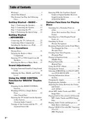
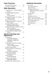
Step 1: Positioning the Speakers........... 10 Step 2: Connecting the System 13 Step 3: Connecting the TV 18 Step 4: Performing the Quick Setup ..... 19 Getting Started - Connecting the TV (Advanced 22 Connecting Other Components 25 Installing the Speakers on a Wall.......... 27 Basic Operations Playing ...Play) Enjoying the TV Sound from the Speakers in this System 44 (System Audio Control) Turning off the System with the TV ..... 45 (System Power Off) Enjoying STB (Set Top Box) Digital Sound or Digital Satellite Receiver Sound from the System 46 (STB SYNCHRO) Various Functions for...
Step 1: Positioning the Speakers........... 10 Step 2: Connecting the System 13 Step 3: Connecting the TV 18 Step 4: Performing the Quick Setup ..... 19 Getting Started - Connecting the TV (Advanced 22 Connecting Other Components 25 Installing the Speakers on a Wall.......... 27 Basic Operations Playing ...Play) Enjoying the TV Sound from the Speakers in this System 44 (System Audio Control) Turning off the System with the TV ..... 45 (System Power Off) Enjoying STB (Set Top Box) Digital Sound or Digital Satellite Receiver Sound from the System 46 (STB SYNCHRO) Various Functions for...
Operating Instructions
Page 5
... the Display or Sound Track Language 87 [LANGUAGE SETUP] Settings for the Display 88 [SCREEN SETUP] Custom Settings 91 [CUSTOM SETUP] Settings for the Speakers 92 [SPEAKER SETUP] Returning to the Default Settings.......... 95 Additional Information Precautions 96 Notes about the Discs 97 Troubleshooting 97 Self-diagnosis Function 101 (When letters/numbers... 102 Glossary 104 Language Code List 107 Index to Parts and Controls 108 Guide to the Control Menu Display ... 113 DVD Setup Display List 116 System Menu List 118 Tuner Menu List 118 Index 119 5US
... the Display or Sound Track Language 87 [LANGUAGE SETUP] Settings for the Display 88 [SCREEN SETUP] Custom Settings 91 [CUSTOM SETUP] Settings for the Speakers 92 [SPEAKER SETUP] Returning to the Default Settings.......... 95 Additional Information Precautions 96 Notes about the Discs 97 Troubleshooting 97 Self-diagnosis Function 101 (When letters/numbers... 102 Glossary 104 Language Code List 107 Index to Parts and Controls 108 Guide to the Control Menu Display ... 113 DVD Setup Display List 116 System Menu List 118 Tuner Menu List 118 Index 119 5US
Operating Instructions
Page 9
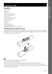
... use the remote, point it at the remote sensor on the batteries to direct sunlight or lighting apparatus. Getting Started - Unpacking • Control unit (1) • Speakers (5) • Subwoofer (1) • AM loop antenna (aerial) (1) • FM wire antenna (aerial) (1) • Video Cord (1) • Remote Commander (remote) (1) • R6 (size AA) batteries (2) •... place. • Do not use a new battery with an old one. • Do not drop any foreign object into the remote You can control the system using the supplied remote. Getting Started - BASIC -
... use the remote, point it at the remote sensor on the batteries to direct sunlight or lighting apparatus. Getting Started - Unpacking • Control unit (1) • Speakers (5) • Subwoofer (1) • AM loop antenna (aerial) (1) • FM wire antenna (aerial) (1) • Video Cord (1) • Remote Commander (remote) (1) • R6 (size AA) batteries (2) •... place. • Do not use a new battery with an old one. • Do not drop any foreign object into the remote You can control the system using the supplied remote. Getting Started - BASIC -

Operating Instructions
Page 10
... subwoofer as illustrated below. Close to a wall Note • If the subwoofer is placed outside (3). Step 1: Positioning the Speakers For the best possible surround sound, all the speakers other than 0.5 m (1.6 ft).* * 1 1 Surround speaker (L) Surround speaker (R) Tip • You can also place the subwoofer either side, facing the listening position. • When you install the...
... subwoofer as illustrated below. Close to a wall Note • If the subwoofer is placed outside (3). Step 1: Positioning the Speakers For the best possible surround sound, all the speakers other than 0.5 m (1.6 ft).* * 1 1 Surround speaker (L) Surround speaker (R) Tip • You can also place the subwoofer either side, facing the listening position. • When you install the...

Operating Instructions
Page 11
... solvent such as TV, etc. continued 11US Middle range sound will fall. Subject to direct sunlight • Use caution when placing the speakers and/or speaker stands (not supplied) that you change the settings. In this case, place the subwoofer away from the TV. For details, see "...Calibrating the Appropriate Settings Automatically" (page 83). Tip • When you change the positions of the speakers, it is installed. • Do not place the subwoofer back of the obstruction, such as alcohol or benzine. • Image distortion on ...
... solvent such as TV, etc. continued 11US Middle range sound will fall. Subject to direct sunlight • Use caution when placing the speakers and/or speaker stands (not supplied) that you change the settings. In this case, place the subwoofer away from the TV. For details, see "...Calibrating the Appropriate Settings Automatically" (page 83). Tip • When you change the positions of the speakers, it is installed. • Do not place the subwoofer back of the obstruction, such as alcohol or benzine. • Image distortion on ...

Operating Instructions
Page 12
Subwoofer Slits • Do not push the top of the subwoofer. Speaker unit 12US Getting Started - When lifting, hold the bottom of the subwoofer where the speaker unit is installed. BASIC - Note on handling the subwoofer • Do not place your hand into the slit of the subwoofer when lifting it. The speaker driver may be damaged.
Subwoofer Slits • Do not push the top of the subwoofer. Speaker unit 12US Getting Started - When lifting, hold the bottom of the subwoofer where the speaker unit is installed. BASIC - Note on handling the subwoofer • Do not place your hand into the slit of the subwoofer when lifting it. The speaker driver may be damaged.
Operating Instructions
Page 13
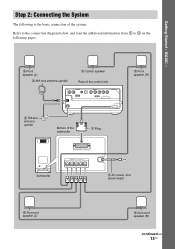
... of the control unit DMPORT 2 Front speaker (R) 3 FM wire antenna (aerial) Bottom of the system. Refer to the connection diagram below, and read the additional information from 1 to 4 on the following is the basic connection of the subwoofer 1 Plug Subwoofer SYSTEM CONTROL ONLY FOR HCD-IS10 SPEAKER ONLY FOR SS-IS10 FRONT R FRONT L SUR R SUR L CENTER...
... of the control unit DMPORT 2 Front speaker (R) 3 FM wire antenna (aerial) Bottom of the system. Refer to the connection diagram below, and read the additional information from 1 to 4 on the following is the basic connection of the subwoofer 1 Plug Subwoofer SYSTEM CONTROL ONLY FOR HCD-IS10 SPEAKER ONLY FOR SS-IS10 FRONT R FRONT L SUR R SUR L CENTER...
Operating Instructions
Page 14
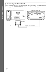
Insert the plug of the SYSTEM CONTROL cord, then secure the screws of the control unit Subwoofer SYSTEM CONTROL ONLY FOR HCD-IS10 SPEAKER ONLY FOR SS-IS10 FRONT R FRONT L SUR R SUR L CENTER Plug DMPORT Screws SYSTEM CONTROL cord 14US Bottom of the subwoofer Rear of the plug. BASIC - 1 Connecting the Control unit Connect the system connector of the control unit to the SYSTEM CONTROL jack of the subwoofer. Getting Started -
Insert the plug of the SYSTEM CONTROL cord, then secure the screws of the control unit Subwoofer SYSTEM CONTROL ONLY FOR HCD-IS10 SPEAKER ONLY FOR SS-IS10 FRONT R FRONT L SUR R SUR L CENTER Plug DMPORT Screws SYSTEM CONTROL cord 14US Bottom of the subwoofer Rear of the plug. BASIC - 1 Connecting the Control unit Connect the system connector of the control unit to the SYSTEM CONTROL jack of the subwoofer. Getting Started -
Operating Instructions
Page 15
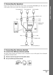
... AM loop antenna (aerial). The connectors of the speaker cords to receive AM signals. Front speaker (R) Front speaker (L) Center speaker Red Subwoofer SYSTEM CONTROL ONLY FOR HCD-IS10 SPEAKER ONLY FOR SS-IS10 FRONT R FRONT L SUR R SUR L CENTER Speaker cords Green White Bottom of the subwoofer Gray Blue Speaker cords Surround speaker (R) Surround speaker (L) 3 Connecting the Antenna (Aerial) To connect the AM...
... AM loop antenna (aerial). The connectors of the speaker cords to receive AM signals. Front speaker (R) Front speaker (L) Center speaker Red Subwoofer SYSTEM CONTROL ONLY FOR HCD-IS10 SPEAKER ONLY FOR SS-IS10 FRONT R FRONT L SUR R SUR L CENTER Speaker cords Green White Bottom of the subwoofer Gray Blue Speaker cords Surround speaker (R) Surround speaker (L) 3 Connecting the Antenna (Aerial) To connect the AM...

Operating Instructions
Page 17
BASIC - 4 Connecting the AC power cord (mains lead) Before connecting the AC power cord (mains lead) of the subwoofer to a wall outlet (mains), connect all the speakers to the subwoofer (page 15). Subwoofer To a wall outlet (mains) AC power cord (mains lead) Note • After connecting the AC power cord (mains lead), wait about 20 seconds before turning on the power by pressing "/1. 17US Getting Started -
BASIC - 4 Connecting the AC power cord (mains lead) Before connecting the AC power cord (mains lead) of the subwoofer to a wall outlet (mains), connect all the speakers to the subwoofer (page 15). Subwoofer To a wall outlet (mains) AC power cord (mains lead) Note • After connecting the AC power cord (mains lead), wait about 20 seconds before turning on the power by pressing "/1. 17US Getting Started -
Operating Instructions
Page 18
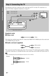
... page 25. : Video signal flow : Audio signal flow B AUDIO OUT L VIDEO IN R TV A DMPORT Rear of the control unit to the system. You can enjoy TV sound from the speakers with this connection. Step 3: Connecting the TV The following is the basic connection of the control unit to the TV. Connect the...
... page 25. : Video signal flow : Audio signal flow B AUDIO OUT L VIDEO IN R TV A DMPORT Rear of the control unit to the system. You can enjoy TV sound from the speakers with this connection. Step 3: Connecting the TV The following is the basic connection of the control unit to the TV. Connect the...

Operating Instructions
Page 20
.... Getting Started - Rear of the control unit DMPORT To ECM-AC2 jack Calibration mic 10 Press X/x to change the position of the speakers, reset the speaker settings. Measurement complete. BASIC - 9 Connect the calibration mic to select [YES]. Note • The ECM-AC2 jack is installed may...] starts. YES NO Note • The environment of each speaker should face the calibration mic, and there should be no obstruction between the speakers and the calibration mic. Be quiet during the measurement (which the system is used for the Speakers" (page 92). • If you want to select ...
.... Getting Started - Rear of the control unit DMPORT To ECM-AC2 jack Calibration mic 10 Press X/x to change the position of the speakers, reset the speaker settings. Measurement complete. BASIC - 9 Connect the calibration mic to select [YES]. Note • The ECM-AC2 jack is installed may...] starts. YES NO Note • The environment of each speaker should face the calibration mic, and there should be no obstruction between the speakers and the calibration mic. Be quiet during the measurement (which the system is used for the Speakers" (page 92). • If you want to select ...
Operating Instructions
Page 25
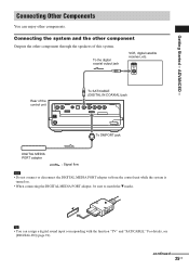
...DIGITAL IN] (page 91). To the digital coaxial output jack VCR, digital satellite receiver, etc. Connecting the system and the other component Outputs the other components. Tip • You can enjoy other component through the speakers of the control unit To SAT/CABLE (DIGITAL IN COAXIAL) jack DMPORT ...To DMPORT jack DIGITAL MEDIA PORT adapter : Signal flow Note • Do not connect or disconnect the DIGITAL MEDIA PORT adapter to/from the control unit while the system is turned on...
...DIGITAL IN] (page 91). To the digital coaxial output jack VCR, digital satellite receiver, etc. Connecting the system and the other component Outputs the other components. Tip • You can enjoy other component through the speakers of the control unit To SAT/CABLE (DIGITAL IN COAXIAL) jack DMPORT ...To DMPORT jack DIGITAL MEDIA PORT adapter : Signal flow Note • Do not connect or disconnect the DIGITAL MEDIA PORT adapter to/from the control unit while the system is turned on...

Operating Instructions
Page 27
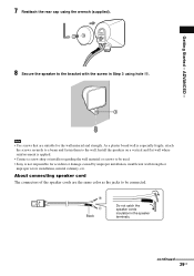
Installing the speakers on a wall. Wrench (supplied) Rear cap continued 27US Getting Started - ADVANCED - Installing the Speakers on a Wall You can use the speakers installed on a wall 1 Prepare screws (not supplied) that are suitable for the holes of the bracket. 2 Secure the bracket to the wall using hole 1. 1 2 34 Tip • To prevent the speaker from rotating, use the hole 2, too. 3 Remove the rear cap using the wrench (supplied), and remove the speaker pedestal using a screwdriver (+) (not supplied).
Installing the speakers on a wall. Wrench (supplied) Rear cap continued 27US Getting Started - ADVANCED - Installing the Speakers on a Wall You can use the speakers installed on a wall 1 Prepare screws (not supplied) that are suitable for the holes of the bracket. 2 Secure the bracket to the wall using hole 1. 1 2 34 Tip • To prevent the speaker from rotating, use the hole 2, too. 3 Remove the rear cap using the wrench (supplied), and remove the speaker pedestal using a screwdriver (+) (not supplied).

Operating Instructions
Page 28
speaker cords can be removed. 5 Thread the speaker cords through hole 3. 3 6 Reconnect the detached speaker cords, matching 3/# to the appropriate speaker terminals (1), and then push the lever down completely (2). (2) (1) 3 # Tip • If it is difficult to push the lever down , the When the lever is down , use the wrench (supplied). 28US 4 Push A with the supplied wrench (1), and then remove the speaker cords (2). (2) (1) A When the lever is up, the speaker cords are locked.
speaker cords can be removed. 5 Thread the speaker cords through hole 3. 3 6 Reconnect the detached speaker cords, matching 3/# to the appropriate speaker terminals (1), and then push the lever down completely (2). (2) (1) 3 # Tip • If it is difficult to push the lever down , the When the lever is down , use the wrench (supplied). 28US 4 Push A with the supplied wrench (1), and then remove the speaker cords (2). (2) (1) A When the lever is up, the speaker cords are locked.
Operating Instructions
Page 29
... are the same color as the jacks to be used. • Sony is applied. • Contact a screw shop or installer regarding the wall material or screws to the wall. ADVANCED - 8 Secure the speaker to the bracket with the screw in the speaker terminals. Getting Started - continued 29US As a plaster board wall is especially...
... are the same color as the jacks to be used. • Sony is applied. • Contact a screw shop or installer regarding the wall material or screws to the wall. ADVANCED - 8 Secure the speaker to the bracket with the screw in the speaker terminals. Getting Started - continued 29US As a plaster board wall is especially...
Operating Instructions
Page 30
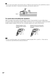
... sound will lack bass and may damage the system. If the cords are touching each speaker cord does not touch another speaker terminal. Stripped speaker cord is touching another speaker terminal or the bare wire of insulation. Note • Be sure to match the speaker cords to the appropriate speaker terminals: 3 to +, and # to follow these precautions...
... sound will lack bass and may damage the system. If the cords are touching each speaker cord does not touch another speaker terminal. Stripped speaker cord is touching another speaker terminal or the bare wire of insulation. Note • Be sure to match the speaker cords to the appropriate speaker terminals: 3 to +, and # to follow these precautions...
Operating Instructions
Page 36
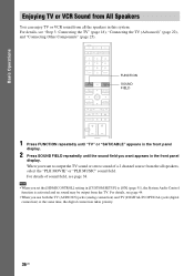
For details, see page 44. • When you want to [ON] (page 91), the System Audio Control function is activated and no sound may be output from the TV. For details, see "Step 3: Connecting the TV" (page 18), "Connecting the ... sound field, see page 38. For details of a 2 channel source from the all the speakers in the front panel display. Basic Operations Enjoying TV or VCR Sound from All Speakers You can enjoy TV or VCR sound from all speakers, select the "PLII MOVIE" or "PLII MUSIC" sound field. Note • When you...
For details, see page 44. • When you want to [ON] (page 91), the System Audio Control function is activated and no sound may be output from the TV. For details, see "Step 3: Connecting the TV" (page 18), "Connecting the ... sound field, see page 38. For details of a 2 channel source from the all the speakers in the front panel display. Basic Operations Enjoying TV or VCR Sound from All Speakers You can enjoy TV or VCR sound from all speakers, select the "PLII MOVIE" or "PLII MUSIC" sound field. Note • When you...
Operating Instructions
Page 38
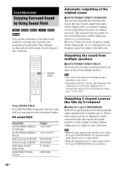
... a low frequency signal for output to the subwoofer. This mode presents the sound as the optimum mode is not output from multiple speakers. Press SOUND FIELD. reverberation). MULTI PLII MOVIE PLII MUSIC P. SOUND FIELD Automatic outputting of the original sound x AUTO FORMAT DIRECT... STANDARD The auto decoding function automatically detects the type of movie theaters into your home. STD." STD A.F.D. AUDIO OMNI-DIR Outputting 2 channel sources like CDs by selecting one of system's preprogrammed sound fields. This is input, Dolby Pro Logic II MOVIE/MUSIC are...
... a low frequency signal for output to the subwoofer. This mode presents the sound as the optimum mode is not output from multiple speakers. Press SOUND FIELD. reverberation). MULTI PLII MOVIE PLII MUSIC P. SOUND FIELD Automatic outputting of the original sound x AUTO FORMAT DIRECT... STANDARD The auto decoding function automatically detects the type of movie theaters into your home. STD." STD A.F.D. AUDIO OMNI-DIR Outputting 2 channel sources like CDs by selecting one of system's preprogrammed sound fields. This is input, Dolby Pro Logic II MOVIE/MUSIC are...


