Operating Instructions
Page 9
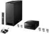
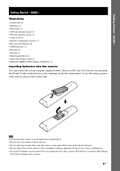
Getting Started - Getting Started - Unpacking • Control unit (1) • Speakers (5) • Subwoofer (1) • AM loop antenna (aerial) (1) • FM wire antenna (aerial) (1) • Video Cord (1) • Remote Commander (remote) (1) • R6 (size AA) batteries (2) • Calibration mic (1) • Brackets (5) •...use a new battery with an old one. • Do not drop any foreign object into the remote You can control the system using the supplied remote. To use the remote for an extended period of time, remove the batteries to the markings inside the ...
Getting Started - Getting Started - Unpacking • Control unit (1) • Speakers (5) • Subwoofer (1) • AM loop antenna (aerial) (1) • FM wire antenna (aerial) (1) • Video Cord (1) • Remote Commander (remote) (1) • R6 (size AA) batteries (2) • Calibration mic (1) • Brackets (5) •...use a new battery with an old one. • Do not drop any foreign object into the remote You can control the system using the supplied remote. To use the remote for an extended period of time, remove the batteries to the markings inside the ...

Operating Instructions
Page 10
... reinforce the bass sound, place the subwoofer possible close to a wall Note • If the subwoofer is placed outside (3). In this case, use a commercially available wire clamper or a commercially available tape, etc., to secure the speaker cord. • You may be placed (2). It is recommended that the subwoofer should be less...
... reinforce the bass sound, place the subwoofer possible close to a wall Note • If the subwoofer is placed outside (3). In this case, use a commercially available wire clamper or a commercially available tape, etc., to secure the speaker cord. • You may be placed (2). It is recommended that the subwoofer should be less...
Operating Instructions
Page 13
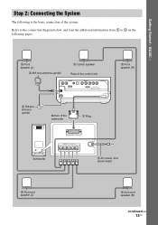
Step 2: Connecting the System The following pages. 2 Front speaker (L) 3 AM loop antenna (aerial) 2 Center speaker Rear of the control unit DMPORT 2 Front speaker (R) 3 FM wire antenna (aerial) Bottom of the system. Refer to the connection diagram below, and read the additional information... from 1 to 4 on the following is the basic connection of the subwoofer 1 Plug Subwoofer SYSTEM CONTROL ONLY FOR HCD-IS10 SPEAKER ONLY FOR SS-IS10 FRONT R FRONT ...
Step 2: Connecting the System The following pages. 2 Front speaker (L) 3 AM loop antenna (aerial) 2 Center speaker Rear of the control unit DMPORT 2 Front speaker (R) 3 FM wire antenna (aerial) Bottom of the system. Refer to the connection diagram below, and read the additional information... from 1 to 4 on the following is the basic connection of the subwoofer 1 Plug Subwoofer SYSTEM CONTROL ONLY FOR HCD-IS10 SPEAKER ONLY FOR SS-IS10 FRONT R FRONT ...

Operating Instructions
Page 16
.... The cords can be connected to the AM antenna (aerial) terminals. Insert the cords pushing down the terminal clamp. DMPORT Insert until this part. FM wire antenna (aerial) (supplied) DMPORT FM 75 Ω COAXIAL jack Note • Be sure to an outdoor FM antenna (aerial) as shown below. Tip &#... connecting the FM wire antenna (aerial), keep it as horizontal as noise may result. Getting Started - To connect the FM wire antenna (aerial) Connect the FM wire antenna (aerial) to the FM 75 Ω COAXIAL jack. Note • Do not place the AM loop antenna (aerial) near the system or other AV ...
.... The cords can be connected to the AM antenna (aerial) terminals. Insert the cords pushing down the terminal clamp. DMPORT Insert until this part. FM wire antenna (aerial) (supplied) DMPORT FM 75 Ω COAXIAL jack Note • Be sure to an outdoor FM antenna (aerial) as shown below. Tip &#... connecting the FM wire antenna (aerial), keep it as horizontal as noise may result. Getting Started - To connect the FM wire antenna (aerial) Connect the FM wire antenna (aerial) to the FM 75 Ω COAXIAL jack. Note • Do not place the AM loop antenna (aerial) near the system or other AV ...
Operating Instructions
Page 30
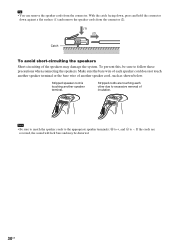
... cord is touching another speaker cord, such as shown below. Stripped cords are reversed, the sound will lack bass and may damage the system. Make sure the bare wire of each other due to -. Note • Be sure to match the speaker cords to the appropriate speaker terminals: 3 to +, and # to excessive... removal of another speaker terminal. If the cords are touching each speaker cord does not touch another speaker terminal or the bare wire of insulation. To prevent this, be distorted. 30US
... cord is touching another speaker cord, such as shown below. Stripped cords are reversed, the sound will lack bass and may damage the system. Make sure the bare wire of each other due to -. Note • Be sure to match the speaker cords to the appropriate speaker terminals: 3 to +, and # to excessive... removal of another speaker terminal. If the cords are touching each speaker cord does not touch another speaker terminal or the bare wire of insulation. To prevent this, be distorted. 30US
Operating Instructions
Page 103
...: Y: 1 Vp-p 75 ohms PB/CB, PR/CR: 0.7 Vp-p 75 ohms HDMI OUT: Type A (19 pin) Speakers Front/Center/Surround (SS-IS10) Speaker system Full range speaker system Speaker unit 35 mm (1 7/16 inches) Rated impedance 10 ohms Dimensions (approx.) 45 × 55 × 40 mm (1 13/16 × 2...to change without notice. • Standby power consumption 0.3 W (or less). • Halogenated flame retardants are not used in the printed wiring boards. • Over 85 % power efficiency of amplifier block is achieved with the full digital amplifier, S-master. • Halogenated flame retardants...
...: Y: 1 Vp-p 75 ohms PB/CB, PR/CR: 0.7 Vp-p 75 ohms HDMI OUT: Type A (19 pin) Speakers Front/Center/Surround (SS-IS10) Speaker system Full range speaker system Speaker unit 35 mm (1 7/16 inches) Rated impedance 10 ohms Dimensions (approx.) 45 × 55 × 40 mm (1 13/16 × 2...to change without notice. • Standby power consumption 0.3 W (or less). • Halogenated flame retardants are not used in the printed wiring boards. • Over 85 % power efficiency of amplifier block is achieved with the full digital amplifier, S-master. • Halogenated flame retardants...


