Operating Instructions
Page 16
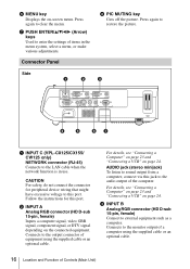
...NETWORK INPUT C RGB AUDIO INPUT A RGB AUDIO INPUT B MONITOR AUDIO S VIDEO VIDEO AUDIO OUTPUT VIDEO IN RS-232C REMOTE 4 5 67 a INPUT C (VPL-CX125/CX155/ CW125 only) NETWORK connector (RJ-45) Connects to enter the settings of the computer. For details, see "Connecting a Computer" on page 23 ... page 24. Follow the instructions for peripheral device wiring that might have excessive voltage to restore the picture. c INPUT B Analog RGB connector (HD D-sub 15-pin, female) Connect to clear the menu. g PUSH ENTER/v/V/b/B (Arrow) keys Used to the LAN cable when the network ...
...NETWORK INPUT C RGB AUDIO INPUT A RGB AUDIO INPUT B MONITOR AUDIO S VIDEO VIDEO AUDIO OUTPUT VIDEO IN RS-232C REMOTE 4 5 67 a INPUT C (VPL-CX125/CX155/ CW125 only) NETWORK connector (RJ-45) Connects to enter the settings of the computer. For details, see "Connecting a Computer" on page 23 ... page 24. Follow the instructions for peripheral device wiring that might have excessive voltage to restore the picture. c INPUT B Analog RGB connector (HD D-sub 15-pin, female) Connect to clear the menu. g PUSH ENTER/v/V/b/B (Arrow) keys Used to the LAN cable when the network ...
Operating Instructions
Page 17
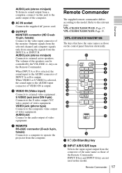
...video output of the same name as those of VIDEO IN is output. AUDIO - e OUTPUT MONITOR connector (HD D-sub 15-pin, female) Connect to operate the projector from the computer. Outputs signals from the selected channel and computer signals only from among the signals from the ...connector of video equipment. VPL-CX100/CX120/CX150: Page 19. g REMOTE RS-232C connector (D-sub 9-pin, female) Connects to a computer...
...video output of the same name as those of VIDEO IN is output. AUDIO - e OUTPUT MONITOR connector (HD D-sub 15-pin, female) Connect to operate the projector from the computer. Outputs signals from the selected channel and computer signals only from among the signals from the ...connector of video equipment. VPL-CX100/CX120/CX150: Page 19. g REMOTE RS-232C connector (D-sub 9-pin, female) Connects to a computer...
Operating Instructions
Page 23
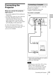
...Turn off all equipment before making any connections. • Use the proper cables for Network" stored on the CD-ROM. Connecting the Projector When you set the output mode of picture signals. For more information, refer to pull it out by the plug, not the ...) (Use a no-resistance cable.) B HD D-sub 15-pin cable Notes • The projector accepts VGA, SVGA, XGA, WXGA, SXGA and SXGA+ signals. loose connections may increase noise and reduce performance of your computer to XGA (VPL-CX100/CX120/CX125/CX150/ Connecting the Projector 23 Connecting a Computer This section describes how...
...Turn off all equipment before making any connections. • Use the proper cables for Network" stored on the CD-ROM. Connecting the Projector When you set the output mode of picture signals. For more information, refer to pull it out by the plug, not the ...) (Use a no-resistance cable.) B HD D-sub 15-pin cable Notes • The projector accepts VGA, SVGA, XGA, WXGA, SXGA and SXGA+ signals. loose connections may increase noise and reduce performance of your computer to XGA (VPL-CX100/CX120/CX125/CX150/ Connecting the Projector 23 Connecting a Computer This section describes how...

Operating Instructions
Page 25
... (not supplied) (Use a no-resistance cable.) B Signal Cable (not supplied) HD D-sub 15-pin (male) ↔ 3 × phono jack Notes • Set the aspect ratio using "Aspect" on the Setup menu. Connecting the Projector 25 setting on the Signal menu according to the input signal. • When you... connect the projector to a video GBR output connector, select "Video GBR" or when you connect the...
... (not supplied) (Use a no-resistance cable.) B Signal Cable (not supplied) HD D-sub 15-pin (male) ↔ 3 × phono jack Notes • Set the aspect ratio using "Aspect" on the Setup menu. Connecting the Projector 25 setting on the Signal menu according to the input signal. • When you... connect the projector to a video GBR output connector, select "Video GBR" or when you connect the...

Operating Instructions
Page 55
... terminated) G with sync/Y: 1 Vp-p ±2 dB sync negative (75 ohms terminated) B/B-Y: 0.7 Vp-p ±2 dB (75 ohms terminated) HD:Horizontal sync input: TTL level, high impedance, positive/ negative VD:Vertical sync input: TTL level, high impedance, positive/ negative AUDIO: Stereo minijack rated... 50/60 Hz Power consumption VPL-CX100/CX120/CX125/ CX150/CX155: Max. 285 W in standby (standard): 7 W in standby (low): 0.5 W VPL-CW125: Max. 287 W in standby (standard): 7 W in standby (low): 0.5 W Heat dissipation VPL-CX100/CX120/CX125/ CX150/CX155: 973 BTU VPL-CW125: 979 BTU Operating temperature ...
... terminated) G with sync/Y: 1 Vp-p ±2 dB sync negative (75 ohms terminated) B/B-Y: 0.7 Vp-p ±2 dB (75 ohms terminated) HD:Horizontal sync input: TTL level, high impedance, positive/ negative VD:Vertical sync input: TTL level, high impedance, positive/ negative AUDIO: Stereo minijack rated... 50/60 Hz Power consumption VPL-CX100/CX120/CX125/ CX150/CX155: Max. 285 W in standby (standard): 7 W in standby (low): 0.5 W VPL-CW125: Max. 287 W in standby (standard): 7 W in standby (low): 0.5 W Heat dissipation VPL-CX100/CX120/CX125/ CX150/CX155: 973 BTU VPL-CW125: 979 BTU Operating temperature ...
Operating Instructions
Page 56
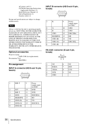
Optional accessories Projector Lamp LMP-C200 (for replacement) Presentation Tool RM-PJPK1 Pin assignment INPUT A connector (HD D-sub 15-pin, female) INPUT B connector (HD D-sub 15-pin, female) 1 R 9 Power supply input for DDC 2 G 10 GND 3 B 11 GND 4 GND 12 DDC/SDA 5 RESERVE 13 HD 6 GND ...Power supply input for DDC 2 G/Y 10 GND 3 B/B-Y 11 GND 4 GND 12 DDC/SDA 5 RESERVE 13 HD 6 GND (R) 14 VD 7 GND (G) 15 DDC/SCL 8 GND (B) 56 Specifications SONY WILL NOT BE LIABLE FOR DAMAGES OF ANY KIND INCLUDING, BUT NOT LIMITED TO, COMPENSATION OR REIMBURSEMENT ON ACCOUNT ...
Optional accessories Projector Lamp LMP-C200 (for replacement) Presentation Tool RM-PJPK1 Pin assignment INPUT A connector (HD D-sub 15-pin, female) INPUT B connector (HD D-sub 15-pin, female) 1 R 9 Power supply input for DDC 2 G 10 GND 3 B 11 GND 4 GND 12 DDC/SDA 5 RESERVE 13 HD 6 GND ...Power supply input for DDC 2 G/Y 10 GND 3 B/B-Y 11 GND 4 GND 12 DDC/SDA 5 RESERVE 13 HD 6 GND (R) 14 VD 7 GND (G) 15 DDC/SCL 8 GND (B) 56 Specifications SONY WILL NOT BE LIABLE FOR DAMAGES OF ANY KIND INCLUDING, BUT NOT LIMITED TO, COMPENSATION OR REIMBURSEMENT ON ACCOUNT ...

