Service Manual
Page 1
... REPLACING DVD DECK A1-5 • DISC REMOVAL METHOD AT NO POWER SUPPLY A1-6 • PARENTAL CONTROL-RATING A1-6 • ABOUT LEAD FREE SOLDER (PbF A1-7 • GENERAL SPECIFICATIONS A2-1~A2-7 • DISASSEMBLY INSTRUCTIONS B1-1~B3-2 • SERVICE MODE LIST ...C-1 • SERVICING FIXTURES AND TOOLS C-2 • RE-WRITE FOR DVD FIRMWARE C-2 • WHEN REPLACING EEPROM (MEMORY) IC C-3 • ELECTRICAL ADJUSTMENTS D-1~D-6 • TROUBLESHOOTING GUIDE E-1~E-9 • BLOCK DIAGRAM ...F-1~F-8 • PRINTED CIRCUIT BOARDS G-1~G-10 • SCHEMATIC DIAGRAMS...
... REPLACING DVD DECK A1-5 • DISC REMOVAL METHOD AT NO POWER SUPPLY A1-6 • PARENTAL CONTROL-RATING A1-6 • ABOUT LEAD FREE SOLDER (PbF A1-7 • GENERAL SPECIFICATIONS A2-1~A2-7 • DISASSEMBLY INSTRUCTIONS B1-1~B3-2 • SERVICE MODE LIST ...C-1 • SERVICING FIXTURES AND TOOLS C-2 • RE-WRITE FOR DVD FIRMWARE C-2 • WHEN REPLACING EEPROM (MEMORY) IC C-3 • ELECTRICAL ADJUSTMENTS D-1~D-6 • TROUBLESHOOTING GUIDE E-1~E-9 • BLOCK DIAGRAM ...F-1~F-8 • PRINTED CIRCUIT BOARDS G-1~G-10 • SCHEMATIC DIAGRAMS...

Service Manual
Page 3
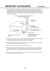
... type plug has two blades and a third grounding prong. When installing an outside antenna system should be taken to keep from tip-over. 13) Unplug this can fall into your safety. When a cart is used, use this apparatus near any type of fire or electric shock. 18) Do not push objects through any way, such as power-supply cord or plug...
... type plug has two blades and a third grounding prong. When installing an outside antenna system should be taken to keep from tip-over. 13) Unplug this can fall into your safety. When a cart is used, use this apparatus near any type of fire or electric shock. 18) Do not push objects through any way, such as power-supply cord or plug...
Service Manual
Page 4
...) If an outside antenna or cable system is connected to the unit, be sure the service technician uses replacement parts specified by the manufacturer or those that the unit is closing. Otherwise, sudden high volume sound may cause an electric shock and serious personal injury. Read the owner's manual of antenna discharge unit, connection to the minimum level before you connect the product to other...
...) If an outside antenna or cable system is connected to the unit, be sure the service technician uses replacement parts specified by the manufacturer or those that the unit is closing. Otherwise, sudden high volume sound may cause an electric shock and serious personal injury. Read the owner's manual of antenna discharge unit, connection to the minimum level before you connect the product to other...
Service Manual
Page 5
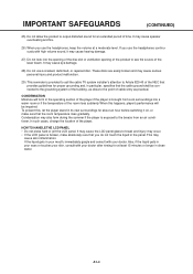
.... 29) This reminder is provided to call the cable TV system installer's attention to Article 820-40 of the NEC that provides guidelines for about an hour before switching it may occur. • If the LCD panel is broken, make absolutely sure that you use the headphones continuously with high volume sound, it on, or make sure that the...
.... 29) This reminder is provided to call the cable TV system installer's attention to Article 820-40 of the NEC that provides guidelines for about an hour before switching it may occur. • If the LCD panel is broken, make absolutely sure that you use the headphones continuously with high volume sound, it on, or make sure that the...
Service Manual
Page 6
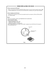
... operation, please read "PREPARATION OF SERVICING". • Use the Lead Free solder. • Manual soldering conditions • Soldering temperature: 320 ± 20oC • Soldering time: Within 3 seconds • Soldering combination: Sn-3.0Ag-0.5Cu • When Soldering/Removing of Pick Up PCB and DVD MT PCB connector. Fig. 1 A1-5 WHEN REPLACING DVD DECK [ When removing the DVD Deck ] Before removing Pick Up PCB and DVD...
... operation, please read "PREPARATION OF SERVICING". • Use the Lead Free solder. • Manual soldering conditions • Soldering temperature: 320 ± 20oC • Soldering time: Within 3 seconds • Soldering combination: Sn-3.0Ag-0.5Cu • When Soldering/Removing of Pick Up PCB and DVD MT PCB connector. Fig. 1 A1-5 WHEN REPLACING DVD DECK [ When removing the DVD Deck ] Before removing Pick Up PCB and DVD...
Service Manual
Page 7
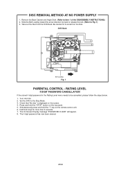
... menu needs to Fig. 1) 3. A1-6 DVD Deck Belt Loading Fig. 1 PARENTAL CONTROL - The On Screen Display message "PASSWORD CLEAR" will appear. 8. Take out the Disc from the DVD Deck. Hold both keys for more than 2 seconds. 7. Set the DVD to item 1 of the DISASSEMBLY INSTRUCTIONS.) 2. Press and hold the "7" key on the top panel. 5. Simultaneously press and hold the "STOP" button on the remote control unit. 6. Turn...
... menu needs to Fig. 1) 3. A1-6 DVD Deck Belt Loading Fig. 1 PARENTAL CONTROL - The On Screen Display message "PASSWORD CLEAR" will appear. 8. Take out the Disc from the DVD Deck. Hold both keys for more than 2 seconds. 7. Set the DVD to item 1 of the DISASSEMBLY INSTRUCTIONS.) 2. Press and hold the "7" key on the top panel. 5. Simultaneously press and hold the "STOP" button on the remote control unit. 6. Turn...
Service Manual
Page 9
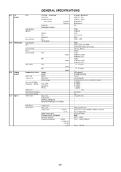
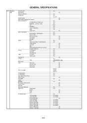
... System Tuner and Receive CH Intermediate Digital Frequency Analog Preset CH Stereo/Dual TV Sound Tuner Sound Muting Video Signal Fwd Rev Analog Digital System Destination CH Coverage Picture(FP) Sound(FS) FP-FS Input Level Output Level S/N Ratio (Weighted) Horizontal Resolution at DVD Mode Actual Actual RGB Signal Audio Signal Output Level Input Level Output Level at DVD at TV Digital Output Level S/N Ratio at DVD (Weighted) Harmonic Distortion Frequency Response : at DVD at Video CD at SVCD at CD 31.5 inch / 800.4mmV Color TFT LCD...
... System Tuner and Receive CH Intermediate Digital Frequency Analog Preset CH Stereo/Dual TV Sound Tuner Sound Muting Video Signal Fwd Rev Analog Digital System Destination CH Coverage Picture(FP) Sound(FS) FP-FS Input Level Output Level S/N Ratio (Weighted) Horizontal Resolution at DVD Mode Actual Actual RGB Signal Audio Signal Output Level Input Level Output Level at DVD at TV Digital Output Level S/N Ratio at DVD (Weighted) Harmonic Distortion Frequency Response : at DVD at Video CD at SVCD at CD 31.5 inch / 800.4mmV Color TFT LCD...
Service Manual
Page 11
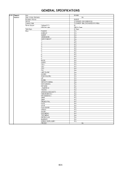
... Remote Control GENERAL SPECIFICATIONS Unit Glow in Dark Remocon Remocon Format Format Custom Code Power Source Total Keys Keys Voltage(D.C) UM size x pcs POWER DISPLAY SLEEP VIEW MODE INPUT SELECT 1 2 3 4 5 6 7 8 9 0 MUTE AUDIO VOL+ VOLCH+ CHLEFT/SLOWENTER RIGHT/SLOW+ UP DOWN SETUP/TV MENU EXIT/CANCEL RETURN ./SUBTITLE TV/DVD OPEN/CLOSE(EJECT) FWD(SEARCH+) REV(SEARCH-) SKIP+ SKIPPAUSE/STILL PLAY STOP PLAY MODE ANGLE ZOOM DVD MENU TOP MENU REPEAT A-B MARKER DIRECT SKIP(JUMP) FREEZE RC-MR No SHARP TV:SHARP, DVD...
... Remote Control GENERAL SPECIFICATIONS Unit Glow in Dark Remocon Remocon Format Format Custom Code Power Source Total Keys Keys Voltage(D.C) UM size x pcs POWER DISPLAY SLEEP VIEW MODE INPUT SELECT 1 2 3 4 5 6 7 8 9 0 MUTE AUDIO VOL+ VOLCH+ CHLEFT/SLOWENTER RIGHT/SLOW+ UP DOWN SETUP/TV MENU EXIT/CANCEL RETURN ./SUBTITLE TV/DVD OPEN/CLOSE(EJECT) FWD(SEARCH+) REV(SEARCH-) SKIP+ SKIPPAUSE/STILL PLAY STOP PLAY MODE ANGLE ZOOM DVD MENU TOP MENU REPEAT A-B MARKER DIRECT SKIP(JUMP) FREEZE RC-MR No SHARP TV:SHARP, DVD...
Service Manual
Page 12
... Red, Green, Blue Auto Adjust Backlight Audio MTS Tone Control (Bass/Treble/Balance) Stable Sound Surround BBE SRS WOW (SRS 3D/Focus/Tru Bass) Variable Audio Out Tuning CH Program Air/Cable ADD/DELETE Label CH Label Video Label Favorite CH V-Chip Type RRT Setup Lock Hotel Lock Channel Lock Video Lock Panel Lock Menu Language Closed Caption CC Advanced View Mode (Picture Size) Picture Scroll Film Mode Aspect Backlight PFC(Power Factor circuit) Freeze frame PIP/POP Direct Input Selection Digital Out Dolby Digital...
... Red, Green, Blue Auto Adjust Backlight Audio MTS Tone Control (Bass/Treble/Balance) Stable Sound Surround BBE SRS WOW (SRS 3D/Focus/Tru Bass) Variable Audio Out Tuning CH Program Air/Cable ADD/DELETE Label CH Label Video Label Favorite CH V-Chip Type RRT Setup Lock Hotel Lock Channel Lock Video Lock Panel Lock Menu Language Closed Caption CC Advanced View Mode (Picture Size) Picture Scroll Film Mode Aspect Backlight PFC(Power Factor circuit) Freeze frame PIP/POP Direct Input Selection Digital Out Dolby Digital...
Service Manual
Page 14
... Diagram Antenna Change Plug Service Facility List Important Safeguard Dew/AHC Caution Sheet Quick Set-up Sheet Battery UM size x pcs OEM Brand AC Adapter AC Cord (for AC Adapter) AC Cord (Flat Polarity Plugs) Cable Cramp Stand Stand Screw Hexagon Wrench AV Cord (2Pin-1Pin) Registration Card (NDL Card) 300 to 75ohm Antenna Adapter Sheet Information (Return) Sheet Information (HDMI) Sheet Information (CEA) Sheet Information(FCC) Cleaning Cloth Switch Top Power (Tact) Channel Up Channel Down Volume...
... Diagram Antenna Change Plug Service Facility List Important Safeguard Dew/AHC Caution Sheet Quick Set-up Sheet Battery UM size x pcs OEM Brand AC Adapter AC Cord (for AC Adapter) AC Cord (Flat Polarity Plugs) Cable Cramp Stand Stand Screw Hexagon Wrench AV Cord (2Pin-1Pin) Registration Card (NDL Card) 300 to 75ohm Antenna Adapter Sheet Information (Return) Sheet Information (HDMI) Sheet Information (CEA) Sheet Information(FCC) Cleaning Cloth Switch Top Power (Tact) Channel Up Channel Down Volume...

Service Manual
Page 15
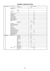
...Sets --- / --- --- --- Input 2 Video Output Audio Output Component Input 1 Analog Audio Component Input 2 Analog Audio HDMI Input 1 Analog Audio HDMI Input 2 Analog Audio Sub Woofer Out PC Monitor Input Analog Audio Digital Audio Output DC Jack (Center +) VHF/UHF Antenna Input Video Input 3 Audio Input 3 S - Double/Brown No No 900 x 286 x 659 Yes 1 Corner / 3 Edges / 5 Surfaces 32 321 Sets/40' container No No PC+ABS 94V0 NON-HALOGEN PS 94V0 NON-DECABROM -- Input 3 Other Terminal AC Inlet Approx. GENERAL SPECIFICATIONS G-14 Set Size G-15 Weight...
...Sets --- / --- --- --- Input 2 Video Output Audio Output Component Input 1 Analog Audio Component Input 2 Analog Audio HDMI Input 1 Analog Audio HDMI Input 2 Analog Audio Sub Woofer Out PC Monitor Input Analog Audio Digital Audio Output DC Jack (Center +) VHF/UHF Antenna Input Video Input 3 Audio Input 3 S - Double/Brown No No 900 x 286 x 659 Yes 1 Corner / 3 Edges / 5 Surfaces 32 321 Sets/40' container No No PC+ABS 94V0 NON-HALOGEN PS 94V0 NON-DECABROM -- Input 3 Other Terminal AC Inlet Approx. GENERAL SPECIFICATIONS G-14 Set Size G-15 Weight...
Service Manual
Page 16
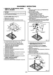
REMOVAL OF MECHANICAL PARTS AND P.C. Remove the 13 screws (1). 2. Manual soldering conditions • Soldering temperature: 320 ± 20oC • Soldering time: Within 3 seconds • Soldering combination: Sn-3.0Ag-0.5Cu 4. Remove the screw (3). 7. Remove the DVD MT PCB in the direction of arrow (A). 3. Remove the Plate Button Ass'y in the direction of arrow (B). 8. Remove the 2 screws (2). 6. Use the Lead Free solder. 3. Short circuit the position shown in the...
REMOVAL OF MECHANICAL PARTS AND P.C. Remove the 13 screws (1). 2. Manual soldering conditions • Soldering temperature: 320 ± 20oC • Soldering time: Within 3 seconds • Soldering combination: Sn-3.0Ag-0.5Cu 4. Remove the screw (3). 7. Remove the DVD MT PCB in the direction of arrow (A). 3. Remove the Plate Button Ass'y in the direction of arrow (B). 8. Remove the 2 screws (2). 6. Use the Lead Free solder. 3. Short circuit the position shown in the...
Service Manual
Page 19
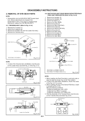
.... 3. Remove the Insulator (F). 2. Remove the 3 screws (1). 2. Remove the Rack Feed Ass'y. 7. Remove the Switch PCB Ass'y. 9. Then install it correctly as shown Fig. 2-2-B. REMOVAL OF DVD DECK PARTS NOTE 1. Minute adjustments are needed if the disassembly is needed except listed parts, replace the DVD MECHA ASS'Y. 2-1: TRAVERSE ASS'Y (Refer to Fig. 2-2-A) 1. In case of the Gear Motor installation, check if the value of the Switch PCB Ass'y, install it . 2. Manual soldering...
.... 3. Remove the Insulator (F). 2. Remove the 3 screws (1). 2. Remove the Rack Feed Ass'y. 7. Remove the Switch PCB Ass'y. 9. Then install it correctly as shown Fig. 2-2-B. REMOVAL OF DVD DECK PARTS NOTE 1. Minute adjustments are needed if the disassembly is needed except listed parts, replace the DVD MECHA ASS'Y. 2-1: TRAVERSE ASS'Y (Refer to Fig. 2-2-A) 1. In case of the Gear Motor installation, check if the value of the Switch PCB Ass'y, install it . 2. Manual soldering...
Service Manual
Page 23
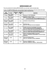
... PASSWORD. 2 sec. C-1 Releasing of PARENTAL LOCK. Refer to the "ELECTRICAL ADJUSTMENT" (On-Screen Display Adjustment). DOWN (Minimum) Remocon Key 0 TV mode VOL. NOTE: If you can repair, examine and adjust easily. DOWN (Minimum) 9 DVD mode STOP 1 (No disc) 2 sec. Refer to the "PARENTAL CONTROL - DVD Write mode. DOWN (Minimum) 1 Standard Time Operations 2 sec. DVD mode (No disc) STOP 7 2 sec. Refer to the "WHEN REPLACING EEPROM (MEMORY) IC". Initialization of the Adjustment MENU on the remote control...
... PASSWORD. 2 sec. C-1 Releasing of PARENTAL LOCK. Refer to the "ELECTRICAL ADJUSTMENT" (On-Screen Display Adjustment). DOWN (Minimum) Remocon Key 0 TV mode VOL. NOTE: If you can repair, examine and adjust easily. DOWN (Minimum) 9 DVD mode STOP 1 (No disc) 2 sec. Refer to the "PARENTAL CONTROL - DVD Write mode. DOWN (Minimum) 1 Standard Time Operations 2 sec. DVD mode (No disc) STOP 7 2 sec. Refer to the "WHEN REPLACING EEPROM (MEMORY) IC". Initialization of the Adjustment MENU on the remote control...
Service Manual
Page 24
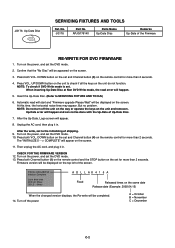
... FIRMWARE VERSION 12. Firmware version will happen and can not be displayed on the screen. 3. Turn off the unit on the way or operate the keys on the set the DVD mode. 2. Press both Channel button (1) on the remote control and the STOP button on the unit and remocon. DOWN button on the set and Channel button (5) on the power, and set the DVD mode. 10. UP/DOWN button on the power, and set the DVD mode...
... FIRMWARE VERSION 12. Firmware version will happen and can not be displayed on the screen. 3. Turn off the unit on the way or operate the keys on the set the DVD mode. 2. Press both Channel button (1) on the remote control and the STOP button on the unit and remocon. DOWN button on the set and Channel button (5) on the power, and set the DVD mode. 10. UP/DOWN button on the power, and set the DVD mode...
Service Manual
Page 25
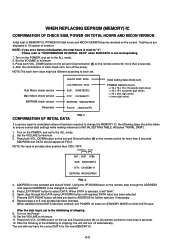
... to STANDBY MODE) to the initializing of shipping. 9. After the data input, set and Channel button (1) on the remote control for the new MEMORY IC. DOWN button on the set to finish DATA input. C-3 DOWN button on the set a factory initialization, the total hours is undertaken where it will now have the correct DATA for more than 2 seconds. Using the UP/DOWN buton on the screen...
... to STANDBY MODE) to the initializing of shipping. 9. After the data input, set and Channel button (1) on the remote control for the new MEMORY IC. DOWN button on the set to finish DATA input. C-3 DOWN button on the set a factory initialization, the total hours is undertaken where it will now have the correct DATA for more than 2 seconds. Using the UP/DOWN buton on the screen...
Service Manual
Page 26
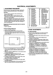
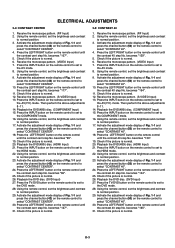
... BAK LIGHT CENT 30 BAK LIGHT MAX NO. Receive the gray scale pattern from the Pattern Generator. 3. Press the VOL. To display the adjustment screen for electrical adjustments. 1. Perform the above adjustments 6 and 7 until the white color is achieved. Prepare the following measurement tools for TV, AV, COMPONENT, HDMI and PC mode, press the INPUT button on the remote control to the AV mode. 4. NO. Press the INPUT button on the remote control to set in...
... BAK LIGHT CENT 30 BAK LIGHT MAX NO. Receive the gray scale pattern from the Pattern Generator. 3. Press the VOL. To display the adjustment screen for electrical adjustments. 1. Perform the above adjustments 6 and 7 until the white color is achieved. Prepare the following measurement tools for TV, AV, COMPONENT, HDMI and PC mode, press the INPUT button on the remote control to the AV mode. 4. NO. Press the INPUT button on the remote control to set in...
Service Manual
Page 27
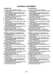
... HDMI mode. 22. Press the LEFT/RIGHT button on the remote control until the brightness cent step No. Receive the monoscope pattern. (RF Input) 2. Activate the adjustment mode display of Fig. 1-1 and press the channel button (43) on the remote control to set the brightness and contrast to the DVD mode. 28. Check if the picture is normal. 12. Press the INPUT button on the remote control to set to normal position. 9. Receive the monoscope pattern. (S-VIDEO Input...
... HDMI mode. 22. Press the LEFT/RIGHT button on the remote control until the brightness cent step No. Receive the monoscope pattern. (RF Input) 2. Activate the adjustment mode display of Fig. 1-1 and press the channel button (43) on the remote control to set the brightness and contrast to the DVD mode. 28. Check if the picture is normal. 12. Press the INPUT button on the remote control to set to normal position. 9. Receive the monoscope pattern. (S-VIDEO Input...
Service Manual
Page 28
.../RIGHT button on the remote control to set to the HDMI mode. 22. becomes "96". 25. Playback the DVD disc. (DVD Input) 27. Activate the adjustment mode display of Fig. 1-1 and press the channel button (42) on the remote control to set to the COMPONENT mode. 16. Check if the picture is normal. Receive the monoscope pattern. (S-VIDEO Input) 13. Press the INPUT button on the remote control to select "CONTRAST CENTER". 30. Press the INPUT button on the remote control until...
.../RIGHT button on the remote control to set to the HDMI mode. 22. becomes "96". 25. Playback the DVD disc. (DVD Input) 27. Activate the adjustment mode display of Fig. 1-1 and press the channel button (42) on the remote control to set to the COMPONENT mode. 16. Check if the picture is normal. Receive the monoscope pattern. (S-VIDEO Input) 13. Press the INPUT button on the remote control to select "CONTRAST CENTER". 30. Press the INPUT button on the remote control until...

Service Manual
Page 29
...according to the situation of the adjustment item is set . D-4 D-5 ELECTRICAL ADJUSTMENTS 2-6: Confirmation of Fixed Value (Step No.) Please check if the fixed values of each of the set correctly referring below. (TV/AV/COMPONENT/HDMI/DVD/PC/DTV) NO. with x mark, no use. FUNCTION TV Step No. 1 H POSI...31 BAK LIGHT MIN 0 32 BRIGHT CENT 115 33 BRIGHT MAX 200 34 BRIGHT MIN 60 35 TINT 122 36 SHARP H1 MAX 511 37 SHARP H1 MIN 0 38 SHARP H2 MAX 511 39 SHARP H2 MIN 0 40 SHARP V1 MAX 511 41 SHARP V1 MIN 0 42 CONT CENTER * 43 CONT MAX * 44 CONT MIN 60 45 COLOR...
...according to the situation of the adjustment item is set . D-4 D-5 ELECTRICAL ADJUSTMENTS 2-6: Confirmation of Fixed Value (Step No.) Please check if the fixed values of each of the set correctly referring below. (TV/AV/COMPONENT/HDMI/DVD/PC/DTV) NO. with x mark, no use. FUNCTION TV Step No. 1 H POSI...31 BAK LIGHT MIN 0 32 BRIGHT CENT 115 33 BRIGHT MAX 200 34 BRIGHT MIN 60 35 TINT 122 36 SHARP H1 MAX 511 37 SHARP H1 MIN 0 38 SHARP H2 MAX 511 39 SHARP H2 MIN 0 40 SHARP V1 MAX 511 41 SHARP V1 MIN 0 42 CONT CENTER * 43 CONT MAX * 44 CONT MIN 60 45 COLOR...


