Sharp LC32DV24U Support Question
Sharp LC32DV24U Support Question
Find answers below for this question about Sharp LC32DV24U - 31.5" LCD TV.Need a Sharp LC32DV24U manual? We have 1 online manual for this item!
Question posted by asun66 on November 11th, 2010
T V Set Up
I lost my manual , my TV got all reset by my daughters friends now I cant get the channels back the way they were. I have tried everything, i currently do not have cable but would get a few basic channels, im trying everything with the ch set up but i think the situation is getting worse maybe i can acsess a manual online? Thanks April
Current Answers
Related Sharp LC32DV24U Manual Pages
Service Manual - Page 1
... MANUAL
S68ONLC32DV24
COMBINATION LIQUID CRYSTAL TELEVISION AND DVD/CD PLAYER
MODEL LC-32DV24U
In the interests of the set.
The contents are important for maintaining the safety of the set ... safety and performance of user-safety (Required by safety regulations in some countries) the set . SHARP CORPORATION
This document has been published to change without notice. CONTENTS
Page
&#...
Service Manual - Page 5
... with your doctor after rinsing for at a moderate level. It may occur. • If the LCD panel is brought from an air conditioner. In such cases, change the location of time. This may cause...and product malfunction.
29) This reminder is provided to call the cable TV system installer's attention to Article 820-40 of cable entry as close to the point of the NEC that provides guidelines...
Service Manual - Page 7
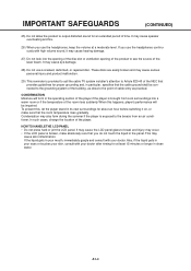
... REMOVAL METHOD AT NO POWER SUPPLY
1. Remove the Back Cabinet and Angle Deck. (Refer to the Stop Mode. 3. DVD Deck
Belt Loading
Fig. 1
PARENTAL CONTROL - Set the DVD to item 1 of the DISASSEMBLY INSTRUCTIONS.) 2. Check that "No disc" is displayed on the top...
Service Manual - Page 9
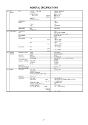
GENERAL SPECIFICATIONS
G-1 TV System
LCD
Color System Speaker
Sound Output
G-2 DVD System
Color System Disc
LCD Size / Visual Size LCD Type Number of Pixels
View Range
Bright Dot Zero ...Actual
RGB Signal Audio Signal
Output Level
Input Level
Output Level
at DVD
at TV
Digital Output Level
S/N Ratio at DVD (Weighted)
Harmonic Distortion
Frequency Response :
at DVD
at Video CD
at...
Service Manual - Page 12
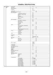
...
Auto Setup(Language/CH Program)
Picture Setting(TV)
AV Mode(Picture Preference)
Brightness , Contrast , Color
Tint
Sharpness
Color Temperature
DNR
Cable Clear
Picture Setting(PC)
HOR Position , VER Position
...
CH Program
Air/Cable
ADD/DELETE
Label
CH Label
Video Label
Favorite CH
V-Chip
Type
RRT Setup
Lock
Hotel Lock
Channel Lock
Video Lock
Panel Lock
Menu Language
...
Service Manual - Page 14
... Sheet
Circuit Diagram
Antenna Change Plug
Service Facility List
Important Safeguard
Dew/AHC Caution Sheet
Quick Set-up Sheet
Battery
UM size x pcs
OEM Brand
AC Adapter
AC Cord (for AC Adapter)
AC Cord (Flat Polarity Plugs)
Cable Cramp
Stand
Stand Screw
Hexagon Wrench
AV Cord (2Pin-1Pin)
Registration Card (NDL Card)
300...
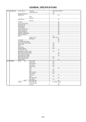
Service Manual - Page 15

.../ 3 Edges / 5 Surfaces
32
321
Sets/40' container
No
No
PC+ABS 94V0 NON-HALOGEN
PS 94V0 NON-DECABROM
-- GENERAL SPECIFICATIONS
G-14 Set Size G-15 Weight G-16 Carton
G-17 ...Height (cm)
Container Stuffing (40' container)
w/Pallet
w/Wrapping
Cabinet Front
Rear
Jack Panel
PCB
Non-Halogen Demand
Eyelet Demand
Environmental standard requirement
Pb-free
Measures for Whisker
Rohs...
Service Manual - Page 17
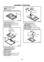
... the Plate Jack in the direction of arrow (A). 7.
Remove the Angle Main. Angle Main
(2)
(2) Angle Main
(1) (1) (1) LCD Block
(1) Holder Panel-2 Holder Panel-1
Fig. 1-6
1-7: POWER PCB (Refer to Fig. 1-4) 1. Fig. 1-7
B1-2 Remove the LCD Block in the
direction of arrow. 4. Remove the 6 screws (5). 8. DISASSEMBLY INSTRUCTIONS
1-4: REMOCON PCB (Refer to Fig. 1-7)
1. Remove...
Service Manual - Page 23
...
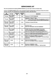
ALL mode
VOL. DOWN (Minimum)
8
ALL mode
VOL. POWER ON total hours are reset such
as the channel setting, and the POWER ON total hours.
Refer to the SERVICE MODE function, press and hold ... for more than a the standard time in the appropriate condition. (See below chart.)
Set Condition
TV mode
Set Key
VOL.
Releasing of MEMORY IC.
Can be checked of the INITIAL DATA of PARENTAL...
Service Manual - Page 24
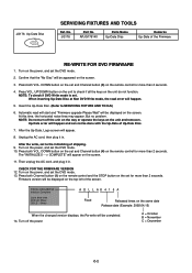
...lines may appear. Turn off the unit on the way or operate the keys on the screen. DOWN button on the set to the initializing of the screen. After the Up...Fixed
Released times on the remote control for more than 2 seconds. Press both Channel button (1) on the remote control and the STOP button on the set and Channel button (5) on the same date Release date (Example: 2008.04.15)
When...
Service Manual - Page 25
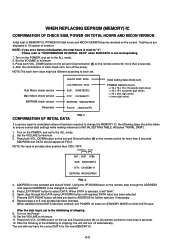
... Channel button (8) on the set a factory initialization, the total hours is undertaken where it will now have the correct DATA for more than 2 seconds. 12.
DOWN button on the remote control for more than 2 seconds. 4.
Sub Micon check version Main Micon check version
EEPROM check version Parameter
CHECK SUM: 3D05 LCD PWR ON...
Service Manual - Page 26
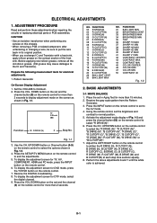
.... To display the adjustment screen for more than 15 minutes. 2. BASIC ADJUSTMENTS
2-1: WHITE BALANCE
1. Place the set to select the "R DRIVE (N)", "R CUTOFF (N)", "B DRIVE (N)",...the channel button (03) on the remote control to
the AV mode. 4. FUNCTION 31 BAK...TV/DVD button on the remote control.
6. Prepare the following measurement tools for DTV mode, select
the digital channel. 9. Set...
Service Manual - Page 27
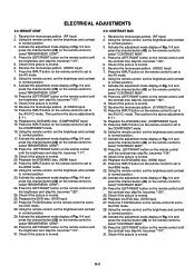
.... (DVD Input) 27. Press the TV/DVD button on the remote control until the contrast max step No. Activate the adjustment mode display of Fig. 1-1 and press the channel button (32) on the remote control to the DVD mode. 28. becomes "113". 31. Using the remote control, set the brightness and contrast to normal...
Service Manual - Page 28
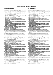
...Input) 21. Press the TV/DVD button on the remote control to set to the AV(Y/C) mode. D-3 becomes "107". 5. Activate the adjustment mode display of Fig. 1-1 and
press the channel button (50) on the...27. Press the LEFT/RIGHT button on the remote control to set the brightness and contrast to the AV mode. 8. becomes "165". 31. Press the LEFT/RIGHT button on the remote control to select...
Service Manual - Page 29

...
2-6: Confirmation of Fixed Value (Step No.) Please check if the fixed values of each of the set correctly referring below. (TV/AV/COMPONENT/HDMI/DVD/PC/DTV)
NO. D-4
D-5
FUNCTION
TV
Step No.
1 H POSI OSD
×
2 V POSI OSD
×
3 R.DRIVE (N)
...POSI 50
×
29 BAK LIGHT CENT
50
30 BAK LIGHT MAX
100
31 BAK LIGHT MIN
0
32 BRIGHT CENT
115
33 BRIGHT MAX
200
34 BRIGHT...
Service Manual - Page 34
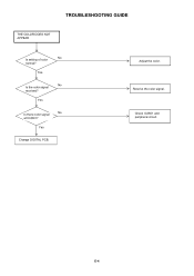
Adjust the color.
E-4
Receive the color signal.
Yes
Change DIGITAL PCB.
TROUBLESHOOTING GUIDE
THE COLOR DOES NOT APPEAR
Is setting of color
No
normal? Check IC2801 and peripheral circuit.
Yes
Is there color signal
No
at IC2801? Yes
Is the color signal
No
received?
Service Manual - Page 36
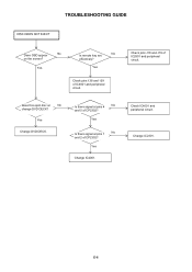
... OSD appear
No
on the screen? Yes
Check pins 138 and 139 of CP2302?
Check pins J18 and J19 of CP2302?
Yes
Is remote key set
No
effectively? Yes
Change DVD DECK. Check IC4001 and peripheral circuit.
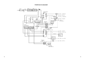
Service Manual - Page 41
...
32
SW
POWER SW
TRANSFORMER IC406
T401
PS2561AL1-1-V(W)
8
10
7
13
5
14
15
SOUND +B
2
1 IC407 DC/DC(5V) LA5779-E
FEED BACK
IC408
SW
PS2561AL1-1-V(W)
41 32
31
CP401__1.TUNER+30V CP401__7.8. LCD+B CP401__13. LCD_H
REGULATOR IC403 KIA431A-AT
F-3
F-4 POWER FAIL CP401__6.P.CON+5V CP401__3. AT+5V CP401__2.
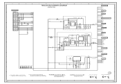
Service Manual - Page 64
... DES PIECES
CAUTION:SINCE THESE PARTS MARKED BY ARE CRITICAL FOR SAFETY,USE ONES DESCRIBED IN PARTS LIST ONLY
A
B
C
H-31
D
E
F
CAUTION: DIGITAL TRANSISTOR G
PCBDH0 CEG352
CAUTION: DIGITAL TRANSISTOR 1
H
H-32 A
B
C
D
E
F
...(typ 1.8A) D1.0V
BLM18PG181SN1D
D3.3V D5.0V
GND
7
FROM/TO SCALER VIDEO/AUDIO
LCD-H
AT+3.3V
VDIM D3.3V GND
TO TUNER
TUNER+30V
D3.3V
D5.0V
GND
6
TO...
Service Manual - Page 90
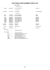
...CD2804
06CHRU2211 CORD CONNECTOR
CHRU2211
*** AC CORD ***
! SP301 ! V2301
09EV132026 LCD
V315B1-L06
RESISTOR RC
CARBON RESISTOR
CAPACITORS CC CE CP CPP CPL CMP ...METAL POLYESTER CAPACITOR METAL PLASTIC CAPACITOR METAL POLYPROPYLENE CAPACITOR
K3-8 CD3805
120V115909 CORD SET AC
QACCDA038WJPZ
*** OTHERS ***
BT001 BT002
141R003018 141R003018
BATTERY,MANGAN BATTERY,MANGAN
GR6M...
Similar Questions

Sharp Lcd Tv Lc50lb261u Firmware Upgrade? Where Do I Find The Binary File?
Where do I find the binary file for my Sharp LCD TV LC50LB261U firmware update. Need to download the...
Where do I find the binary file for my Sharp LCD TV LC50LB261U firmware update. Need to download the...
(Posted by mcraner234 6 years ago)

Factory Settings
I need to reset my tv back to factory settings or find out what the proper settings should be for th...
I need to reset my tv back to factory settings or find out what the proper settings should be for th...
(Posted by btywheeler 9 years ago)

I Am Not Getting Any Picture From The Lcd Tv When I Tried To Connect It To The C
I am not getting any picture from the LCD TV when I tried to connect it to the cable.
I am not getting any picture from the LCD TV when I tried to connect it to the cable.
(Posted by kadbry 12 years ago)

Lcd Tv -- Lamp
Does the sharp LC42SB45UT LCD TV contain a lamp?The Sharp warranty will not cover a tech to come out...
Does the sharp LC42SB45UT LCD TV contain a lamp?The Sharp warranty will not cover a tech to come out...
(Posted by kles 12 years ago)
Can You Set This Tv To Auto Turn On?
(Posted by snichols25 13 years ago)