
Operating Instructions
Page 11
... 72 Black Streaks Appear on Copies 72 Daily Maintenance 73 Clean the Exposure Glass & the Platen Plate 73 Do's & Don'ts 74 Where to Put Your Copier 75 Machine Environment 75 Power connection 76 Access To Machine 77 6. Maintaining Your Copier Changing The Used Toner Bottle 47 Adding Toner 50 Changing the Roll Paper Size 54 Removing the Roll Paper Holder 54 Setting the Roll Paper Holder 54 Loading A Roll Of Paper...
... 72 Black Streaks Appear on Copies 72 Daily Maintenance 73 Clean the Exposure Glass & the Platen Plate 73 Do's & Don'ts 74 Where to Put Your Copier 75 Machine Environment 75 Power connection 76 Access To Machine 77 6. Maintaining Your Copier Changing The Used Toner Bottle 47 Adding Toner 50 Changing the Roll Paper Size 54 Removing the Roll Paper Holder 54 Setting the Roll Paper Holder 54 Loading A Roll Of Paper...
Operating Instructions
Page 49
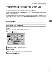
...} key. 37 When you use . B) Change the default settings to those you press this key, the settings will be recalled instantly. Whenever you often use . Programming Settings You Often Use Programming Settings You Often Use There are two ways of job setting. C Make a copy. B Input the settings you want to use . The machine memorizes the types of programming settings you turn on the machine or press the {Clear Modes/Energy Saver} key, these...
...} key. 37 When you use . B) Change the default settings to those you press this key, the settings will be recalled instantly. Whenever you often use . Programming Settings You Often Use Programming Settings You Often Use There are two ways of job setting. C Make a copy. B Input the settings you want to use . The machine memorizes the types of programming settings you turn on the machine or press the {Clear Modes/Energy Saver} key, these...
Operating Instructions
Page 55
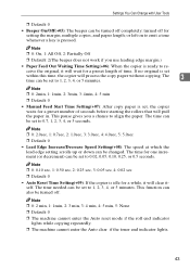
... be set to emit a tone whenever a key is set , the copier waits for a preset number of time. The time for setting the margin, multiple copies, and paper length; Note ❒ 0: 2 min, 1: 1min, 2: 3 min, 3: 4 min, 4: 5 min, 5: None ❒ Default: 0 ❒ The machine cannot enter the Auto reset mode if the roll end indicator lights while copying repeatedly. ❒ The machine cannot enter the Auto clear if the toner end indicator lights. 43...
... be set to emit a tone whenever a key is set , the copier waits for a preset number of time. The time for setting the margin, multiple copies, and paper length; Note ❒ 0: 2 min, 1: 1min, 2: 3 min, 3: 4 min, 4: 5 min, 5: None ❒ Default: 0 ❒ The machine cannot enter the Auto reset mode if the roll end indicator lights while copying repeatedly. ❒ The machine cannot enter the Auto clear if the toner end indicator lights. 43...
Operating Instructions
Page 64
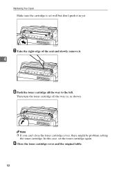
Note ❒ If you can't close the toner cartridge cover, there might be problem setting the toner cartridge. Then turn the toner cartridge all the way to the left. In this case, set well but don't push it . 4 H Push the toner cartridge all the way in yet. Maintaining Your Copier Make sure the cartridge is set the toner cartridge again. I Close the toner cartridge cover and the original table. 52 G Take the right edge of the seal and slowly remove it in , as shown.
Note ❒ If you can't close the toner cartridge cover, there might be problem setting the toner cartridge. Then turn the toner cartridge all the way to the left. In this case, set well but don't push it . 4 H Push the toner cartridge all the way in yet. Maintaining Your Copier Make sure the cartridge is set the toner cartridge again. I Close the toner cartridge cover and the original table. 52 G Take the right edge of the seal and slowly remove it in , as shown.
Operating Instructions
Page 96
... If You Cannot See the Roll Paper Jam, 68 L Loading A Roll Of Paper, 56 M Machine Environment, 75 Maintaining Your Copier, 47 Manual Feed Mode, 16 N Non-recommended Originals, 7 Notes for Leading and Side Edges of the Originals, 7 O Operation Panel, 3 Options, 83 Others, 71 P Partial Copying, 34 Power connection, 76 Preset Cutting, 24 Programming Setting You Often Use, 37 R Recommended Originals, 6 Recommended Paper, 8 Removing the Roll Paper Holder, 54 84
... If You Cannot See the Roll Paper Jam, 68 L Loading A Roll Of Paper, 56 M Machine Environment, 75 Maintaining Your Copier, 47 Manual Feed Mode, 16 N Non-recommended Originals, 7 Notes for Leading and Side Edges of the Originals, 7 O Operation Panel, 3 Options, 83 Others, 71 P Partial Copying, 34 Power connection, 76 Preset Cutting, 24 Programming Setting You Often Use, 37 R Recommended Originals, 6 Recommended Paper, 8 Removing the Roll Paper Holder, 54 84
Operating Instructions
Page 97
S Safety Information, i Setting a Leading Edge Margin/Trailing Edge Margin, 32 Settings You Can Change with User Tools, 42 Setting the Number of Copies (Repeated Copying), 31 Setting the Roll Paper Holder, 54 Something Happens, but Set Paper or Paper Select Never Appear, 71 Specifications, 79 Synchro Cutting, 21 T Toner, 10 Toner Storage, 10 Troubleshooting, 61 Turning on the Power, 5 Turn off the Main Power, 5 Turn on the Main Power, 5 U Used Toner, 10 User Tools, 40 Using the Rear Table, 19 V Variable Cutting, 25 W Where to Put Your Copier, 75 White Spots Appear, 71 85
S Safety Information, i Setting a Leading Edge Margin/Trailing Edge Margin, 32 Settings You Can Change with User Tools, 42 Setting the Number of Copies (Repeated Copying), 31 Setting the Roll Paper Holder, 54 Something Happens, but Set Paper or Paper Select Never Appear, 71 Specifications, 79 Synchro Cutting, 21 T Toner, 10 Toner Storage, 10 Troubleshooting, 61 Turning on the Power, 5 Turn off the Main Power, 5 Turn on the Main Power, 5 U Used Toner, 10 User Tools, 40 Using the Rear Table, 19 V Variable Cutting, 25 W Where to Put Your Copier, 75 White Spots Appear, 71 85
Service Manual
Page 89
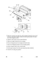
... [H] into each arm pin [C] into the roll paper. 6. SM 3-15 A163 Check the roll cutting rail operation. Set the paper between the cutter guide stay [J] and slide shafts [K]. 10. Attach the roll paper arms [A] to fix the roll paper position. 8. Install the cutter guide on the roll shaft holder. 9. [K] [A] [J] [G] [C] [E] [B] [H] [D] [C] [F] [G] [A] [H] [I] [I ] inside to the cutter guide [B]. (Install each cutter guide hole [D]. Fit the roll flanges [I] onto...
... [H] into each arm pin [C] into the roll paper. 6. SM 3-15 A163 Check the roll cutting rail operation. Set the paper between the cutter guide stay [J] and slide shafts [K]. 10. Attach the roll paper arms [A] to fix the roll paper position. 8. Install the cutter guide on the roll shaft holder. 9. [K] [A] [J] [G] [C] [E] [B] [H] [D] [C] [F] [G] [A] [H] [I] [I ] inside to the cutter guide [B]. (Install each cutter guide hole [D]. Fit the roll flanges [I] onto...

Service Manual
Page 98
... using alcohol. 1. Replace the hot roller. 9. Clean the feed roller using suitable solvent. Lubricate using G501 if necessary. 3. Lubricate using G501 if necessary. 2. Clean the fusing thermistors using water. 2. Others (every 3.6K) 10. Clean the registration roller using suitable solvent. 2. Fusing Unit (every 3.6K) Fusing Unit (every 6.4K) Fusing Unit (every 48K) 1. Inspect the drive gears. Replace the ozone filter. 1. Roll Feeder (every 3.6K) 11. Check the copy quality. 2. Perform the light sensor adjustment. Copy...
... using alcohol. 1. Replace the hot roller. 9. Clean the feed roller using suitable solvent. Lubricate using G501 if necessary. 3. Lubricate using G501 if necessary. 2. Clean the fusing thermistors using water. 2. Others (every 3.6K) 10. Clean the registration roller using suitable solvent. 2. Fusing Unit (every 3.6K) Fusing Unit (every 6.4K) Fusing Unit (every 48K) 1. Inspect the drive gears. Replace the ozone filter. 1. Roll Feeder (every 3.6K) 11. Check the copy quality. 2. Perform the light sensor adjustment. Copy...
Service Manual
Page 161
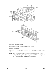
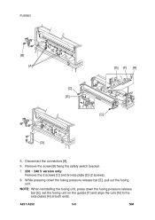
NOTE: While pressing down the fusing pressure release bar [D], pull out the fusing unit. Remove the 2 screws [C]. 8. While pressing down the fusing pressure release bar [D], set the fusing unit on the guides [E] and align the cuts [F] to the side plates [G] at both ends when reinstalling the fusing unit. Disconnect the connectors [A]. 6. SM 5-27 A163 Remove the screw [B] fixing the safety switch bracket. 7. [C] [D] [F] [E] [G] [C] [B] [A] 5.
NOTE: While pressing down the fusing pressure release bar [D], pull out the fusing unit. Remove the 2 screws [C]. 8. While pressing down the fusing pressure release bar [D], set the fusing unit on the guides [E] and align the cuts [F] to the side plates [G] at both ends when reinstalling the fusing unit. Disconnect the connectors [A]. 6. SM 5-27 A163 Remove the screw [B] fixing the safety switch bracket. 7. [C] [D] [F] [E] [G] [C] [B] [A] 5.
Service Manual
Page 258
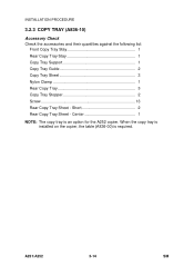
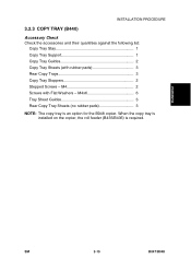
A251/A252 3-14 SM When the copy tray is installed on the copier, the table (A836-00) is an option for the A252 copier. Short 2 Rear Copy Tray Sheet - INSTALLATION PROCEDURE 3.2.3 COPY TRAY (A836-10) Accessory Check Check the accessories and their quantities against the following list: Front Copy Tray Stay 1 Rear Copy Tray Stay 1 Copy Tray Support 1 Copy Tray Guide 2 Copy Tray Sheet 3 Nylon Clamp 1 Rear Copy Tray 3 Copy Tray Stopper 2 Screw 13 Rear Copy Tray Sheet - Center 1 NOTE: The copy tray is required.
A251/A252 3-14 SM When the copy tray is installed on the copier, the table (A836-00) is an option for the A252 copier. Short 2 Rear Copy Tray Sheet - INSTALLATION PROCEDURE 3.2.3 COPY TRAY (A836-10) Accessory Check Check the accessories and their quantities against the following list: Front Copy Tray Stay 1 Rear Copy Tray Stay 1 Copy Tray Support 1 Copy Tray Guide 2 Copy Tray Sheet 3 Nylon Clamp 1 Rear Copy Tray 3 Copy Tray Stopper 2 Screw 13 Rear Copy Tray Sheet - Center 1 NOTE: The copy tray is required.
Service Manual
Page 271
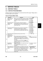
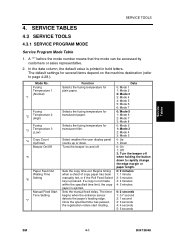
... Mode original exit roller stops before completely 1: Original Hold mode feeding out the original. SM 4-1 A251/A252 SERVICE TABLES 4.3 SERVICE TOOLS 4.3.1 SERVICE PROGRAM MODE All items except for 2: 3 seconds *14 the rear feed is actuated (A252 copier only). 3: 4 seconds 4: 5 seconds 5: 6 seconds 6: 7 seconds Auto Shut-off Time Determines the auto shut-off time. *15 Setting (120 V 1 ← 30 → 240 machines only) Original Hold After original scanning is...
... Mode original exit roller stops before completely 1: Original Hold mode feeding out the original. SM 4-1 A251/A252 SERVICE TABLES 4.3 SERVICE TOOLS 4.3.1 SERVICE PROGRAM MODE All items except for 2: 3 seconds *14 the rear feed is actuated (A252 copier only). 3: 4 seconds 4: 5 seconds 5: 6 seconds 6: 7 seconds Auto Shut-off Time Determines the auto shut-off time. *15 Setting (120 V 1 ← 30 → 240 machines only) Original Hold After original scanning is...
Service Manual
Page 296
NOTE: When reinstalling the fusing unit, press down the fusing pressure release bar [E], pull out the fusing unit. A251/A252 5-8 SM While pressing down the fusing pressure release bar [E], set the fusing unit on the guides [F] and align the cuts [G] to the side plates [H] at both ends. Remove the screw [B] fixing the safety switch bracket. 7. 220 ~ 240 V version only: Remove the 2 screws [C] and bronze plate [D] (2 screws). 8. FUSING [B] [A] A252R507.WMF [C] [E] [G] [F] [H] [C] A252R508.WMF [D] A252R506.WMF 5. Disconnect the connectors [A]. 6.
NOTE: When reinstalling the fusing unit, press down the fusing pressure release bar [E], pull out the fusing unit. A251/A252 5-8 SM While pressing down the fusing pressure release bar [E], set the fusing unit on the guides [F] and align the cuts [G] to the side plates [H] at both ends. Remove the screw [B] fixing the safety switch bracket. 7. 220 ~ 240 V version only: Remove the 2 screws [C] and bronze plate [D] (2 screws). 8. FUSING [B] [A] A252R507.WMF [C] [E] [G] [F] [H] [C] A252R508.WMF [D] A252R506.WMF 5. Disconnect the connectors [A]. 6.
Service Manual
Page 359
M4 2 Screws with rubber pads 3 Rear Copy Trays 3 Copy Tray Stoppers 2 Stepped Screws - Installation SM 3-15 B047/B048 INSTALLATION PROCEDURE 3.2.3 COPY TRAY (B440) Accessory Check Check the accessories and their quantities against the following list: Copy Tray Stay 1 Copy Tray Support 1 Copy Tray Guides 2 Copy Tray Sheets (with Flat Washers - M4x6 6 Tray Sheet Guides 3 Rear Copy Tray Sheets (no rubber pads 3 NOTE: The copy tray is required. When the copy tray is installed on the copier, the roll feeder (B435/B436) is an option for the B048 copier.
M4 2 Screws with rubber pads 3 Rear Copy Trays 3 Copy Tray Stoppers 2 Stepped Screws - Installation SM 3-15 B047/B048 INSTALLATION PROCEDURE 3.2.3 COPY TRAY (B440) Accessory Check Check the accessories and their quantities against the following list: Copy Tray Stay 1 Copy Tray Support 1 Copy Tray Guides 2 Copy Tray Sheets (with Flat Washers - M4x6 6 Tray Sheet Guides 3 Rear Copy Tray Sheets (no rubber pads 3 NOTE: The copy tray is required. When the copy tray is installed on the copier, the roll feeder (B435/B436) is an option for the B048 copier.
Service Manual
Page 371
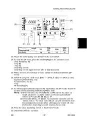
... call service indicators will blink (SP mode). 26. Enter "1" (B435: 1 roll) or "2" (B436: 2 rolls) by pressing the following keys on the operation panel: Clear Modes key [A] + key [B] - Press the Clear Modes key 3 times to switch between the two rolls. 28. Select 40 using the + and - SM 3-27 B047/B048 To set , the paper cut length adjustments, input values into SP modes 42 and 45 as listed on...
... call service indicators will blink (SP mode). 26. Enter "1" (B435: 1 roll) or "2" (B436: 2 rolls) by pressing the following keys on the operation panel: Clear Modes key [A] + key [B] - Press the Clear Modes key 3 times to switch between the two rolls. 28. Select 40 using the + and - SM 3-27 B047/B048 To set , the paper cut length adjustments, input values into SP modes 42 and 45 as listed on...
Service Manual
Page 375
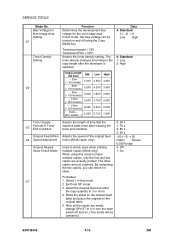
... off when holding the button down . Sets the manual feed delay. Data 0: Mode 1 1: Mode 2 2: Mode 3 3: Mode 4 4: Mode 5 5: Mode 6 6: Mode 7 0: Mode 5 1: Mode 6 2: Mode 7 3: Mode 8 0: Mode 2 1: Mode 3 2: Mode 4 3: Mode 5 0: Up 1: Down 0: On 1: Off 2: Turn the beeper off . The default settings for translucent film. Selects the fusing temperature for plain paper. Select weather the user display panel counts up or down to page 4-28.). Sets the copy time-out. Begins timing when a sheet of copy paper has been manually fed, or if the Roll Feed Select key is printed in bold letters...
... off when holding the button down . Sets the manual feed delay. Data 0: Mode 1 1: Mode 2 2: Mode 3 3: Mode 4 4: Mode 5 5: Mode 6 6: Mode 7 0: Mode 5 1: Mode 6 2: Mode 7 3: Mode 8 0: Mode 2 1: Mode 3 2: Mode 4 3: Mode 5 0: Up 1: Down 0: On 1: Off 2: Turn the beeper off . The default settings for translucent film. Selects the fusing temperature for plain paper. Select weather the user display panel counts up or down to page 4-28.). Sets the copy time-out. Begins timing when a sheet of copy paper has been manually fed, or if the Roll Feed Select key is printed in bold letters...
Service Manual
Page 390
... the 0: 60 s -23 Periods in this mode. 2. Procedure -27 1. Exit from SP mode. 3. The toner density changes according to 0 or turn the main switch off using the Copy Media key. In this mode to 3 or more. 4. The other copies are actually printed. SERVICE TOOLS Mode No. Select 1 in Toner End Condition machine adds toner after clearing the 1: 70 s toner end condition. 2: 80 s 3: 90 s Original Feed Motor Adjusts the speed of the original...
... the 0: 60 s -23 Periods in this mode. 2. Procedure -27 1. Exit from SP mode. 3. The toner density changes according to 0 or turn the main switch off using the Copy Media key. In this mode to 3 or more. 4. The other copies are actually printed. SERVICE TOOLS Mode No. Select 1 in Toner End Condition machine adds toner after clearing the 1: 70 s toner end condition. 2: 80 s 3: 90 s Original Feed Motor Adjusts the speed of the original...
Service Manual
Page 433
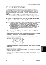
... the copier on the temperature mode. Then, calculate the average difference. 3. Make sure the average cut length is installed and/or paper type used. The cut error correction data is installed to 89. Preset Cut : Adjustment standards: ±3 mm (for Length Shorter than 420 mm) ±5 mm (for 420 to 47 when the 2 rolls feeder is installed. Make 5 copy samples of the length between...
... the copier on the temperature mode. Then, calculate the average difference. 3. Make sure the average cut length is installed and/or paper type used. The cut error correction data is installed to 89. Preset Cut : Adjustment standards: ±3 mm (for Length Shorter than 420 mm) ±5 mm (for 420 to 47 when the 2 rolls feeder is installed. Make 5 copy samples of the length between...
Service Manual
Page 440
... Function Auto off time can be selected Settings 1~ 120 minutes (1 minute per step) Default : 30 minutes The Auto Off time can also be selected by the customer. Continued... Replace page 4-11 of the Field Service Manual with the updated page provided with an incorporated coil is shown below. Main Switch AC Harness Relay Upper DC Harness ELECTRICAL PAPER PATH F S M PARTS Lower DC Harness • SP MODE New software...
... Function Auto off time can be selected Settings 1~ 120 minutes (1 minute per step) Default : 30 minutes The Auto Off time can also be selected by the customer. Continued... Replace page 4-11 of the Field Service Manual with the updated page provided with an incorporated coil is shown below. Main Switch AC Harness Relay Upper DC Harness ELECTRICAL PAPER PATH F S M PARTS Lower DC Harness • SP MODE New software...
Service Manual
Page 471
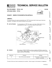
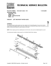
... GENERAL: Two additional paper guides (pawls) have been added to the Transfer/Separation Corona Unit to further ensure that the copy paper does not come into contact with the modified parts for all A163/A251/A252 Parts Catalogs. „ PARTS Copyright 2003 RICOH Corporation. N/A LANIER - Page 1 of 2 All rights reserved. TECHNICAL SERVICE BULLETIN BULLETIN NUMBER: A163/A251/A252 - 011 APPLICABLE MODEL: GESTETNER - This...
... GENERAL: Two additional paper guides (pawls) have been added to the Transfer/Separation Corona Unit to further ensure that the copy paper does not come into contact with the modified parts for all A163/A251/A252 Parts Catalogs. „ PARTS Copyright 2003 RICOH Corporation. N/A LANIER - Page 1 of 2 All rights reserved. TECHNICAL SERVICE BULLETIN BULLETIN NUMBER: A163/A251/A252 - 011 APPLICABLE MODEL: GESTETNER - This...
Service Manual
Page 479
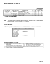
... units manufactured after the serial numbers listed below will have the new style parts installed during production. Toner Hopper Joint Shaft Unit - MODEL NAME RICOH FW770 Gestetner A040 SAVIN 7700W Lanier LW110 RICOH FW780 Gestetner A040 SAVIN 7800W Lanier LW111 SERIAL NUMBER H8630400001 H8730400001 INTERCHANGEABILITY CHART: 0 OLD and NEW parts can be used in . OLD parts can be used in OLD and NEW machines. 1 NEW parts can be used in or previously modified, use the new part numbers individually. Page...
... units manufactured after the serial numbers listed below will have the new style parts installed during production. Toner Hopper Joint Shaft Unit - MODEL NAME RICOH FW770 Gestetner A040 SAVIN 7700W Lanier LW110 RICOH FW780 Gestetner A040 SAVIN 7800W Lanier LW111 SERIAL NUMBER H8630400001 H8730400001 INTERCHANGEABILITY CHART: 0 OLD and NEW parts can be used in . OLD parts can be used in OLD and NEW machines. 1 NEW parts can be used in or previously modified, use the new part numbers individually. Page...


